Genelec 8000-325B/W Table stand L-shape Benutzerhandbuch
- Kategorie
- Flachbildschirm-Schreibtischhalterungen
- Typ
- Benutzerhandbuch

Sicherheitshinweise
- Nur für GENELEC Monitore 8x4x / 8x5x
- Festigkeit der Schraubverbindungen in
- regelmäßigen Abständen überprüfen.
- Nur auf geeigneten, d.h. ebenen und
- tragfähigen Untergründen verwenden.
- Die vier Gerätefüße mit Filzpads
- entkoppeln den Monitor und
- schützen den Untergrund vor Kratzern
Aufbau & Betrieb
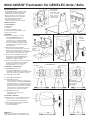
1. BESTANDTEILE
a. Adapterplatte
b. Standfuß
c. Justierschraube M8 x 33 mm
d. 4x Linsenkopfschrauben M6 x 12 mm
e. Inbusschlüssel SW4
2. MONTAGE
2.a Zunächst ist zu klären, in welcher
2.a Lage der GENELEC-Monitor am
2.a Tischstativ befestigt werden soll
2.a (siehe dazu Kap. 3. AUSRICHTUNG),
2.a denn danach richtet sich, welches der
2.a diversen Lochbilder der Adapterplatte a
2.a mit der Rückseite des Monitors genau
2.a verschraubt wird.
2.b Adapterplatte a entsprechend der
2.b gewünschten Lage des Monitors an dessen
2.b Rückseite verschrauben, mittels der 2 oder
2.b 4 Linsenkopfschrauben M6 x 12 mm d und des
2.b Inbusschlüssels e. Anzugmoment ~8Nm.
2.c Monitor nun am Standfuß b einhängen.
2.c Dazu müssen gleichzeitig BEIDE Haken
2.c des Adapters in die Lagerbolzen des
2.c Standfußes eingehängt werden.
2.d Justierschraube M8 x 33 mm c in die Gewinde-
2.d buchse an der Rückseite des Standfußes
2.d eindrehen. Sie dient der Justage des
2.d Abstrahlwinkels (-6,5° bis +17,5°).
3. MONITOR – AUSRICHTUNG
3.a WAAGERECHTE Position
3.a der Modelle GENELEC 8341 oder 8351
3.a - Standardposition für bestes Abstrahlverhalten
3.a - Höhe des akustischen Zentrums: 330 mm
3.a.1 Mittige Montage: LINKS
3.a.2 Mittige Montage: RECHTS
3.a.3 Betrifft Monitor 8341:
3.a.3 Zur manuellen Einstellung des Setups ist es
3.a.3 nötig den Monitor zunächst AUSSERMITTIG
3.a.3 zu befestigen. Nur so sind die DIP-Schalter
3.a.3 der Monitorrückwand vollständig zugänglich.
3.a.3 Bleibt diese Einstellung auf Dauer bestehen,
3.a.3 sollte der Monitor anschließend wieder in
3.a.3 zentrischer Position montiert werden
3.b SENKRECHTE Position
3.b - Standardposition für klassische
3.b - 2-Wege-Monitore
4. MONITOR – NEIGUNG
4.a Der Monitor kann von der Waagerechten aus
4.a stufenlos um 6,5° nach unten bis zu 17,5°
4.a nach oben gerichtet eingestellt werden.
4.b Die Justage des Monitor-Neigungswinkels
4.b erfolgt durch Verdrehen der
4.b Justierschraube M8 c.
8000-325B/W Tischstativ für GENELEC 8x4x / 8x5x
GENELEC Oy
Olvitie 5, Fin-74100 Iisalmi, www.genelec.com
23276-000-56/68 Rev.14 03-80-295-00 10/17
Zu benutzende
Lochbilder bei
- horizontaler Lage:
- 8x4x - 51 x 108
- 8x5x - 70 x 127
- vertikaler Lage:
- beide - 70 mm
2. MONTAGE
4. NEIGUNG
3. AUSRICHTUNG - Befestigungsbeispiel 8x4x: 51 x 108 mm
Befestigungs-
beispiel
8x5x:
70 x 127 mm
2.c Adapterplatte einhängen 2.d
Justier-
schraube
eindrehen
Befestigungsbeispiel 8341:
51 x 108 mm
Mittig
3.a WAAGERECHT
3.b SENKRECHT - 8x4x / 8x5x
3.a 2 RECHTS3.a 1 LINKS
Mittig
3.a.3
Aussermittige
Montage, für
frei zugängliche
DIP-Schalter

Safety instructions
- Only for GENELEC 8x4x / 8x5x
- Inspect bolted assemblies regularly
- For use only on even surfaces
- Four felt-foots under the pedestal
- are designed to decouples vibrations
- between the monitor and the base.
- Furthermore it saves the desk from
- scratches.
Instructions
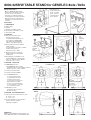
1. COMPONENTS
a. adaptor plate
b. pedestal
c. adjusting screw M8 x 33 mm
d. 4x pan head screws M6 x 12 mm
e. allen wrench SW4
2. MOUNTING
2.a First get a clear idea of the
2.a desired monitor position
2.a Tischstativ befestigt werden soll
2.a (see chapter 3. DIRECTION).
2.a This defines the needed hole
2.a pattern of the adaptor plate a.
2.b Bolt together the monitor with the
2.b adaptor plate a.
2.b Use pan-head-screws M6 x 12 mm d
2.b and the allen wrench e.
2.b Tightening torque: ~8Nm.
2.c Mount monitor by hooking the
2.c adaptor plate into both pedestal
2.c bearing bolts.
2.d Bolt adjusting screw M8x33 c into
2.d the threaded bush of the pedestal.
2.d This is for adjusting of the radiation
2.d angle (-6,5° up to + 17,5°).
3. MONITOR – DIRECTION
3.a HORIZONTAL position
3.a of the GENELEC 8341 or 8351
3.a - standard position for best radiation behavior
3.a - height of acoustic center: 330 mm
3.a.1 Centre mounting: LEFT
3.a.2 Centre mounting: RIGHT
3.a.3 For GENELEC 8341:
3.a.3 To create an appropriate
3.a.3 sound-setup an off-center
3.a.3 mounting of the monitor
3.a.3 is necessary. This keeps the
3.a.3 DIP-switches accessible.
3.a.3 In case of a long-term setup
3.a.3 we recommend to come back
3.a.3 to a centered mounting
3.b VERTICAL position
3.b - standard position for classic
3.b - two-way-monitors
4. MONITOR - INCLINATION ANGLE
4.a The monitor can be tilted step less from:
4.a 0°- down to -6.5°
4.a 0° - up to +17,5°
4.b For the adjustment of the inclination
4.b angle you have to turn the
4.b adjusting screw M8 c.
8000-325B/W TABLE STAND for GENELEC 8x4x / 8x5x
GENELEC Oy
Olvitie 5, Fin-74100 Iisalmi, www.genelec.com
23276-000-56/68 Rev.14 03-80-295-00 10/17
Hole patterns for:
- horizontal position:
- 8x4x - 51 x 108
- 8x5x - 70 x 127
- vertical position:
- both - 70 mm
2. MOUNTING
4. INCLINATION
4. ANGLE
3. DIRECTION - Mounting example 8x4x: 51 x 108 mm
Mounting
example
8x5x:
70 x 127 mm
2.c Hook in the adaptor plate 2.d
Insert
adjusting
screw
Mounting example 8341:
51 x 108 mm
centered
3.a HORIZONTAL
3.b VERTICAL - 8x4x / 8x5x
3.a 2 RIGHT3.a 1 LEFT
centered
3.a.3
Off-center
mounting for
accessible
DIP-switches
-
 1
1
-
 2
2


Genelec 8000-325B/W Table stand L-shape Benutzerhandbuch
- Kategorie
- Flachbildschirm-Schreibtischhalterungen
- Typ
- Benutzerhandbuch
Verwandte Artikel
-
Genelec 8000-420B/W Short wall mount Bedienungsanleitung
-
-
-
-
-
-
-
-
-
Genelec 8030 Bedienungsanleitung