Thorn Chalice 3 / CHAL3 200 1400-830 HFIX E3D RSB Installationsanleitung
- Typ
- Installationsanleitung

Mat.-Nr: 06 980 432/4/0 .231 10
1/11
UK ONLY
*only HFIX
See mounting
instructions!
Montážní návod
CS
Istuzioni di montaggio
IT
Szerelési útmutató
HU
Notice de montage
FR
Asennusohje
FI
Paigaldusjuhend
ET
Monteringsvejledning
DK
Montageanleitung
DE
Montavimo Instrukcijos
LT
Installation instructions
EN
Installationsanvisning
SV
RU инструкция по монтажу
Instrukcja montazu
PL
Monteringsanvisning
NO
Instalacijas instrukcija
LV
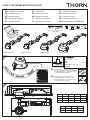
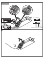
CHAL EHF HFIX3 100/150/200 / E3/ E3D
CHAL3 100 H CHAL3 100 L
EN
The servici g of the control gear in thisn
luminaire ould only be undertaken bysh
th anufacturer or his service agente m
or a similar qualified person.
EN
Th light source contained in thise
luminaire shall only be replaced by
the m nufacturerorhisserviceagenta
or milar qualified person.a si
Replaceability instruction
IP54
IP20
Made in Germany
220-240V ...Hz ...W
CHAL3...
Mod .......
Ser ....... ...mA
CHAL3 150 CHAL3 200
W
82
302
501
159
64 ≥50
≥50
1 - 40
4H
99
≥100*
*
3000lm ≥ 150
øDA
øD
L
≥50
W
(mm)
L
500
100H/L
600
500
150
650
500
200
700
ØDA
(mm)
ØD
100
100H
119
100
100L
119
150
150
174
200
200
223
H95 75 94 96

Mat.-Nr: 06 980 432/4/0 .231 10
2/11
RU Светильник не должен быть
закрыт теплоизолядией.
SV Armaturen får inte täckas
med värmeisolering.
Oprawa nie mo e by os oni tażćłę
materiałem izolacyjnym.
PL
FI Valaisinta ei saa peittää lämpöeristeillä.
HU A világitótestet h szigeteléssel ellátni tilos!ő
ET Valgusti ei tohi olla kaetud
soojusisolatsioonimaterjaliga.
CS Sv tla nesmí být zakryta materiálemě
tepelné izolace.
DE Leuchte darf nicht mit Wärmedämmung
abgedeckt werden.
EN Luminaire not suitable for covering
with thermally insulating material. FR Le luminaier na doit pas être recouvert
d´une isolation thermique.
DK Lampen må ikke tildækkes
med varmeisolerende materiale.
IT L´apparecchio non va assolutamente
coperto da isolamente termici.
Šviestuvo negalima padengti
termoizoliacine medžiaga.
LT
Lampa nav piem rota aplk šanaiēā
ar termoizolēju materiālu.
LV
NO Belysningsarmaturen må ikke tildekkes
med varmeisolerende materiale.
A lámpa kizárólag világításra szolgál és a
felszerelésre vonatkozó országos
rendelkezéseknek megfeleloen kell
felszerelni. Ettol eltéro használat vagy
beépítés “nem rendeltetésszerunek”
számít.
HU
Valaisin on tarkoitettu ainoastaan
valaistuskäyttöön, ja se on asennettava
kansallisten määräysten mukaan. Muu
käyttö tai muu asennus katsotaan
sopimuksenvastaiseksi käytöksi.
FI NO
Lampan är uteslutande avsedd för belys-
ning och skall installeras i enlighet med de
nationella installationsbestämmelserna. All
annan användning eller montering gäller
som “ej ändamålsenlig".
SV
RU Светильник предназначен только для
освещения и должен устанавливаться
в соответствии с национальными
монтажными нормами.
Lampen er udelukkende beregnet til
belysning, og skal installeres iht. de
nationale installationsbestemmelser. En
anden brug eller en anden montering
gælder som “ikke formålsbestemt.
DK
La lampada serve esclusivamente per
l'illuminazione e deve essere installata in
conformità con le norme nazionali per il
montaggio. Un altro uso o un diverso tipo
di incasso non è considerato conforme alle
disposizioni.
IT
Valgustit tohib kasutada üksnes
valgustamiseks ja see tuleb paigaldada
vastavalt riiklikele paigalduseeskirjadele.
Muul otstarbel kasutamine või
paigaldamine loetakse „eeskirjadele
mittevastavaks“.
ET
Osvetlovací teleso slouží výlucne k
osvetlení a je nutno je nainstalovat v
souladu s národními normami týkajícími se
pokládá za použití nebo montáž v rozporu
s urceným úcelem.
CS
Lampu paredzets izmantot tikai
apgaismošanas nolukos, un ta jauzstada
atbilstoši valsts noteikumiem par iericu
uzstadišanu.Jebkada citadaka lietošana
vai uzstadišana tiek uzskatita par
“neatbilstošu instrukcijai”.
LV
LT
Lampa sluzy wylacznie do oswietlenia i
nalezy ja zamontowac zgodnie z
krajowymi przepisami wykonawczymi.
Inne wykorzystanie lub inny montaz sa
uznawane za „niezgodne z
przeznaczeniem”.
PL
La lampe sert uniquement à l'éclairage et
doit être installée conformément aux pres-
criptions nationales en matière d'instal-
lation.Toute autre utilisation ou installation
est considérée comme "non conforme".
FR
The lamp is used exclusively for lighting
and is to be installed in accordance with
the national installation regulations. Any
other use or installation is regarded as
"not according to instructions".
EN
Die Leuchte dient ausschließlich der
Beleuchtung und ist entsprechend den
nationalen Errichtungsbestimmungen zu
installieren. Eine andere Nutzung oder ein
anderer Einbau gilt als „nicht
bestimmungsgemäß”.
DE
Lysene skal kun brukes til belysning, og
må installeres i overensstemmelse med de
nasjonale forskrifter. Annen bruk eller
annen montasje blir betraktet som “ikke
tiltenkt”.
Šviestuvas skirtas tik apšvietimui ir turi b tiū
irengiamas laikantis nacionaliniu irengimo
nuostatu. Kitoks naudojimas ar irengimas
laikomas „ne pagal paskirti“.
NO Montasje og igangkjøring må kun utføres
av autorisert fagpersonell.
RU Монтаж и ввод в эксплуатацию, должны
выполняться только авторизованными
специалистами.
SV Monteringen och idrifttagandet får endast
företas av auktoriserad fackpersonal.
FI Asennuksen ja käyttöönoton saa tehdä
vain auktorisoitu ammattihenkilöstö.
HU Csak szakképzett személyzet végezeti a
szerelést és az üzembe helyezést.
Montaz i uruchomienie moga byc
przeprowadzane wylacznie przez
autoryzowany personel.
Montuoti ir paruošti eksploatacijai gali tik
autorizuoti specialistai.
Veikt uzstadišanu un nodot ierici
ekspluatacija drikst tikai autorizeti
specialisti.
ET Montaaži ja kasutuselvõttu tohivad teha
üksnes selleks volitatud spetsialistid.
CS Montáž a uvedení do provozu smí
provádet pouze oprávnený odborný
personál.
DE Die Montage und Inbetriebnahme darf nur
von autorisiertem Fachpersonal durch-
geführt werden.
EN Installation and commissioning ma y only
be carried out by authorized specialists. FR L'installation et la mise en service doivent
obligatoirement être effectuées par des
techniciens.
DK Montering og ibrugtagning må kun
foretages af autoriseret fagpersonale.
IT Montaggio ed avviamento devono essere
eseguiti solo da personale specializzato.
LT
LV
PL

Mat.-Nr: 06 980 432/4/0 .231 10
3/11
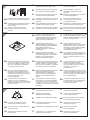
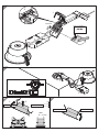
4EHF E3
DA DA LN
EHF E3
in use
not in use
not in use
L
N
L'
x
1.
2.
Max. 3 x 1,5 mm²
30 9
max.
8,5 mm
3
1 2
DA
200
100100 H/L
CHAL3
150150
200
3.
4.
5.
1.
2.
Option/
Accessory 96239327
1.
2.
3.

LNDADA
in use
DA DA
L
N
x
HFIX E3
in use
x
1.
2.
Max. 2 x 1,5 mm²
30 9
Max. 3 x 1,5 mm²
30 9
Max.
8,5 mm
Max.
8,5 mm
5HFIX E3
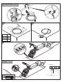
6EHF E3D
7HFIX E3D
Only UK
Mat.-Nr: 06 980 432/4/0 .231 10
4/11
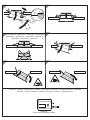
1.
LN
EHF E3D
DA DA
Em ncyerge
DA IL
in use
DA DA
L
N
L'
x
2.
Max. 2 x 1,5 mm²
Max.
8,5 mm
30 9
Max. 3 x 1,5 mm²
Max.
8,5 mm
30 9
1.
2.
3.
UK Only
Max. 2 x 1,5 mm²
Max.
8,5 mm
30 9
Max. 2 x 1,5 mm²
Max.
8,5 mm
30 9
LNDADA
in use
DA DA
L
N
x
HFIX E3D
DA DA
Em ncyerge
DA IL
xxx x
x
in use
UK o lyn

5/11 Mat.-Nr: 06 980 432/4/0 .231 10
9
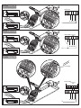
8HFIX E3D
1.
2.
3.
Max. 4 x 1,5 mm²
Max.
8,5 mm
30 9
Max. 2 x 1,5 mm²
Max.
8,5 mm
110 9
LN
HFIX E3D
DA DA
DA DA
Em ncyerge
DA IL
in use
DA DA
L
N
Em ncyerge
DA IL
DA DA
xxx x
xx
in use
CLACK!

6/11 Mat.-Nr: 06 980 432/4/0 .231 10
11
12 13
1. 2.
H
100H
H > 10 mm
10
2.
1.
3.
CLACK!
Date of Installation
1.
2.

Mat.-Nr: 06 980 432/4/0 .231 10
7/11
3 4
1.
2.
1Dismantling - Demontage - Demontáž - afmontering
demonteerimine - Purkaminen - Démontage - szétszerelés
Smontaggio - išmontavimas - demont ža - Demonteringā
Demonta - Demontering -ż Демонтаж
14 15
1.
2.
3.
2
CHAL3 AKKU EM BOX E3D/E3
59013417
Accessory - Zubehör - Príslusenství - Tilbehør - Lisatarvikud - Lisätarvike - Accessoire éventuel - tartozékok
Accessori - Priedai - Piederumi - Tillbehör - Akcesoria - Tillbehör - Принадлежности

Mat.-Nr: 06 980 432/4/0 .231 10
8/11
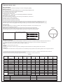
Position offitting
Installation date
Tel. no.
InstallerDescription offitting
To be completed on installation
Maintenance and testing
Emergency lighting systems must be tested regularly to ensure that they function, and that the useful life of batteries remains within the
specification.The system can be tested by disconnecting the supply to the emergency current circuit and, if required, also to
the normal on/offfunction.Test results should be recorded in theTest Log.
Daily
Check if the charge indicator (green ).LED
Monthly
To ensure that the system is functioning correctly, thefitting should be switched over to battery operation for a short time.
Every year
The fitting must be switched over to battery operation for 3 hours.Battery change required if the 3h battery operation can no longer be achieved.
The above tests should be performed at times when any external disturbances are minimal. It is important that the system has received an
uninterrupted current supply for at least 24 hours before testing.
Switches connected to the emergency lighting system should not be accessible to unauthorised persons.
Battery instructions
Type: High-temperature LiFe 4 batterypack for use with emergency lighting unitsPO
•3-year guarantee from delivery date
•Optimal storage conditions are:
•4-6 year design life (up to 45°C ambient temperature)
Temperature: -20 ... +25°C up to 12 months after printed date of manufacture
Emergency units with or without monitoring for 3 hours of emergency lighting.
EN
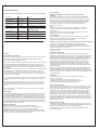
Test Log
Label
Figure 1
LED function :(only valid for E3)
Note Statusindication (only valid for E3)LED
The status indication switches off if the battery does not reach the full capacity (3,6V battery voltage) within 20-30 hours.LED
If this occurs disconnect the main voltage and operate the device in the emergency mode for approximately one hour.
Afterwards apply the mains voltage again and recharge the battery for 24 hours. If the failure occurs again replace the battery
LED does not light up: no charging of battery
The serves solely for charging control according to 60598-2-22, clause 22.7.7.LED IEC
LED lights up green: battery is charging
Commissioning
Fill in date and signature on the label of the battery. After checking the installation, connect the battery to the
emergency gear then switch on the mains.
Please stick the included label (Figure 1) on the luminaire and enter the electric circuit designation.
Initial charging time: 20 hours. Each following charging: 10 to 15 hours.Temperature range: 0°C to 50°C.
Emergency lighting level:The emergency lighting level is dependent on the type of lamp and wattage.
LUMINAIRE VERSION E3/E3D
Device designation
5th year
Signature Date
4th year
Signature Date
3rd year
Signature Date
2nd year
Signature Date
1st year
Signature Date
Test
Functions
Functions
Functions
Functions
Functions
Functions
Functions
Functions
Functions
Functions
Functions
3h use
Lenght of use
Month
1
2
3
4
5
6
7
8
9
10
11
12
Date Comments Date Comments

Mat.-Nr: 06 980 432/4/0 .231 10
9/11
Testing
DALI Control (only E3D)
ADALI command from a suitable control unit can be used to initiate function
and duration tests at individually selected times. Statusflags are set for
report back and data logging of results.
When a bus has not been connected or when a bus is connectedDALI DALI
but the default and times have not been re-setDALI DELAY INTERVAL
by sending appropriate commands, then the converterDALI EM LED PRO
will conduct self-tests in accordance with the default times set within the
EEPROM.
These default times are factory pre-set, in accordance with the stanDALI dard
EN 62386-202, to conduct an automatic function test every 7 days and
a duration test every 52 weeks. Since the time is factory pre-set toDELAY
Zero, all units are tested at the same time.Test times can be changed with a
command over the bus.DALI
The and time values must be re-set when the emergencyDELAY INTERVAL
system test times are to be scheduled by a control and monitoringDALI
system.
Note that once the default values have been set to Zero, tests will only be
conducted following a command from the control system. If the bus isDALI
disconnected the converter does not revert to self-testingEM LED PRO
mode.
Note: If the battery is connected the communication is only possibleDALI
after power reset.
Addressing
The converter includes the easy addressing system whichEM LED PRO EZ
allows addressing and identification by using the bi-colour in conjuncLED
tion with the addressing tool. Binary address codes given by theEM PRO
LED DALIcan be simply converted to the addresses 0 to 63. For single han
ded addressing using this method it is necessary to send a broadcast ident
command every 3 to 9 seconds. During this command the s will be switLED
ched offand the indication willflash the 6 bit binary address precededLED
( =maintained mode). Luminaire where the lamp for emergency lightingMM
Emergency luminaire in maintained mode ( ) or switchedMM
by a 3 second start indication period.
Commissioning
After installation of the luminaire and initial connection of the mains and-
battery supply to the converter the device startswithEM LED PRO
a 24 hours initial charge for LiFe 4 batteries.PO
Afterwards the device conducts a commissioning test for the full duration.
The 24 hours recharge forLiFe 4 batteries occurs also with thePO
connection of a new battery.The following automatic commissioning
duration test only takes place when abattery is replaced and fully charged
and the interval time is not set to zero.
In case the interval time is set to zero the device expects the system toDALI
request the testing.
Rest Mode / Inhibit Mode
Emergency operation is automatically started when the mains supply is
switched off. If the Rest Mode is activated, the discharging of the battery will
be minimized by switching offthe output. If the Inhibit Mode has beenLED
activated before the mains supply is switched off, Rest Mode will be automa-
tically switched on if the mains supply is switched off within 15 minutes.
Rest Mode and Inhibit Mode can be initiated by the controller. TheDALI
RESTcommand has to be sent after the mains supply has been discon-
nected and while the converter is in emergency operation.EM LED PRO
The command has to be sent while the converter isINHIBIT EM LED PRO
supplied by mains.
After a mains reset the converter exits the Rest Mode. RestEM LED PRO
Mode and Inhibit Mode can both be disabled by sending the - /RE LIGHT
RESETINHIBITcommand. Rest Mode / Inhibit Mode are not supported from
EM LED POconverter in case of combination with a 1-cell LiFe 4 battery and
2-cell Ni battery.MH
Test switch
An optional test switch can be wired to each converter .EM LED
This can be used to to:
• Execute function test as long as switch pressed: press >1 s
• Initiate a 5 seconds function test: press 200ms < T < 1s
• Reset selftest timer (adjust local timing): press >10 s
Timer reset functionality
The timer for function and duration test can be set to a particular time of the
day by either pressing the test switch for longer than 10 seconds or cycling
the unswitched line supply 5 times within 1 minute.The timer adjustment
will enable the test start time to be defined manually at time in day when
the timer was reset. It will also disable the adaptive test algorithm thereby
forcing the unit to perform the test at the same time rather than it being
defined by the adaptive algorithm.This function will only work provided the
interval time is greater than zero (automatic test mode enabled).The factory
programmed delay offset (1–28 days) will be loaded after the reset into the
delay timer for the function and duration test in order to randomize the tests
between adjacent units.
BlackBox data recording
Parameters providing information about the application and use are stored
in the converter .The parameters stored provide information onEM LED PRO
the mains, battery, output and emergency operation.LED
The BlackBox can be read out with the master andCONFIGURATOR
device .- ANALYSER
Notes on installation
maintained mode: Luminaire where the lamp for emergency lighting is
operated continuously both in normal and in emergency mode
is switched together with the general lighting. In emergency mode the lamp
is always in operation! (Switched maintained mode).
Commissioning -
after the building phase, if the mains voltage is continually
available !
Write the date and sign in the space on the battery marked“Installation”.
After checking that the wiring has been performed correctly, connect the
emergency unit to the battery.Then switch on the power supply from the
mains. Please stick the red self-adhesive label stating onto the luminaire.
the emergency luminaire to be given a red mark and the electric
The electric circuits can then be marked. 50172 and requireEN ICEL
circuits to be marked.
EN
Note:
An ongoing review of the safety luminaire is required by the building
operator. Aconsultation of the system documentation of 3 years is
Potential breakdowns in the electronic system, batteries os s areLED
required here.
possible here. Any variances must be logged.
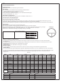
Status indication E3D
System status is indicated by a bi-colour and by a statusflag.LED DALI
Status CommentLED indication
System OK AC modePermanent green
Function testFast flashing green
underway(0,1 sec on - 0,1 sec off)
Duration test
Load failure open circuit / Short circuit / failureLEDRed onLED
Battery failure Battery failed the duration test or functionSlow flashing red
test / Battery is defect or deep discharged /
Incorrect battery voltage
Slow flashing green
underway(1 sec on - 1 sec off)
(1 sec on - 1 sec off)
Charging failure Incorrect charging currentFast flashing red
Inhibit mode Switching into inhibit mode via controllerDouble pulsing green
DC mode Battery operation (emergency mode)Green and red off
(0,1 sec on - 0,1 sec off)
Address
identification
During address identification modeBinary transmission of
address via green/red LED

Mat.-Nr: 06 980 432/4/0 .231 10
10/11
Position/Ort der Leuchte
Installationsdatum
Telefonnr
InstallateurLeuchtenbeschreibung
Bei der Installation ausfüllen
Wartung und Prüfung der Notbeleuchtung
Um die Funktion der Notbeleuchtung sicherzustellen ist die Anlage in Perioden durch Tests zu überprüfen, und ob die Laufzeit des Akkus
wie angegeben ist.
Die Anlage kann getestet werden indem die Netzspannung zum Notstromkreis unterbrochen wird, oder wenn es notwendig ist zu der normalen
Stromversorgung. Das Testresultat sollte im Testprotokoll notiert werden.
Tägliche Prüfung
Kontrollieren Sie, dass der Ladeindikator leuchtet (grüne Leuchtdiode).
Monatliche Prüfung
Um zu kontrollieren, dass die Anlage korrekt funktioniert, sollte die Leuchte kurzweilig auf den Akkubetrieb umgeschaltet werden.
Jährliche Prüfung
Die Leuchte wird 3 Stunden lang auf Akkubetrieb umgeschaltet. Batteriewechsel erforderlich, wenn die 3h Akkubetrieb nicht mehr erreicht werden.
Die oben genannten Tests sollten an Zeitpunkten stattfinden wo es wenig stört. Es ist wichtig, dass die Anlage vor dem Test mindestens 24 Stunden
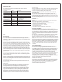
Test Log
Test
Funktion
Funktion
Funktion
Funktion
Funktion
Funktion
Funktion
Funktion
Funktion
Funktion
Funktion
3h Betrieb
Volle Betriebszeit
Month
1
2
3
4
5
6
7
8
9
10
11
12
1. Jahr
Unterschrift Datum
2. Jahr
Unterschrift Datum
3. Jahr
Unterschrift Datum
4. Jahr
Unterschrift Datum
5. Jahr
Unterschrift Datum
Datum Bemerkung Datum Bemerkung
ununterbrochen Stromzufuhr gehabt hat. Schalter mit Verbindung zu der Notbeleuchtungsanlage sollten nicht für unautorisierte Personen
zugänglich sein.
LEUCHTENVARIANTE E3/E3D
Notlichtleuchte mit und ohne Überwachung für 3h Notbetrieb
Gerätebezeichnung
Akku Hinweise
Typ: Hochtemperatur LiFe 4Akku Pack für die Nutzung mit NotlichtleuchtenPO
• 4-Jahre Lebensdauer (bis zu 45 °C Umgebungstemperatur)
• 3-Jahre Garantie nach Auslieferungsdatum
• Akku nicht länger als 12 Monate ohne Ladung nach Herstellerdatum aufAkku lagern.
Optimale Lagertemperatur -20 ... +25 °C.
DE
LED Funktion (nur gültig für E3):
LED leuchtet grün: Ladung des Akkus erfolgt
LED leuchtet nicht: keine Ladung des Akkus
Die dient ausschließlich der Ladekontrolle nach 60598-2-22 Abschnitt 22.7.7.LED IEC
Hinweis Statusanzeige- (nur gültig für E3)LED
Die Statusanzeige- schaltet sich aus, wenn der Akku nicht innerhalb von 20-30 Stunden die volle Kapazität (3,6V Akkuspannung) erreicht.LED
Trennen Sie in diesem Fall die Netzspannung und betreiben Sie das Gerät für ca. eine Stunde im Notbetrieb.
Legen Sie danach die Netzspannung wieder an und laden Sie den Akku für 24 Stunden auf. Tritt der Fehler erneut auf, tauschen Sie den Akku aus.
Inbetriebnahme
Datum und Unterschrift auf dem Akku. Beschriftungsfeld ausfüllen.
Nach Prüfung der Installation Versorgungsgerät mit der Batterie verbinden, dann Netz einschalten.
Beiliegendes selbstklebendes rundes Label (Abbildung 1) an die Leuchte kleben und die Stromkreiskennzeichnung eintragen.
Ladezeit bei der ersten Aufladung 20h. Jede weitere Aufladung 10 - 15 h. Temperaturbereich: 0°C bis 50°C.
Notlichtlevel: Der Notlichtlevel ist abhängig vom jeweiligen -Typ und Wattage.LED
Label
Abbildung 1

Mat.-Nr: 06 980 432/4/0 .231 10
11/11 www.thornlighting.com
Statusanzeige E3D
Der Systemstatus wird über eine zweifarbige und durch einLED DALI
Status Flag angezeigt.
Tests
DALI-Steuerung
Ein -Befehl von einem geeigneten Steuergerät kann dazu verwendetDALI
werden, die Funktions- und Betriebsdauertests zu individuell gewählten Zeiten
auszulösen. Für Rückmeldungen und Datenerfassung von Ergebnissen werden
Status-Flags gesetzt.
Wenn kein -Bus angeschlossen ist oder wenn zwar ein Bus ange-DALI DALI
schlossen ist, aber die voreingestellten Parameter „ “ und „ -DALI DELAY INTER
VAL DALI“ -Zeit nicht durch entsprechende Befehle zurückgesetzt wurden, dann
arbeitet das converter im Selbsttest-Betrieb und führt Tests in Über-EM LED
einstimmung mit den im voreingestellten Zeiten durch. Diese beidenEEPROM
Parameter sind ab Werk vorprogrammiert in Übereinstimmung mit dem DALI
Standard 62386-202. Ein Funktionstest wird dementsprechend alle 7TageEN
und ein Betriebsdauertest alle 52 Wochen durchgeführt. Da die eit abDELAYZ
Werk auf Null vorprogrammiert ist, werden alle Geräte zur gleichen Zeit getestet.
DieTestzeiten können durch einen entsprechenden Befehl über den -BusDALI
geändert werden.
Die und eiten müssen zurück- (auf Null) gesetzt werden,DELAY INTERVALZ
wenn die Notlicht-Testzeiten über ein Steuer- und ÜberwachungssystemDALI
bestimmt werden sollen.
Beachten Sie, dass sobald die voreingestellten Parameter auf Null gesetzt sind,
Tests nur nach Aufforderung durch das Steuersystem ausgeführt werden.DALI
Wenn der Bus abgeklemmt wird, kehrt das converter nicht in denDALI EM LED
Selbsttestbetrieb zurück.
Hinweis: Die -Kommunikation bei angeschlossenem Akku ist erst nachDALI
Netzreset möglich.
Adressierung
Das converter beinhaltet das easy addressing Adressiersystem,EM LED EZ
welches die Addressierung und Identifikation unter Verwendung der
zweifarbigen Status- in Verbindung mit dem addressing toolLED EM PRO
erlaubt. Binäre Adress-Codes die durch die angezeigt werden, könnenLED
einfach in die dressen 0 bis 63 konvertiert werden. Für die Addressie-DALI A
rung, welche diese Methode nutzt, ist es notwendig einen Broadcast Ident
Befehl alle 3 bis 9 Sekunden zu senden. Während der Ausführung dieses
Binäraddresse gefolgt von einer 3 Sekunden dauernden Startanzeigepause.
Befehls werden die s ausgeschaltet und die Status- blinkt die 6 BitLED LED
Inbetriebnahme
Nach der Installation der Leuchte und dem erstmaligen Anschluss der Netz-
und Akkuversorgung an das converter startet das GerätEM LED PRO
mit einer 24- stündigen Erstladung bei LiFe 4-Akkus.PO
Anschließend führt das Gerät einen Inbetriebnahmetest über die volle
Betriebsdauer durch.
Die 24 Stunden Erhaltungsladung für LiFe 4-Akkus erfolgen auchPO
beim Anschluss eines neuen Akkus. Der folgende automatische Inbetrieb-
nahme-Dauertest erfolgt nur bei Ersatz des Akkus und voller Ladung sowie
einer Intervallzeit ungleich Null.
Bei einer Intervallzeit gleich Null erwartet das Gerät, dass das -SystemDALI
denTest anfordert.
Prüftaster
Wahlweise kann ein Prüftaster an das converter angeschlossenEM LED
werden.
Dieser kann folgendermaßen verwendet werden:
• Für einen 5 Sekunden Funktionstest: drücke 200 ms <T< 1 s
• Ausführen eines Funktionstests solange
derTaster gedrückt ist: drücke > 1 Sekunde
• Reset des Selftest Timers
(Einstellen der lokalenTestzeit:drücke > 10 Sekunden
Rest Mode / Inhibit Mode
Bei einem Netzausfall wird der Notbetrieb automatisch gestartet. Bei
anschließender Aktivierung des „Rest Mode“ wird die Entladung der Batterie
durch das Abschalten des -Ausgangs minimiert. Bei einer AktivierungLED
des „Inhibit Mode“, innerhalb von 15 Minuten vor dem Deaktivieren der Netz-
spannung, schaltet das Gerät beim Ausfall der Netzspannung direkt in den
„Rest Mode“.
Die Aktivierung von„Rest Mode“und „Inhibit Mode“kann über erfolgen.DALI
Der - Befehl muss nach der Deaktivierung der Netzspannung,REST
während sich das converter im Notbetrieb befindet, gesendetEM LED PRO
werden. Der -Befehl muss während aktiver Netzspannung gesendetINHIBIT
werden.
Nach einem Reaktivieren der Netzspannung beendet das converterEM LED
PRO den „Rest Mode“. Die Deaktivierung von „Rest Mode“und „Inhibit Mode“
kann durch das Senden des Befehls - / erfolgen.RE LIGHT RESETINHIBIT
Rest Mode / Inhibit Mode werden vom converter bei KombinationEM LED
mit einem 1-Zellen-LiFe 4-Akku und einem 2-Zellen-Ni -Akku nichtPO MH
unterstützt.
Timer- Rückstellfunktion
Der Timer für den Funktions- und Betriebsdauertest kann zu einer
bestimmten Zeit desTages eingestellt werden, entweder durch Drücken
des Prüftaster länger als 10 Sekunden oder durch fünfmaliges Schalten der
ungeschaltenen Phase innerhalb von einer Minute. Durch Ausführen der
Timer- Rückstellfunktion werden alle vorher eingestellten Testzeiten durch
den Zeitpunkt der Rückstellung ersetzt und der adaptive Lernmodus zur
Ermittlung desTestzeitpunktes mit minimalem Risiko wird deaktiviert.
Diese Funktion wird nur dann unterstützt, wenn die Intervallzeit größer Null
ist (automatischer Testmodus aktiviert). Der werksseitig programmierte
Verzögerungs- Offset (1–28Tage) wird nach dem Zurücksetzen in den
Verzögerungstimer für den Funktions- und Dauertest geladen, um die Tests
zwischen benachbarten Geräten zufällig durchzuführen.
BlackBox Data Recording
Parameter, die Informationen über die Anwendung und Verwendung liefern,
sind im converter gespeichert. Die gespeicherten ParameterEM LED PRO
liefern Informationen über Netz, Batterie, -Ausgang und Notbetrieb.LED
Die BlackBox kann mit dem master und demCONFIGURATOR
device ausgelesen werden.ANALYSER
DE
Status KommentarLED Anzeige
System OK AC BetriebPermanent gün
FunktionstestSchnell blinkendes grün
läuft(0,1 sec ein - 0,1 sec aus)
Betriebsdauertest
Lastfehler Offener Schaltkreis / Kurzschluss / FehlerLEDRote einLED
Akkufehler Akku hat Betriebsdauer- oder FunktionstestLangsam blinkendes rot
nicht bestanden / Akku ist defekt /
Falsche Akkuspannung
Langsam blinkendes grün
läuft(1 sec ein - 1 sec aus)
(1 sec ein - 1 sec aus)
Ladefehler Falscher LadestromSchnell blinkendes rot
Block-Modus Umschalten in den Block-Modus
mittels Controller
Doppel blinkendes grün
DC Betrieb Akkubetrieb (Notbetrieb)Grün und rot aus
(0,1 sec ein - 0,1 sec aus)
Adress-
identifikation
Während AdressidentifikationsmodusBinäre Anzeige der Adresse
über grün/rote LED
-
 1
1
-
 2
2
-
 3
3
-
 4
4
-
 5
5
-
 6
6
-
 7
7
-
 8
8
-
 9
9
-
 10
10
-
 11
11


