Parkside PZKS 1500 A1 Operating And Safety Instructions Manual
- Typ
- Operating And Safety Instructions Manual

IAN 102960
SLIDING CROSS CUT MITRE SAW PZKS 1500 A1
ЦИРКУЛЯРЕН ТРИОН С ИЗТЕГЛЯНЕ И ГЕРУНГ
PZKS 1500 A1
Указания за обслужване и безопасност
Превод на оригиналното ръководство
BG
GRBG
ZUG- KAPP- UND GEHRUNGSSÄGE PZKS 1500 A1
Bedienungs- und Sicherheitshinweise
Originalbetriebsanleitung
DE AT CH
ΦΑΛΤΣΟΠΡΙΟΝΟ ΚΑΙ ΠΡΙΟΝΙ ΚΑΘΕΤΗΣ ΟΠΗΣ PZKS
1500 A1
Οδηγίες χειρισμού και ασφαλείας
Μετάφραση του πρωτοτύπου των οδηγιών χρήσης
GR
SLIDING CROSS CUT MITRE SAW PZKS 1500 A1
Operating and Safety Instructions
Translation of Original Operating Manual
GB CY
CY

GB | CY Sliding cross cut mitre saw
1-12
GR | CY
Φαλτσοπριονο και πριονι καθετης
οπης
13-26
BG
Циркулярен трион с изтегляне и
герунг
27-39
DE | AT | CH Zug-, Kapp- und Gehrungssäge
40-52
SLIDING CROSS CUT MITRE SAW PZKS 1500 A1

1
2 3
4 5
1
2
3
4
5
6
7
8
9
10
1113 12
15
16
17
14
18 19 20
21
22
23
24 25
26
8 15
9
33

10 11
6 7
12 13
22
27
6
19
18
a
14
c
c28d
6
b
14
22
4
7
4
7
14
14
8 9
16
4
3
2
1
7
1514
7
4
11
14 13

16 17
14 15
18 19
25
24
30
29
5
d
31
632
35
36
34
e
37
20
36
21
33
38 38

1
GB/CY
Table of contents:
Page:
1.
Introduction 3
2.
Device description 3
3.
Scope of delivery 3-4
4.
Intended use 4
5.
Safety information 4-7
6.
Technical data 7-8
7.
Before starting the equipment 8
8.
Attachment and operation 8-10
9.
Transport 10
10.
Maintenance 10
11.
Storage 10
12.
Electrical connection 10
13.
Disposal and recycling 11
14.
Troubleshooting 11
15.
Warranty certicate 12
16.
Declaration of conformity 56

2
GB/CY
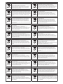
GB CY
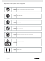
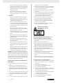
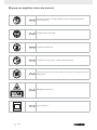
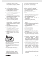
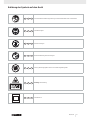
Caution - Read the operating instructions to reduce the risk of inquiry
GB CY
Wear safety goggles!
GB CY
Important! Risk of injury. Never reach into the running saw blade!
0
GB CY
Important! Laser radiation
GB CY
protection class II
GB CY
Wear ear-muffs!
GB CY
Wear a breathing mask!
Explanation of the symbols on the equipment

3
GB/CY
1. Introduction
MANUFACTURER:
scheppach
Fabrikation von Holzbearbeitungsmaschine GmbH
Günzburger Straße 69
D-89335 Ichenhausen
DEAR CUSTOMER,
We hope your new tool brings you much enjoyment and
success.
NOTE:
According to the applicable product liability laws, the
manufacturer of the device does not assume liability for
damages to the product or damages caused by the prod-
uct that occurs due to:
• Improper handling,
• Non-compliance of the operating instructions,
• Repairs by third parties, not by authorized service
technicians,
• Installation and replacement of non-original spare
parts,
• Application other than specied,
• A breakdown of the electrical system that occurs due
to the non-compliance of the electric regulations and
VDE regulations 0100, DIN 57113 / VDE0113.
WE RECOMMEND:
Read through the complete text in the operating instruc-
tions before installing and commissioning the device.
The operating instructions are intended to help the user
to become familiar with the machine and take advan-
tage of its application possibilities in accordance with the
recommendations. The operating instructions contain
important information on how to operate the machine
safely, professionally and economically, how to avoid
danger, costly repairs, reduce downtimes and how to in-
crease reliability and service life of the machine.
In addition to the safety regulations in the operating in-
structions, you have to meet the applicable regulations
that apply for the operation of the machine in your coun-
try. Keep the operating instructions package with the ma-
chine at all times and store it in a plastic cover to protect
it from dirt and moisture. Read the instruction manual
each time before operating the machine and carefully
follow its information. The machine can only be operated
by persons who were instructed concerning the opera-
tion of the machine and who are informed about the as-
sociated dangers. The minimum age requirement must
be complied with.
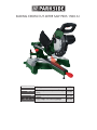
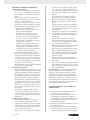
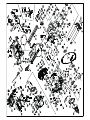
2. Layout (Fig. 1-21)
1. Handle
2. ON/OFF switch
3. Release lever
4. Machine head
5. Movable blade guard
6. Saw blade
7. Clamping device
8. Workpiece support
9. Locking screw for workpiece support
10. Table insert
11. Handle
12. Pointer
13. Scale
14. Turntable
15. Fixed saw table
16. Stop rail
17. Sawdust bag
18. Scale
19. Pointer
20. Locking screw for drag guide
21. Drag guide
22. Locking screw
23. Fastening bolt
24. screw for cutting depth limiter
25. Stop for cutting depth limiter
26. Fastening bolt for turn table
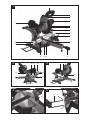
27. Adjustment screw (90°)
28. Adjustment screw (45°)
29. Flange bolt
30. Outer ange
31. Saw shaft lock
32. Inner ange
33. Laser
34. ON/OFF switch for laser
35. Battery compartment
36. Battery compartment cover
37. Guide bar
a) 90° stop angle (not supplied)
b) 45° stop angle (not supplied)
c) spring
d) Allen key, 6 mm
3. Scope of delivery
• Open the packaging and remove the device care-
fully.
• Remove the packaging material as well as the pack-
aging and transport bracing (if available).
• Check that the delivery is complete.
• Check the device and accessory parts for transport
damage.
• If possible, store the packaging until the warranty
period has expired.

4
GB/CY
ATTENTION
The device and packaging materials are not toys!
Children must not be
parts! There is a risk of swallowing and
suffocation!
• Drag, crosscut and mitre Saw
• 2 x Clamping device (7)
• 2 x Workpiece support (8)
• Sawdust bag (17)
• Allen key (d)
• 2 x 1,5 V AAA Battery
• 2 x carbon brush
• Operating manual
4. Intended use
The drag, crosscut and mitre saw is designed to cross-
cut wood and plastic respective of the machine’s size.
The saw is not designed for cutting rewood.
Warning! The supplied saw blade is only intended for
the sawing of wood! Do not use this blade for the saw-
ing of plastic!
The equipment is to be used only for its prescribed
purpose. Any other use is deemed to be a case of mis-
use. The user / operator and not the manufacturer will
be liable for any damage or injuries of any kind caused
as a result of this.
The equipment is to be operated only with suitable
saw blades. It is prohibited to use any type of cutting-
off wheel.
To use the equipment properly you must also observe
the safety information, the assembly instructions and
the operating instructions to be found in this manual.
All persons who use and service the equipment have
to be acquainted with this manual and must be in-
formed about the equipment’s potential hazards. It is
also imperative to observe the accident prevention
regulations in force in your area. The same applies for
the general rules of health and safety at work.
The manufacturer will not be liable for any changes
made to the equipment nor for any damage resulting
from such changes. Even when the equipment is used
as prescribed it is still impossible to eliminate certain
residual risk factors. The following hazards may arise
in connection with the machine’s construction and
design:
• Contact with the saw blade in the uncovered saw
zone.
• Reaching into the running saw blade (cut injuries).
• Kick-back of workpieces and parts of workpieces.
• Saw blade fracturing.
• Catapulting of faulty carbide tips from the saw blade.
• Damage to hearing if ear-muffs are not used as nec-
essary.
• Harmful emissions of wood dust when used in
closed rooms.
Please note that our equipment has not been designed
for use in commercial, trade or industrial applications.
Our warranty will be voided if the equipment is used
in commercial, trade or industrial businesses or for
equivalent purposes.
5. Safety information
Attention! The following basic safety measures must
be observed when using electric tools for protection
against electric shock, and the risk of injury and re.
Read all these notices before using the electric tool
and keep the safety instructions for later reference.
Safe work
1 Keep the work area orderly
– Disorder in the work area can lead to accidents.
2 Take environmental inuences into account
– Do not expose electric tools to rain.
– Do not use electric tools in a damp or wet envi-
ronment.
– Make sure that the work area is well-illuminated.
– Do not use electric tools where there is a risk of
re or explosion.
3 Protect yourself from electric shock
– Avoid physical contact with earthed parts (e.g.
pipes, radiators, electric ranges, cooling units).
4 Keep children away
– Do not allow other persons to touch the equip-
ment or cable, keep them away from your work
area.
5 Securely store unused electric tools
– Unused electric tools should be stored in a dry,
elevated or closed location out of the reach of
children.
6 Do not overload your electric tool
– They work better and more safely in the specied
output range.
7 Use the correct electric tool
– Do not use low-output electric tools for heavy
work.
– Do not use the electric tool for purposes for which
it is not intended. For example, do not use hand-
held circular saws for the cutting of branches or
logs.
– Do not use the electric tool to cut rewood.
8 Wear suitable clothing
– Do not wear wide clothing or jewellery, which can
become entangled in moving parts.
– When working outdoors, anti-slip footwear is
recommended.
– Tie long hair back in a hair net.
9 Use protective equipment
– Wear protective goggles.
– Wear a mask when carrying out dust-creating
work.
10 Connect the dust extraction device
– If connections for dust extraction and a collect-
ing device are present, make sure that they are
connected and used properly.
– Operation in enclosed areas is only permitted
with a suitable extraction system.
11 Do not use the cable for purposes for which it is

5
GB/CY
not intended
– Do not use the cable to pull the plug out of the
outlet. Protect the cable from heat, oil and sharp
edges.
12 Secure the workpiece
– Use the clamping devices or a vice to hold the
workpiece in place. In this manner, it is held
more securely than with your hand.
– An additional support is necessary for long work-
pieces (table, trestle, etc.) in order to prevent the
machine from tipping over.
– Always press the workpiece rmly against
the working plate and stop in order to prevent
bouncing and twisting of the workpiece.
13 Avoid abnormal posture
– Make sure that you have secure footing and
always maintain your balance.
– Avoid awkward hand positions in which a sudden
slip could cause one or both hands to come into
contact with the saw blade.
14 Take care of your tools
– Keep cutting tools sharp and clean in order to be
able to work better and more safely.
– Follow the instructions for lubrication and for tool
replacement.
– Check the connection cable of the electric tool
regularly and have it replaced by a recognised
specialist when damaged.
– Check extension cables regularly and replace
them when damaged.
– Keep the handle dry, clean and free of oil and
grease.
15 Pull the plug out of the outlet
– Never remove loose splinters, chips or jammed
wood pieces from the running saw blade.
– During non-use of the electric tool or prior to
maintenance and when replacing tools such as
saw blades, bits, milling heads.
16 Do not leave a tool key inserted
– Before switching on, make sure that keys and
adjusting tools are removed.
17 Avoid inadvertent starting
– Make sure that the switch is switched off when
plugging the plug into an outlet.
18 Use extension cables for outdoors
– Only use approved and appropriately identied
extension cables for use outdoors.
– Only use cable reels in the unrolled state.
19 Remain attentive
– Pay attention to what you are doing. Remain
sensible when working. Do not use the electric
tool when you are distracted.
20 Check the electric tool for potential damage
– Protective devices and other parts must be care-
fully inspected to ensure that they are fault-free
and function as intended prior to continued use
of the electric tool.
– Check whether the moving parts function fault-
lessly and do not jam or whether parts are dam-
aged. All parts must be correctly mounted and all
conditions must be fullled to ensure fault-free
operation of the electric tool.
– The moving protective hood may not be xed in
the open position.
– Damaged protective devices and parts must be
properly repaired or replaced by a recognised
workshop, insofar as nothing different is speci-
ed in the operating manual.
– Damaged switches must be replaced at a cus-
tomer service workshop.
– Do not use any faulty or damaged connection
cables.
– Do not use any electric tool on which the switch
cannot be switched on and off.
21 ATTENTION!
– Exercise elevated caution for double mitre cuts.
22 ATTENTION!
– The use of other insertion tools and other acces-
sories can entail a risk of injury.
23 Have your electric tool repaired by a qualied
electrician
– This electric tool conforms to the applicable
safety regulations. Repairs may only be per-
formed by an electrician using original spare
parts. Otherwise accidents can occur.
ADDITIONAL SAFETY INSTRUCTIONS
1 Safety precautions
– Warning! Do not use damaged or deformed saw
blades.
– Replace a worn table insert.
– Only use saw blades recommended by the
manufacturer which conform to EN 847-1.
– Make sure that a suitable saw blade for the ma-
terial to be cut is selected.
– Wear suitable personal protective equipment.
This includes:
– Hearing protection to avoid the risk of becom-
ing hearing impaired,
– Respiratory protection to avoid the risk of
inhaling harmful dust,
– Wear gloves when handling saw blades and
rough materials. Carry saw blades in a con-
tainer whenever practical.
– Wear goggles. Sparks generated during work
or splinters, chippings and dust coming from
the device can lead to loss of eyesight.
– Connect a dust collecting device to the electric
tool when sawing wood. The emission of dust
is inuenced, among other things, by the type
of material to be processed, the signicance of
local separation (collection or source) and the
correct setting of the hood/guide plates/guides.
– Do not use saw blades made of high-speed alloy
steel (HSS steel).
2 Maintenance and repair
– Pull out the mains plug for any adjustment or
repair tasks.
– The generation of noise is inuenced by various
factors, including the characteristics of saw
blades, condition of saw blade and electric

6
GB/CY
tool. Use saw blades which were designed for
reduced noise development, insofar as possible.
Maintain the electric tool and tool attachments
regularly and if necessary, initiate repairs in
order to reduce noise.
– Report faults on the electric tool, protective
devices or the tool attachment to the person
responsible for safety as soon as they are dis-
covered.
3 Safe work
– Only use saw blades for which the maximum
permissible speed is not lower than the maxi-
mum spindle speed of table saws and which are
suitable for the material to be cut.
– Make sure that the saw blade does not touch
the rotary table in any position by pulling out the
mains plug and rotating the saw blade by hand
in the 45° and 90° position. If necessary, read-
just the saw head.
– When transporting the electric tool, only use
the transport devices. Never use the protective
devices for handling or transport.
– Make sure that the lower part of the saw blade is
covered during transport, e.g. by the protective
device.
– Be sure to only use spacers and spindle rings
specied by the manufacturer as suitable for the
intended purpose.
– The oor around the machine must be level,
clean and free of loose particles, such as chips
and cutting residues.
– Do not remove any cutting residues or other
parts of workpieces from the cutting zone while
the machine is running and the saw unit is not
at rest.
– Make sure that the machine is always secured
on a workbench or a table if at all possible.
– Support long workpieces (e.g. with a roller table)
to prevent them sagging at the end of a cut.
Warning! This electric tool generates an electromag-
netic eld during operation. This eld can impair active
or passive medical implants under certain conditions. In
order to prevent the risk of serious or deadly injuries, we
recommend that persons with medical implants consult
with their physician and the manufacturer of the medical
implant prior to operating the electric tool.
SAFETY INSTRUCTIONS FOR THE HANDLING OF
SAW BLADES
1 Only use insertion tools if you have mastered their
use.
2 Observe the maximum speed. The maximum
speed specied on the insertion tool may not be
exceeded. If specied, observe the speed range.
3 Observe the motor / saw blade direction of rota-
tion.
4 Do not use any insertion tools with cracks. Sort out
cracked insertion tools. Repairs are not permitted.
5 Clean grease, oil and water off of the clamping
surfaces.
6 Do not use any loose reducing rings or bushes for
the reducing of holes on saw blades.
7 Make sure that xed reducer rings for securing the
insertion tool have the same diameter and have at
least 1/3 of the cutting diameter.
8 Make sure that xed reducer rings are parallel to
each other.
9 Handle insertion tool with caution. They are ideally
stored in the originally package or special contain-
ers. Wear protective gloves in order to improve
grip and to further reduce the risk of injury.
10 Prior to the use of insertion tools, make sure that
all protective devices are properly fastened.
11 Prior to use, make sure that the insertion tool
meets the technical requirements of this electric
tool and is properly fastened.
12 Only use the supplied saw blade for cutting wood,
never for the processing of metals.
Attention: Laser radiation
Do not stare into the beam
Class 2 laser
Protect yourself and you environment from acci-
dents using suitable precautionary measures!
• Do not look directly into the laser beam with unpro-
tected eyes.
• Never look into the path of the beam.
• Never point the laser beam towards reecting sur-
faces and persons or animals. Even a laser beam
with a low output can cause damage to the eyes.
• Caution - methods other than those specied here
can result in dangerous radiation exposure.
• Never open the laser module. Unexpected exposure
to the beam can occur.
• If the mitre saw is not used for an extended period
of time, the batteries should be removed.
• The laser may not be replaced with a different type
of laser.
• Repairs of the laser may only be carried out by the
laser manufacturer or an authorised representative.
Safety instructions for handling batteries
1 Always make sure that the batteries are inserted
with the correct polarity (+ and –), as indicated on
the battery.
2 Do not short-circuit batteries.
3 Do not charge non-rechargeable batteries.
4 Do not overcharge batteries!
5 Do not mix old and new batteries or batteries of
different types or manufacturers! Replace an entire
set of batteries at the same time.
6 Immediately remove used batteries from the device
and dispose of them properly!
7 Do not allow batteries to heat up!
8 Do not weld or solder directly on batteries!
9 Do not dismantle batteries!
0

7
GB/CY
10 Do not allow batteries to deform!
11 Do not throw batteries into re!
12 Keep batteries out of the reach of children.
13 Do not allow children to replace batteries without
supervision!
14 Do not keep batteries near re, ovens or other
sources of heat. Do not use batteries in direct sun-
light or store them in vehicles in hot weather.
15 Keep unused batteries in the original packaging and
keep them away from metal objects. Do not mix
unpacked batteries or toss them together! This can
lead to a short-circuit of the battery and thus dam-
age, burns or even the risk of re.
16 Remove batteries from the equipment when it will
not be used for an extended period of time, unless
it is for emergencies!
17 NEVER handle batteries that have leaked without
appropriate protection. If the leaked uid comes into
contact with your skin, the skin in this area should be
rinsed off under running water immediately. Always
prevent the uid from coming into contact with the
eyes and mouth. In the event of contact, please seek
immediate medical attention.
18 Clean the battery contacts and corresponding con-
tacts in the device prior to inserting the batteries:
6. Technical data
AC motor 220 - 240 V ~ 50Hz
Power 1500 Watt
Operating mode S6 25%*
Idle speed n
0
5000 min
-1
Carbide saw blade ø 210 x ø 30 x 2,6 mm
Number of teeth 24
Swivel range -45° / 0°/ +45°
Mitre cut 0° bis 45° nach links
Saw width at 90° 340 x 58 mm
Saw width at 45° 240 x 58 mm
Saw width at 2 x 45°
(double mitre cut)
240 x 32 mm
Protection class II
Weight approx. 17 kg
Laser class 2
Wavelength of laser 650 nm
Laser output ≤ 1 mW
Laser module power
supply
2 x 1,5 V Micro (AAA)
* S6, continuous operation periodic duty.
Identical duty cycles with a period at load followed
by a period at no load. Running time 10 minutes;
duty cycle is 25% of the running time.
The work piece must have a minimum height of 3mm
and a minimum width of 10 mm.
Make sure that the workpiece is always secured with
the clamping device.
Noise and vibration
Total vibration values determined in accordance with
EN 61029.
sound pressure level L
pA
99.6 dB(A)
uncertainty K
pA
3 dB
sound power level L
WA
112.6 dB(A)
uncertainty K
WA
3 dB
Wear hearing protection.
The effects of noise can cause a loss of hearing. Total
vibration values (vector sum - three directions) deter-
mined in accordance with EN 61029.
Vibration emission value a
h
4.51 m/s²
uncertainty K 1,5 m/s²
- The specied vibration value was established in ac-
cordance with a standardized testing method. It may
change according to how the electric equipment is
used and may exceed the specied value in exceptio-
nal circumstances;
- The specied vibration value can be used to compare
the equipment with other electric power tools.
- The specied vibration value can be used for initial
assessment of a harmful effect.
Reduce noise generation and vibration to a mini-
mum!
- Use only equipment that is in perfect condition.
- Maintain and clean the equipment regularly.
- Adopt your way of working to the equipment.
- Do not overload the equipment.
- Have the equipment checked if necessary.
- Switch off the equipment when not in use.
Residual risks
The machine has been built according to the state of
the art and the recognised technical safety require-
ments. However, individual residual risks can arise
during operation.
• Health hazard due to electrical power, with the use of
improper electrical connection cables.
• Furthermore, despite all precautions having been met,
some non-obvious residual risks may still remain.
• Residual risks can be minimised if the „safety instruc-
tions“ and the „Proper use“ are observed along with
the whole of the operating instructions.
• Do not load the machine unnecessarily: excessive
pressure when sawing will quickly damage the saw
blade, which results in reduced output of the machine
in the processing and in cut precision.
• When cutting plastic material, please always use
clamps: the parts which should be cut must always
be xed between the clamps.
• Avoid accidental starting of the machine: the oper-
ating button may not be pressed when inserting the
plug in an outlet.
• Use the tool that is recommended in this manual. In do-

8
GB/CY
ing so, your mitre saw provides optimal performance.
• Hands may never enter the processing zone when
the machine is in operation. Release the handle but-
ton and switch off the machine prior to any operations.
7. Before starting the equipment
• The equipment must be set up where it can stand
securely, i.e. it should be bolted to a workbench, a
universal base frame or similar.
• All covers and safety devices have to be properly t-
ted before the equipment is switched on.
• It must be possible for the blade to run freely.
• When working with wood that has been processed
before, watch out for foreign bodies such as nails or
screws, etc.
• Before you press the ON/OFF switch check that the
saw blade is tted correctly. Moving parts must run
smoothly.
• Before you connect the equipment to the power sup-
ply make sure the data on the rating plate are denti-
cal to the mains data.
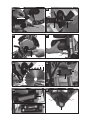
8. Attachment and operation
8.1 Attaching the saw (Fig1/2/3/4/5)
• In order to adjust the rotary table (14) loosen the set
screw (26) approx. 2 turns.
• Turn the rotary table (14) and pointer (12) to the de-
sired angle measurement on the scale (13) and se-
cure with the set screw (26).
• Pressing the machine head (4) lightly downwards
and removing the locking bolt (23) from the motor
bracket at the same time disengages the saw from
the lowest position.
• Swing the machine head (4) up until the release le-
ver (3) latches into place.
• It is possible to secure the clamping device (7) to the
left or right on the stationary saw bench (15).
• Attach the workpiece supports (8) to the xed saw
table (15) as shown in Figure 5 and fasten with the
screw (9).
• It is possible to tilt the machine head (4) a max. 45°
to the left by loosening the set screw (22).
8.2 Precision adjustment of the stop for crosscut
90° (Fig. 1/6/7)
• No stop angle included.
• Lower the machine head (4) and secure using the
locking bolt (23).
• Loosen the set screw (22).
• Position the angle stop (a) between the saw blade
(6) and the rotary table (14).
• Adjust the adjusting screw (27) until the angle be-
tween the saw blade (6) and rotary table (14) is 90°.
• It is not necessary to x this setting because it is
maintained by the spring pretension.
• Subsequently check the position of the angle indi-
cator. If necessary loosen the pointer (19) using a
Philips screwdriver, set to position 0° on the angle
scale (18) and re-tighten the retaining screw.
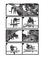
8.3 Cross cut 90° and turntable 0° (Fig.8)
In the case of cutting widths up to approx. 100 mm it
is possible to x the traction function of the saw with
the set screw (20) in the rear position. In this position
the machine can be operated in cross cutting mode. If
the cutting width is over 100 mm then it is necessary
to ensure that the set screw (20) is loose and the ma-
chine head (4) can move.
• Move the machine head (4) to its upper position.
• Use the handle (3) to push back the machine head
(4) and x it in this position if required (dependent
on the cutting width).
• Place the piece of wood to be cut at the stop rail
(16) and on the turntable (14).
• Lock the material with the clamping device (7) on
the xed saw table (15) to prevent the material from
moving during the cutting operation.
• Push down the release lever (3) to release the ma-
chine head (4).
• Press the ON/OFF switch (2) to start the motor.
• With the drag guide (21) xed in place:
• use the handle (1) to move the machine head (4)
steadily and with light pressure downwards until the
saw blade (6) has completely cut through the work
piece.
• With the drag guide (21) not xed in place:
• pull the machine head (4) all the way to the front.
Lower the handle (1) to the very bottom by apply-
ing steady and light downward pressure. Now push
the machine head (4) slowly and steadily to the
very back until the saw blade (6) has completely cut
through the work piece.
• When the cutting operation is completed, move the
machine head (4) back to its upper (home) position
and release the ON/OFF button (2).
Attention! The machine executes an upward stroke
automatically due to the return spring, i.e. do not re-
lease the handle (1) after completing the cut; instead
allow the machine head to move upwards slowly
whilst applying light counter pressure.
8.4 Cross cut 90° and turntable 0° - 45° (Fig. 9)
The crosscut saw can be used to make crosscuts of 0°
-45° to the left and 0° -45° to the right in relation to the
stop rail.
• Loosen set screw (26).
• Use the handle (11) to adjust the rotary table (14)
to the desired angle. The pointer (12) on the rotary
table must match the desired angle on the scale (13)
on the xed saw table (15).
• Re-tighten the set screw (26) in order to secure the
rotary table (14).
• Cut as described under section 8.3.
8.5 Precision adjustment of the stop for mitre cut
45° (Fig. 1/10/11)
• No stop angle included.
• Lower the machine head (4) and secure using the
locking bolt (23).
• Fix the rotary table (14) in the 0° position.
• Loosen the set screw (22) and use the handle (1) to

9
GB/CY
angle the machine head (4) 45° to the left.
• 45° - position angle stop (b) between the saw blade
(6) and rotary table (14).
• Adjust the adjusting screw (28) until the angle be-
tween the saw blade (6) and rotary table (14) is pre-
cisely 45°.
• It is not necessary to x this setting because it is
maintained by the spring pretension.
• Subsequently check the position of the angle indi-
cator. If necessary loosen the pointer (19) using a
Philips screwdriver, set to position 0° on the angle
scale (18) and re-tighten the retaining screw.
8.6 Mitre cut 0°- 45° and turntable 0° (Fig. 1/2/12)
The crosscut saw can be used to make mitre cuts of
0° - 45° in relation to the work face.
• Move the machine head (4) to the top position.
• Fix the rotary table (14) in the 0° position.
• Loosen the set screw (22) and use the handle (1)
to angle the machine head (4) to the left, until the
pointer (19) indicates the desired angle measure-
ment on the scale (18).
• Re-tighten the xing screw (22).
• Cut as described in section 8.3.
8.7 Mitre cut 0°- 45° and turntable 0°- 45°
(Fig. 2/4/13)
The crosscut saw can be used to make mitre cuts to
the left of 0°- 45° in relation to the work face and, at
the same time, 0° - 45° to the left or 0° - 45° to the
right in relation to the stop rail (double mitre cut).
• Move the machine head (4) to its upper position.
• Release the rotary table (14) by loosening the set
screw (26).
• Using the handle (11), set the rotary table (14) to the
desired angle (refer also to point 8.4 in this regard).
• Re-tighten the set screw (26) in order to secure the
rotary table.
• Undo the locking screw (22) and use the handle (1)
to tilt the machine head (4) to the left until it coin-
cides with the required angle value (in this connec-
tion see also section 8.6).
• Re-tighten the xing screw (22).
• Cut as described under section 8.3.
8.8 Limiting the cutting depth (Fig. 3/14)
• The cutting depth can be innitely adjusted using the
screw (24). To do this loosen the knurled nut on the
screw (24). Move the stop for the cutting depth limi-
tre (25) to the outside. Turn the screw (24) in or out
to set the required cutting depth. Then re-tighten the
knurled nut on the screw (24).
• Check the setting by completing a test cut.
8.9 Sawdust bag (Fig. 1)
The saw is equipped with a debris bag (17) for saw-
dust and chips.
Squeeze together the metal ring on the dust bag and
attach it to the outlet opening in the motor area.
The debris bag (17) can be emptied by means of a zip-
per at the bottom.
8.10 Changing the saw blade (Fig. 15/16/17/18)
Remove the power plug!
Important.
Wear safety gloves when changing the saw blade.
Risk of injury!
• Swing up the machine head (5).
• Undo the screw (e) on the guide bar (37), so that it
can move freely and be pivoted downwards.
• Press the release lever (3). Swing up the saw blade
guard (6) to the point where the recess in the saw
blade guard (6) is above the ange bolt (31).
• Press the saw shaft lock (4) with one hand. With the
other hand insert the allen key (d) in the ange bolt
(31).
• Hold the Allen key (d) and slowly close the saw bla-
de guard until it touches the Allen key.
• Firmly press the saw shaft lock (4) and slowly rotate
the ange bolt (31) in clockwise direction. The saw
shaft lock (4) engages after no more than one rotation.
• Now, using a little more force, slacken the ange
bolt (31) in the clockwise direction.
• Turn the ange screw (31) right out and remove the
external ange (32).
• Take the blade (7) off the inner ange (38) and pull
out downwards.
• Carefully clean the ange screw (31), outer ange
(32) and inner ange (38).
• Fit and fasten the new saw blade (7) in reverse or-
der.
• Important! The cutting angle of the teeth, in other
words the direction of rotation of the saw blade (7)
must coincide with the direction of the arrow on the
housing.
• Move the guide bar (37) into position and tighten the
screw (e) again.
• Before continuing your work make sure that all safe-
ty devices are in good working condition.
• Important! Every time that you change the saw
blade (7), check to see that it spins freely in the ta-
ble insert (11) in both perpendicular and 45° angle
settings.
• Important! The work to change and align the saw
blade (7) must be carried out correctly.
8.11 Using the laser (Fig. 3/19/20)
• To switch on: Move the ON/OFF switch of the laser
(34) to the “1” position. A laser line is projected onto
the material you wish to process, providing an exact
guide for the cut.
• To switch off: Move the ON/OFF switch of the laser
(34) to the “0” position.
• Replacing the battery: Switch off the laser (33).
Remove the battery compartment cover (36). Re-
move the batteries and replace with new batteries
(2 x 1.5 Volt Type LR 03 Micro, AAA) Check that
the battery terminals are positioned correctly when
inserting new batteries. Close the battery compart-
ment (35) again.

10
GB/CY
8.12 Adjusting the laser (Fig. 21)
If the laser (33) ceases to indicate the correct cutting
line, you can readjust the laser. To do so, open the
screws (38) and set the laser by moving sideways to
that the laser beam strikes the teeth of the saw blade
(6).
9. Transport
• Tighten the set screw (26) in order to lock the rotary
table (14)
• Activate the release lever (3), press the machine
head (4) downwards and secure with the safety pin
(23). The saw is now locked in its bottom position.
• Fix the saw’s drag function with the locking screw for
drag guide (20) in rear position.
• Carry the equipment by the xed saw table (15).
• When reassembling the equipment proceed as de-
scribed under section 7.1.
10. Maintenance
m Warning! Prior to any adjustment, maintenance or
service work disconnect the mains power plug!
General maintenance measures
Wipe chips and dust off the machine from time to time
using a cloth. In order to extend the service life of the
tool, oil the rotary parts once monthly. Do not oil the
motor.
When cleaning the plastic do not use corrosive products.
Brush inspection
Check the carbon brushes after the rst 50 operating
hours with a new machine, or when new brushes have
been tted. After carrying out the rst check, repeat the
check every 10 operating hours.
If the carbon is worn to a length of 6 mm, or if the spring
or contact wire are burned or damaged, it is necessary
to replace both brushes. If the brushes are found to be
usable following removal, it is possible to reinstall them.
11. Storage
Store the device and its accessories in a dark, dry and
frost-proof place that is inaccessible to children. The
optimum storage temperature is between 5 and 30˚C.
Store the electrical tool in its original packaging.
Cover the electrical tool in order to protect it from dust
and moisture.
Store the operating manual with the electrical tool.
12. Electrical connection
The electrical motor installed is connected and
ready for operation. The connection complies with
the applicable VDE and DIN provisions.
The customer‘s mains connection as well as the
extension cable used must also comply with these
regulations.
• The product meets the requirements of
EN 61000-3-11 and is subject to special connection
conditions. This means that use of the product at
any freely selectable connection point is not allowed.
• Given unfavorable conditions in the power supply the
product can cause the voltage to uctuate temporarily.
• The product is exclusively intended for use at con-
nection points that have a continuous current-carry-
ing capacity of at least 100 A per phase.
• As the user, you are required to ensure, in consulta-
tion with your electric power company if necessary,
that the connection point at which you wish to oper-
ate the product meets the specied requirements.
Important information
n the event of an overloading the motor will switch
itself off. After a cool-down period (time varies) the mo-
tor can be switched back on again.
Damaged electrical connection cable
The insulation on electrical connection cables is often
damaged.
This may have the following causes:
• Passage points, where connection cables are
passed through windows or doors.
• Kinks where the connection cable has been improp-
erly fastened or routed.
• Places where the connection cables have been cut
due to being driven over.
• Insulation damage due to being ripped out of the
wall outlet.
• Cracks due to the insulation ageing.
Such damaged electrical connection cables must not
be used and are life-threatening due to the insulation
damage.
Check the electrical connection cables for damage
regularly. Make sure that the connection cable does
not hang on the power network during the inspection.
Electrical connection cables must comply with the ap-
plicable VDE and DIN provisions. Only use connection
cables with the marking „H05VV-F“.
The printing of the type designation on the connection
cable is mandatory.
AC motor
• The mains voltage must be 230 V~
• Extension cables up to 25 m long must have a
cross-section of 1.5 mm2.
Connections and repairs of electrical equipment
may only be carried out by an electrician.
Please provide the following information in the event of
any enquiries:
• Type of current for the motor
• Machine data - type plate
• Machine data - type plate

11
GB/CY
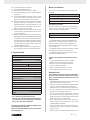
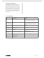
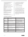
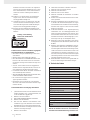
14. Troubleshooting
Fault Possible cause Remedy
Motor does not work Motor, cable or plug defective, fuses burnt Arrange for inspection of the machine by a
specialist. Never repair the motor yourself. Danger!
Check fuses and replace as necessary
The motor starts up
slowly and does not
reach operating speed.
Voltage too low, coils damaged, capacitor
burnt
Contact the utility provider to check the voltage.
Arrange for inspection of the motor by a specialist.
Arrange for replacement of the capacitor by a
specialist
Motor makes excessive
noise
Coils damaged, motor defective Arrange for inspection of the motor by a specialist
The motor does not
reach its full power.
Circuits in the network are overloaded (lamps,
other motors, etc.)
Do not use any other equipment or motors on the
same circuit
Motor overheats easily. Overloading of the motor, insufcient cooling
of the motor
Avoid overloading the motor while cutting, remove
dust from the motor in order to ensure optimal
cooling of the motor
Reduced cutting power
when sawing
Saw blade too small (ground too much) Readjust end stop of the saw unit
Saw cut is rough or
wavy
Saw blade dull, tooth shape not appropriate for
the material thickness
Resharpen saw blade and/or use suitable saw blade
Workpiece pulls away
and/or splinters
Excessive cutting pressure and/or saw blade
not suitable for use
Insert suitable saw blade
13. Disposal and recycling
The equipment is supplied in packaging to prevent it
from being damaged in transit. The raw materials in
this packaging can be reused or recycled. Never place
batteries in your household refuse, in re or in water.
Batteries should be collected, recycled or disposed of
by environment-friendly means. The equipment and
its accessories are made of various types of material,
such as metal and plastic. Defective components must
be disposed of as special waste. Ask your dealer or
your local council.

12
GB/CY
All of our products undergo strict quality checks to ensure that they reach you in perfect condition. In the unlikely event that your
device develops a fault, please contact our service department at the address shown on this guarantee card. Of course, if you
would prefer to call us then we are also happy to offer our assistance under the service number printed below. Please note the
following terms under which guarantee claims can be made:
• These guarantee terms cover additional guarantee rights and do not affect your statutory warranty rights. We do not charge
you for this guarantee.
• Our guarantee only covers problems caused by material or manufacturing defects, and it is restricted to the rectication of
these defects or replacement of the device. Please note that our devices have not been designed for use in commercial, trade
or industrial applications. Consequently, the guarantee is invalidated if the equipment is used in commercial, trade or industrial
applications or for other equivalent activities. The following are also excluded from our guarantee: compensation for transport
damage, damage caused by failure to comply with the installation/assembly instructions or damage caused by unprofessional
installation, failure to comply with the operating instructions (e.g. connection to the wrong mains voltage or current type), mis-
use or inappropriate use (such as overloading of the device or use of non-approved tools or accessories), failure to comply with
the maintenance and safety regulations, ingress of foreign bodies into the device (e.g. sand, stones or dust), effects of force or
external inuences (e.g. damage caused by the device being dropped) and normal wear resulting from proper operation of the
device.
The guarantee is rendered null and void if any attempt is made to tamper with the device.
• The guarantee is valid for a period of 3 years starting from the purchase date of the device. Guarantee claims should be
submitted before the end of the guarantee period within two weeks of the defect being noticed. No guarantee claims will be
accepted after the end of the guarantee period. The original guarantee period remains applicable to the device even if repairs
are carried out or parts are replaced. In such cases, the work performed or parts tted will not result in an extension of the
guarantee period, and no new guarantee will become active for the work performed or parts tted. This also applies when an
on-site service is used.
• In order to assert your guarantee claim, please send your defective device postage-free to the address shown below. Please
enclose either the original or a copy of your sales receipt or another dated proof of purchase. Please keep your sales receipt in
a safe place, as it is your proof of purchase. It would help us if you could describe the nature of the problem in as much detail
as possible. If the defect is covered by our guarantee then your device will either be repaired immediately and returned to you,
or we will send you a new device.
Of course, we are also happy offer a chargeable repair service for any defects which are not covered by the scope of this guar-
antee or for units which are no longer covered. To take advantage of this service, please send the device to our service address.

13
GR/CY
1.
Εισαγωγή 15
2.
Περιγραφή της συσκευής 15
3.
Παραδοτέο υλικό 15-16
4.
Ενδεδειγμένη χρήση 16
5.
Σημαντικές υποδείξεις 16-19
6.
Τεχνικά χαρακτηριστικά 20
7.
Πριν τη θέση σε λειτουργία 21
8.
Τοποθέτηση και χειρισμός 21-23
9.
Μεταφορά 23
10.
Συντήρηση 23
11.
Αποθήκευση 23
12.
Ύνδεση στο ηλεκτρικό ρεύμα 23-24
13.
Διάθεση στα απορρίμματα και
επαναχρησιμοποίηση
24
14.
Αντιμετώπιση προβλημάτων 25
15.
Εγγυηση 26
16.
Δήλωση συμμόρφωσης 56

14
GR/CY
GR CY
Πριν θέσετε τη συσκευή σε λειτουργία, διαβάστε και τηρείτε τις οδηγίες χειρισμού και τις
υποδείξεις ασφαλείας!
GR CY
Να φοράτε προστατευτικά γυαλιά!
GR CY
Προσοχή! Κίνδυνος τραυματισμού! Μην τοποθετείτε τα χέρια σας στην περιοχή της κινούμενης
λάμας πριονιού!
0
GR CY
Ακτινοβολία λέιζερ
GR CY
Κλάση προστασίας II
GR CY
Να φοράτε προστασία ακοής!
GR CY
Σε περίπτωση εκπομπής σκόνης, να φοράτε προστασία αναπνοής!

15
GR/CY
scheppach
Fabrikation von Holzbearbeitungsmaschine GmbH
Günzburger Straße 69
D-89335 Ichenhausen
Σας ευχόμαστε πολλή ευχαρίστηση και καλή επιτυχία
κατά την εργασία με τη νέα σας συσκευή.
Σύμφωνα με την υφιστάμενη νομοθεσία περί ευθύνης
προϊόντος, ο κατασκευαστής αυτής της συσκευής δεν ευ-
θύνεται για ζημιές που προκύπτουν από ή σε σχέση με
αυτή τη συσκευή σε περίπτωση:
• ανάρμοστου χειρισμού,
• μη συμμόρφωσης με τις οδηγίες χρήσης,
• επισκευών από τρίτους, μη εξουσιοδοτημένων εξειδι-
κευμένων εργατών,
• εγκατάστασης και αντικατάστασης μη-αυθεντικών
ανταλλακτικών,
• ανάρμοστης χρήσης,
• βλαβών του ηλεκτρικού συστήματος λόγω της μη συμ-
μόρφωσης με τις ηλεκτρικές προδιαγραφές και τους
κανονισμούς VDE0100, DIN 57113 / VDE 0113.
Διαβάστε ολόκληρο το κείμενο των οδηγιών λειτουργίας
πριν από τη συναρμολόγηση και τη λειτουργία της συ-
σκευής.
Αυτές οι οδηγίες λειτουργίας προορίζονται να σας δι-
ευκολύνουν να εξοικειωθείτε με τη συσκευή σας και να
χρησιμοποιήσετε όλες τις δυνατότητες για τις οποίες
προορίζεται.
Οι οδηγίες λειτουργίας περιέχουν σημαντικές σημειώ-
σεις για το πώς να εργαστείτε με ασφάλεια, κατάλληλα
και οικονομικά με τη μηχανή σας και πώς να αποφύγετε
κινδύνους, να εξοικονομήσετε δαπάνες επισκευής, να
μειώσετε το χρόνο διακοπής και να αυξήσετε την αξιοπι-
στία και τη διάρκεια ζωής της μηχανής.
Εκτός από τους κανονισμούς ασφάλειας που περιλαμ-
βάνονται στο παρόν, πρέπει εν πάση περιπτώσει να
συμμορφωθείτε με τους εφαρμοστέους κανονισμούς της
χώρας σας όσον αφορά στη λειτουργία της μηχανής.
Τοποθετήστε τις οδηγίες λειτουργίας σε ένα διαφανή
πλαστικό φάκελο ώστε να τις προστατεύσετε από ρύ-
πους και υγρασία και αποθηκεύστε τις κοντά στη μηχα-
νή. Οι οδηγίες πρέπει να διαβαστούν και να τηρούνται
προσεκτικά από κάθε χειριστή πριν από την εκκίνηση
της εργασίας. Μόνο τα πρόσωπα που έχουν εκπαιδευ-
θεί ως προς τη χρήση της μηχανής και έχουν ενημερωθεί
για τους σχετικούς κινδύνους και απειλές έχουν την άδεια
να χρησιμοποιήσουν τη μηχανή. Η απαραίτητη ελάχιστη
ηλικία πρέπει να πληρείται.
Εκτός από τις σημειώσεις ασφάλειας που περιλαμβάνο-
νται στις παρούσες οδηγίες λειτουργίας και τους ιδιαίτε-
ρους κανονισμούς της χώρας σας, πρέπει να τηρούνται
οι γενικά αναγνωρισμένοι τεχνικοί κανόνες για τη λει-
τουργία ξυλουργικών μηχανών.
Δεν αναλαμβάνουμε καμία ευθύνη για ατυχήματα ή ζη-
μιές που θα προκύψουν από μη τήρηση αυτών των οδη-
γιών και των υποδείξεων ασφαλείας.
1-21)
1. Χειρολαβή
2. Διακόπτης ενεργοποίησης/απενεργοποίησης
3. Μοχλός απομανδάλωσης
4. Κεφαλή μηχανής
5. Κινητή προστασία πριονοδίσκου
6. Δίσκος
7. Σύστημα σύσφιξης
8. Θέση για κατεργαζόμενο αντικείμενο
9. Βίδα ακινητοποίησης για επιφάνεια τοποθέτησης
κατεργαζόμενου αντικειμένου
10. Ένθετο πάγκου εργασίας
11. Χειρολαβή
12. Δείκτης
13. Κλίμακα
14. Περιστρεφόμενος πάγκος
15. Μόνιμος πάγκος πριονιού
16. Ράβδος-οδηγός
17. Σάκος συλλογής ροκανιδιών
18. Κλίμακα
19. Δείκτης
20. Βίδα ακινητοποίησης έλξης
21. Έλξη
22. Βίδα ασφάλισης
23. Μπoυλόνι ασφάλειας
24. Βίδα-πεταλούδα για όριο βάθους κοπής
25. Τέρμα για όριο βάθους κοπής
26. Βίδα ακινητοποίησης για περιστρεφόμενη βάση
27. Βίδα ρύθμισης (90°)
28. Βίδα ρύθμισης (45°)
29. Βίδα φλάντζας
30. Εξωτερική φλάντζα
31. Ακινητοποίηση άξονα πριονιού
32. Εσωτερική φλάντζα
33. Λέιζερ
34. Διακότπης ενεργοποίησης / απενεργοποίησης
λαίηζερ
35. Θήκη μπαταριών
36. Καπάκι θήκης μπαταριών
37. Βραχίονας οδήγησης
a) 90° γωνία-οδηγός (δεν συμπαραδίδεται)
b) 45° γωνία-οδηγός (δεν συμπαραδίδεται)
c) Ελατήριο
d) Κλειδί άλλεν, 6 mm
• Ανοίξτε τη συσκευασία και αφαιρέστε προσεκτικά τη
συσκευή.
• Απομακρύνετε το υλικό συσκευασίας καθώς και τις
ασφάλειες συσκευασίας/και μεταφοράς (εφόσον
υπάρχουν).
• Ελέγξτε εάν είναι πλήρης η παράδοση.
• Ελέγξτε τη συσκευή και τα αξεσουάρ για τυχόν
ζημιές από τη μεταφορά.
Seite wird geladen ...
Seite wird geladen ...
Seite wird geladen ...
Seite wird geladen ...
Seite wird geladen ...
Seite wird geladen ...
Seite wird geladen ...
Seite wird geladen ...
Seite wird geladen ...
Seite wird geladen ...
Seite wird geladen ...
Seite wird geladen ...
Seite wird geladen ...
Seite wird geladen ...
Seite wird geladen ...
Seite wird geladen ...
Seite wird geladen ...
Seite wird geladen ...
Seite wird geladen ...
Seite wird geladen ...
Seite wird geladen ...
Seite wird geladen ...
Seite wird geladen ...
Seite wird geladen ...
Seite wird geladen ...
Seite wird geladen ...
Seite wird geladen ...
Seite wird geladen ...
Seite wird geladen ...
Seite wird geladen ...
Seite wird geladen ...
Seite wird geladen ...
Seite wird geladen ...
Seite wird geladen ...
Seite wird geladen ...
Seite wird geladen ...
Seite wird geladen ...
Seite wird geladen ...
Seite wird geladen ...
Seite wird geladen ...
Seite wird geladen ...
Seite wird geladen ...
Seite wird geladen ...
Seite wird geladen ...
-
 1
1
-
 2
2
-
 3
3
-
 4
4
-
 5
5
-
 6
6
-
 7
7
-
 8
8
-
 9
9
-
 10
10
-
 11
11
-
 12
12
-
 13
13
-
 14
14
-
 15
15
-
 16
16
-
 17
17
-
 18
18
-
 19
19
-
 20
20
-
 21
21
-
 22
22
-
 23
23
-
 24
24
-
 25
25
-
 26
26
-
 27
27
-
 28
28
-
 29
29
-
 30
30
-
 31
31
-
 32
32
-
 33
33
-
 34
34
-
 35
35
-
 36
36
-
 37
37
-
 38
38
-
 39
39
-
 40
40
-
 41
41
-
 42
42
-
 43
43
-
 44
44
-
 45
45
-
 46
46
-
 47
47
-
 48
48
-
 49
49
-
 50
50
-
 51
51
-
 52
52
-
 53
53
-
 54
54
-
 55
55
-
 56
56
-
 57
57
-
 58
58
-
 59
59
-
 60
60
-
 61
61
-
 62
62
-
 63
63
-
 64
64


Parkside PZKS 1500 A1 Operating And Safety Instructions Manual
- Typ
- Operating And Safety Instructions Manual
Verwandte Artikel
-
Parkside PZKS 1500 B2 - IAN 295934 Bedienungsanleitung
-
Parkside PKS 1500 A2 Operating And Safety Instructions, Translation Of Original Operating Manual
-
-
-
-
-
-
-
Parkside PKZS 2000 A1 Bedienungsanleitung
-
Lidl PZKS 1500 B2 Bedienungsanleitung
Andere Dokumente
-
Scheppach MT210 Benutzerhandbuch
-
Scheppach HM140L Translation Of Original Instruction Manual
-
Scheppach HM120L Original Instruction Manual
-
Evolution Power Tools RAGE3 Benutzerhandbuch
-
Evolution Rage 3-S Benutzerhandbuch
-
-