
Refer All Communications to the Nearest
Ingersoll-- Rand Office or Distributor.
Ingersoll--Rand Company 2001
PrintedinU.S.A.
04577649
Form P7486--EU
Edition 2
November, 2001
INSTRUCTIONS FOR
MODELS 2131A, 2131AS, 2131AS--2,
2131QT AND 2131QT-2
ULTRA DUTY AUTOMOTIVE IMPACT WRENCHES
The 2131 series of Impact Wrenches are designed for use in general automotive repair,
tire service and heavy duty fleet applications.
Ingersoll--Rand is not responsible for customer modification of tools forapplications on
which Ingersoll--Rand was not consulted.
IMPORTANT SAFETY INFORMATION ENCLOSED.
READ THIS MANUAL BEFORE OPERATING TOOL.
IT IS THE RESPONSIBILITY OF THE EMPLOYER TO PLACE THE INFORMATION
IN THIS MANUAL INTO THE HANDS OF THE OPERATOR.
FAILURE TO OBSERVE THE FOLLOWING WARNINGS COULD RESULT IN INJURY.
PLACING TOOL IN SERVICE
• Always operate, inspect and maintain this tool in
accordance with all regulations (local, state, federal
and country), that may apply to hand held/hand
operated pneumatic tools.
• For safety, top performance, and maximum
durability of parts, operate this too l at 90 psig
(6.2 bar/620 kPa) maximum air pressure at the
inlet.
• Always turn off the air supply and disconnect the
air supply hose before installing, removing or
adjusting any accessory on this tool, or before
performing any maintenance on this tool.
• Do not use damaged, frayed o r deteriorated air
hoses and fittings.
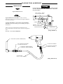
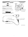
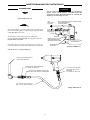
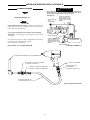
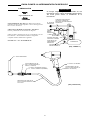
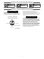
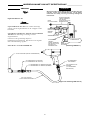
• Be sure all hoses and fittings are the correct size
and are tightly secured. See Dwg. TPD905--1 for a
typical piping arrangement.
• Always use clean, dry air at 90 psig 6.2 bar/620 kPa
maximum air pressure. Dust, corrosive fumes
and/or excessive moisture can ruin the motor of an
air tool.
• Do not lubricate tools with flammable or volatile
liquids such as kerosene, diesel or jet f uel.
• Do not remove any labels. Replace any damaged
label.
• The use of a hose whip is recommended. A coupler
connected directly to the air inlet increases tool bulk
and decreases to ol maneuv erability.
• For maximum performance, the coupler on the wall
should be the next size larger than the coupler used
on the tool. The coupler closest to the tool should
not be less than the proper air supply hose size.
USING THE TOOL
• Always wear eye protection when operating or
performing maintenance on this tool.
• Always wear hearing protection when operating
this tool.
• Keep hands, loose clothing, long hair and jewelry
away from working end of tool.
• Note the position o f the reversing lever before
operating the tool so as to be aware of the direction
of rotation when operating the throttle.
• Keep body stance balanced and firm. Do not
overreach when operating this tool. Anticipate and
be alert for sudden cha nges in motion, reaction
torques, or forces during start--up and operation.
• Tool shaft may continue to rotate briefly after
throttle is released.
• Air powered tools can vibrate in use. Vibration,
repetitive motions or uncomfortable positions may
be harmful to your hands and arms. Stop using any
tool if discomfort, tingling feeling or pain occurs.
Seek medical advice before resuming use.
• Use accessories recommended by Ingersoll--Rand.
• Use only impact sockets and accessories. Do not use
hand (chrome) sockets o r accessories.
• Impact Wrenches are not torque wrenches.
Connections requiring specific torque must be
checked with a torque meter after fitting with an
impact wrench.
• This tool is no t designed for working in explosive
atmospheres.
• This tool is not insulated against electric shock.
• Do not carry or drag the tool by the hose.
• Prevent exposure and breathing of harmful dust
and particles created by power tool use:
Some dust created by power sanding, sawing,
grinding, drilling and other construction
activities contains chemicals known to cause
cancer, birth defects or other reproductive
harm. Some examples of these chemicals are:
-- lead from lead based paints,
-- crystalline silica f rom bricks and cement
and other masonry products, and
-- arsenic and chromium from chemically
treated lumber.
Your risk from these exposures varies,
depending on how often you do this type of
work. To reduce your exposure to these
chemicals: work in a well ventilated area, and
work with approved safety equipment, such as
those dust masks that are specially designed to
filter out microscopic particles.
The use of other than genuine Ingersoll--Rand replacement parts may result in safety hazards, decreased tool
performance, and increased maintenance, and may invalidate all warranties.
Repairs should be made only by authorized trained personnel. Consult your nearest Ingersoll--Rand Authorized
Servicenter.
GB

2
WARNING SYMBOL IDENTIFICATION
Always wear eye protection
when operating or
performing maintenance
on this tool.
WARNING
WARNING
Always wear hearing
protection when operating
this tool.
Read this manual before
operating tool.
WARNING
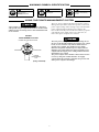
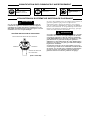
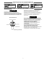
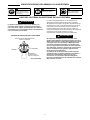
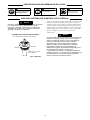
USING THE POWER MANAGEMENT SYSTEM
Air wrenches are not torque control devices. Fasteners
with specific torque requirements must be checked with
suitable torque measuring devices after installation with
an air wrench.
POWER
MANAGEMENT SYSTEM
(Dwg. TPD1339)
POWER SETTING INDICA TORS
MAXIMUMMINIMUM
POWER
MANAGEMENT
DIAL
The 2131 series of Impact Wrenches incorporate a Power
Management System that allows the operator to select four
power output settings. These settings range from minimum
power output through maximum power output in the
forward d irection on ly. The Air Wren ch will always operate
at maximum power output in the reverse direction, no
matter what power output level is selected.
The four power setting indicators of increasing size on
the rear of the housing indicate increasing power output
levels, are for reference only and DO NOT denote a
specific power output. The smallest power setting
indicator designates minimum power output, the two
middle power setting indicators denote medium power
outputs and the largest power setting indicator denotes
maximum power output.
The power output can be further reduced in forward or
reverse by using the variable throttle. Air supply
systems which do not deliver adequate air pressure can
affect power output at all settings.

3
PLACING TOOL IN SERVICE
LUBRICATION
Ingersoll--Rand No. 50
Ingersoll--Rand No. 115--1LB for routine external
lubrication of the impact mechanism through the Hammer
Case Grease Fitting.
Use Ingersoll--Rand No. 105--1LB or Ingersoll--Rand
105--8LB when disassembling and assembling the impact
mechanism.
Always use of an air line lubricator with these tools.
We recommend the following Filter--Lubricator--Regulator
Unit:
F o r U S A -- N o . C 1 8 -- 0 3 -- F K G 0 -- 2 8
Do not mark any nonmetallic surface on this tool with
customer identification codes. Such actions could affect
tool performance.
MAIN LINES 3 TIMES
AIR TOOL INLET SIZE
TO
AIR
SYSTEM
TO
AIR
TOOL
LUBRICATOR
REGULATOR
FILTER
BRANCH LINE 2 TIMES
AIR TOOL INLET SIZE
DRAIN REGULARLY
COMPRESSOR
(Dwg. TPD905--1)
(Dwg. TPD1674--2)
AIR SUPPLY (FROM COMPRESSOR)
3/8” COUPLER OR LARGER
(I--R PART NO. MSCF33)
I--R PART NO. MSPM32 (MALE)
I--R PART NO. MSPF32 (FEMALE)
3/8” COUPLER OR LARGER
(I--R PART NO. MSCF32)
I--R PART NO. MSPM32
3/8” AIR HOSE
WITH 1/4” NPT FITTINGS

4
PLACING TOOL IN SERVICE
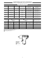
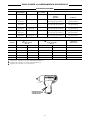
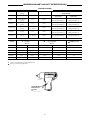
SPECIFICATIONS
Model Type of Handle Drive Impacts per min. Recommended
Torque Range
Forward
ft --lb (Nm)
Reverse
ft --lb (Nm)
2131A pistol grip 1/2” 1,250
50--400 [450 Max.]
(68 --542 [610 Max.] )
550 [600 Max.]
(746 [813 Max.] )
2131AS pistol grip 1/2” 1,250
50--400 [450 Max.]
(68 --542 [610 Max.] )
550 [600 Max.]
(746 [813 Max.] )
2131AS-- 2 pistol grip
1/2”
(2” ext.)
1,250
50--400 [450 Max.]
(68 --542 [610 Max.] )
550 [600 Max.]
(746 [813 Max.] )
2131QT pistol grip 1/2” 1,250
50--400 [450 Max.]
(68 --542 [610 Max.] )
550 [600 Max.]
(746 [813 Max.] )
2131QT-2 pistol grip
1/2”
(2” ext.)
1,250
50--400 [450 Max.]
(68 --542 [610 Max.] )
550 [600 Max.]
(746 [813 Max.] )
Model
H Impacting
Sound Level
dB (A)
z Free-Speed
Sound Level
dB (A)
D Vibration Level
Pressure Power Pressure Power m/s
2
2131A 96.8 106.8 93.6 103.6 5.7
2131AS 96.7 106.7 87.2 97.2 4.9
2131AS-2 96.7 106.7 87.2 97.2 4.9
2131QT 96.3 106.3 82.0 92.0 4.4
2131QT-2 96.3 106.3 82.0 92.0 4.4
H Tested in Accordance with PNUEROP PN8NTC1.2
z Tested in Accordance with CAGI/ANSI S12.41
D Tested in Accordance with IS03744
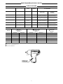
TPD1885
Letter/Number
Date Code
Location
A________
A________

Ingersoll- Rand, Co.
Swan Lane, Hindley Green, Nr. Wigan WN2 4EZ, U.K.
98/37/EC
November, 2001
ISO8662 PNEUROP PN8NTC1
(2001 → ) A01M XXXXX →
Model 2131 Series
November, 2001
5
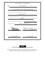
DECLARATION OF CONFORMITY
We
(supplier’s name)
(address)
declare under our sole responsibility that the product,
to which this declaration relates, is in compliance with the provisions of
Directives.
By using the following Principle Standards:
Serial No. Range:
D. Vose Patrick S. Livingston
Name and signature of authorised persons Name and signature of authorised persons
Date Date
SAVE THESE INSTRUCTIONS. DO NOT DESTROY.
When the life of the tool has expired, it is recommended that the tool be disassembled,
degreased and parts be separated by material so that they can be recycled.

Adressez toutes vos communications au Bureau
Ingersoll--Rand ou distributeur le plus proche.
Ingersoll--Rand Company 2001
Imprimé aux É.U.
04577649
Form P7486--EU
Révision 2
Novembre, 2001
MODE D’EMPLOI DES CLÉS À CHOCS AUTOMOBILES
SÉRIE EXTRA FORTE MODÈLES
2131A, 2131AS, 2131AS--2, 2131QT ET 2131QT--2
NOTE
Les clés à chocs Modèles 2131A, 2131AS, 2131AS--2, 2131QT et 2131QT--2 sont destinées aux
réparations automobiles générales, à l’entretien des pneus et aux applications de parc
automobile nécessitant des couples élevés.
Ingersoll--Rand ne peut être tenu responsable de la modification des outils par le client pour
les adapter à des applications qui n’ont pas été approuvées par Ingersoll--Rand.
ATTENTION
D’IMPORTANTES INFORMATIONS DE SÉCURITÉ SONT JOINTES.
LIRE CE MANUEL AVANT D’UTILISER L’OUTIL.
L’EMPLOYEUR EST TENU DE COMMUNIQUER LES INFORMATIONS
DE CE MANUEL AUX EMPLOYÉS UTILISANT CET OUTIL.
LE NON RESPECT DES AVERTISSEMENTS SUIVANTS PEUT CAUSER DES BLESSURES.
MISE EN SERVICE DE L’OUTIL
• Cet outil doit toujours être exploité, inspecté et
entretenu conformément à toutes les réglementations
(locales, départementales, fédérales et nationales),
applicables aux outils pneumatiques
tenus/commandés à la main.
• Pour la sécurité, les performances optimales et la
durabilité maximale des pièces, cet outil doit ê tre
connecté à une alimentation d’air comprimé de
6,2 bar (620 kPa) maximum à l’entrée.
• Couper toujours l’alimentation d’air comprimé et
débrancher le flexible d’alimentation avant
d’installer, déposer ou ajuster tout accessoire sur cet
outil, ou d’entreprendre une opération d’entretien
quelconque sur l’outil.
• Ne pas utiliser des flexibles ou des raccords
endommagés, effilochés ou détériorés.
• S’assurer que tous les flexibles et les raccords sont
correctement dimensionnés et bien serrés. Voir Plan
TPD905--1 pour un exemple type d’agencement des
tuyauteries.
• Utiliser toujours de l’air sec et propre à une pression
maximum de 6,2 bar. La poussière, les fumées
corrosives et/ou une humidité excessive peuvent
endommager le moteur d’un outil pneumatique.
• Ne jamais lubrifier les outils avec des liquides
inflammables ou volatiles tels que le kérosène, le gasol
ou le carburant d’aviation.
• Ne retirer aucune étiquette. Remplacer toute étiquette
endommagée.
• L’utilisation d’un flexible suspendu est recommandée.
Un raccord connecté directement au raccord
d’admission augmente le poids de l’outil et réduit
donc sa manoeuvrabilité.
• Pour obtenir les performances maximales, le raccord
mural doit être d’un diamètre immédiatement
supérieur à celui du raccord utilisé sur l’outil. Le
raccord le plus proche de l’outil ne doit pas être
inférieur au diamètre du flexible d’alimentation
correct.
UTILISATION DE L’OUTIL
• Porter toujours des lunettes de protection pendant
l’utilisation et l’entretien de cet outil.
• Porter toujours une protection acoustique pendant
l’utilisation de cet outil.
• Gardez les mains , vêtements amples, cheveux longs et
bijoux éloignés de l’extrémité rotative de l’outil.
• Noter la position du levier d’inversion avant de mettre
l’outil en marche de manière à savoir dans quel sens il
va tourner lorsque la commande est actionnée.
• Garder une position équilibrée et ferme. Ne pas se
pencher trop en avant pendant l’utilisation de cet
outil. Anticiper et prendre garde aux changements
soudains de mouvement, couples de réaction ou forces
lors du démarrage et de l’exploitation.
• La rotation des accessoires de l’outil peut continuer
pendant un certain temps après le relâchement de la
gâchette.
• Les outils pneumatiques peuvent vibrer pendant
l’exploitation. Les vibrations, les mouvements
répétitifs et les positions inconfortables peuvent
causerdesdouleursdanslesmainsetlesbras.
N’utiliser plus d’outils en cas d’inconfort, de
picotements ou de douleurs. Consulter un médecin
avant de recommencer à utiliser l’outil.
• Utiliser les accessoires recommandés par
Ingersoll-Rand.
• N’utiliser que les douilles et les accessoires pour clés à
chocs. Ne pas utiliser les douilles et accessoires
(chromés) de clés manuelles.
• Lesclésàchocsnesontpasdesappareils
dynamométriques. Les connexions nécessitant un
couple de serrage spécifique doivent être vérifiées
avec un mesureur de couple après avoir été
assemblées avec une clé à chocs.
• Cet outil n’est pas conçu pour fonctionner dans des
atmosphères explosives.
• Cet outil n’est pas isolé contre les chocs électriques.
• Ne transportez pas l’outil par son flexible d’air
comprimé.
• Evitez toute exposition et respiration des poussières et
particules nocives créées par l’emploi de l’outil
pneumatique:
Certaines poussières produites par les opérations
de ponçage, sciage, meulage, perçage e t autres
activités de construction contiennent des produits
chimiques qui sont reconnus comme pouvant
causer le cancer, des infirmités de naissance ou
d’autres risques à effets nocifs. Parmi ces
produits chimiques on trouve:
-- le plomb des peintures à base de plomb,
-- les cristaux de silice contenus dans les
briques, le ciment et d’autres produits de
maçonnerie, et
-- l’arsenic et le chrome des bois traités
chimiquement.
Le risque présenté par l’exposition à ces
poussières est fonction de la fréquence et du type
de travail effectué. Pour réduire l’exposition à ces
produits chimiques : travaillez dans une zone
bien aérée, et utilisez les équipements de sécurité
approuvés, tels que les masques à poussière qui
sont spécialement conçus pour filtrer et arrêter
les particules microscopiques.
NOTE
L’utilisation de rechanges autres que lespiècesd’origine Ingersoll--Randpeut causer desrisques d’insécurité, réduire les
performances de l’outil et augmenter l’entretien, et peut annuler toutes les garanties.
Les r éparations ne doivent être effectuées que par des r éparateurs qualifiés autorisés. Consultez votre Centre de Service
Ingersoll--Rand le plus proche.
F

7
SIGNIFICATION DES SYMBOLES D’AVERTISSEMENT
Porter toujours des lunettes
de protection pendant
l’utilisation et l’entretien de
cet outil.
ATTENTION ATTENTION
Porter toujours une
protection acoustique
pendant l’utilisation de cet
outil.
Lire ce manuel avant
d’utiliser l’outil.
ATTENTION
UTILISATION DU SYSTÈME DE GESTION DE PUISSANCE
ATTENTION
Les clés pneumatiques ne sont pas des dispositifs de
contrôle de couple. Les fixations ayant des exigences
spécifiques de couple doivent être contrôlées avec des
dispositifs dynamométriques appropriés après avoir été
assemblées avec une clé pneumatique.
SYSTÈME DE GESTION DE PUISSANCE
(Plan TPD1339)
MAXIMUMMINIMUM
INDICATEURS DE RÉGLAGE DE PUISSANCE
CADRAN DE GESTION
DE PUISSANCE
Le clés à choc s Modèle 2131 est équipées d’un système de
gestion de puissance qui permet à l’opérat eur de
sélec tionner quatre réglages de pui ssance. Ces réglages
vont de la puissance minimum à la puissance maximum e n
marche avant seulement. La cl é pneumatique fonctionnera
toujours à la puissance maximum en desserrage, quel que
soit le niveau de puissance séle ctionné.
ATTENTION
Les quatre indicateurs de réglage de puissance de taille
croissante sur l’arrière du corps indiquent les niveaux
croissants de puissance à titre de référence seulement,
et NE DÉNOTE PAS une puissance spécifique. Le plus
petit indicateur de puissance indique la puissance
minimum, les deux indicateurs du centre indiquent des
puissances moyennes, et le plus gros indicateur indique
la puissance maximum.
La puissance peut être encore plus réduite en serrage
ou desserrage à l’aide de la commande variable de mise
en marche. Les circuits d’air comprimé ne fournissant
pas une pression d’air adéquate peuvent affecter la
puissance fournie à toutes les positions de réglage.

8
MISE EN SERVICE DE L’OUTIL
LUBRIFI CATION
Ingersoll--Rand No. 50
Ingersoll--Rand No. 115--1LB pour une lubrification
extérieure normale du mécanisme de chocs par
l’intermédiaire du raccord de graissage du carter de
marteau.
Ingersoll--Rand No. 105--1LB ou Ingersoll--Rand
No. 105--8LB pour le démontage et l’assemblage du
mécanisme de chocs.
Utiliser toujours un lubrificateur avec ces outils. Nous
recommandons l’emploi du filtre--régulateur--lubrificateur
suivant:
É . U . -- N o . C 1 8 -- 0 3 -- F K G 0 -- 2 8
AVERTISSEMENT
Ne pas marquer les codes d’identification client sur les
surfaces non métalliques de cet outil. De telles actions
pourraient affecter les performances de l’outil.
TU
Y
A
UTERIE PRINCIP
A
LE
A
U
MOINS 3 FOIS LA DIMEN-
SION DE L’ADMISSION D’AIR
DE L’OUTIL
VERS LE
RÉSEAU D’AIR
COMPRIMÉ
VERS
L’OUTIL
PNEU-
MATIQUE
LUBRIFICATEUR
RÉGULATEUR
FILTRE
LIGNE SECONDAIRE AU
MOINS 2 FOIS LA DIMEN-
SION DE L’ADMISSION
D’AIR DE L’OUTIL
VIDANGER
RÉGULIÈREMENT
COMPRESSEUR
(Plan TPD905--1)
(Plan TPD1674--2)
ALIMENTATION D’AIR (DU COMPRESSEUR)
RACCORD 3/8” OU PLUS
(RÉF. I--R NO. MSCF33)
RÉF. I--R NO. MSPM32 (MÂLE)
RÉF. I--R NO. MSPF32 (FEMELLE)
RACCORD 3/8” OU PLUS
(RÉF. I--R NO. MSCF32)
RÉF. I--R NO. MSPM32
FLEXIBLE D’AIR COMPRIMÉ 3/8”
AVEC RACCORDS 1/4” NPT

9
MISE EN SERVICE DE L’OUTIL
SPÉCIFICATIONS
Modèle Type de Poignée Entraîne-
ment
Coups par
minute
Gamme de couples
recommandée
Marche avant
ft--lb (Nm)
Marche
arrière
ft--lb (Nm)
2131A poignée pistolet 1/2” 1.250 50/400” [450 max.]
(68/542” [610 max.] )
550 (600 max.)
(746 [813 max.] )
2131AS poignée pistolet 1/2” 1.250 50/400” [450 max.]
(68/542” [610 max.] )
550 (600 max.)
(746 [813 max.] )
2131AS--2 poignée pistolet 1/2”
2” ext.
1.250 50/400” [450 max.]
(68/542” [610 max.] )
550 (600 max.)
(746 [813 max.] )
2131QT poignée pistolet 1/2” 1.250 50/400” [450 max.]
(68/542” [610 max.] )
550 (600 max.)
(746 [813 max.] )
2131QT--2 poignée pistolet 1/2”
2” ext.
1.250 50/400” [450 max.]
(68/542” [610 max.] )
550 (600 max.)
(746 [813 max.] )
Modèle
H Chocs
Niveau de son
dB (A)
z Vitesse à vide
Niveau de son
dB (A)
D Niveau de
vibration
Pression Puissance Pression Puissance m/s
2
2131A 96,8 106,8 93,6 103,6 5,7
2131AS 96,7 106,7 87,2 97,2 4,9
2131AS-2 96,7 106,7 87,2 97,2 4,9
2131QT 96,3 106,3 82,0 92,0 4,4
2131QT-2 96,3 106,3 82,0 92,0 4,4
H Test selon PNUEROP PN8NTC1.2
z Test selon CAGI/ANSI S12.41
D Test selon IS03744
TPD1885
Position du
Code Date
à Lettre/Chiffre
A________

Ingersoll-Rand, Co.
ISO8662 PNEUROP PN8NTC1
Novembre, 2001
Modèles 2131
Swan L ane, Hindley Green, Nr Wigan WN2 4EZ, U.K.
98/37/CE
Novembre, 2001
(2001 → ) A01M XXXXX →
10
CERTIFICAT DE CONFORMITÉ
Nous
(nom du fournisseur)
(adresse)
déclarons sous notre seule responsabilité que le produit:
objet de ce certificat, est conforme aux prescriptions des Directives:
en observant les normes de principe suivantes:
N
o
.Serie:
D. Vose Patrick S. Livingston
Nom et signature des chargés de pouvoir Nom et signature des chargés de pouvoir
Date Date
NOTE
CONSERVEZ SOIGNEUSEMENT CES INSTRUCTIONS. NE PAS LES DÉTRUIRE.
A la fin de sa durée de vie, il est recommandé de démonter l’outil, de dégraisser les pièces et de les séparer en
fonction des matériaux de manière à ce que ces derniers puissent être recyclés.

Wenden Sie sich bei Rückfragen an Ihre nächste Ingersoll--Rand--
Niederlassung oder den autorisierten Fachhandel
Ingersoll--Rand Company 2001
Printed in Japan
04577649
Form--Nr. P7486--EU
Ausgabe 2
November, 2001
BEDIENUNGSANLEITUNG FÜR HOCHLEISTUNGS-- SCHLAGSCHRAUBER,
MODELLE 2131A, 2131AS, 2131AS--2, 2131QT UND 2131QT--2
HINWEIS
Schlagschrauber der Baureihe 2131 werden eingesetzt für allgemeine Fahrzeugreparaturen,
beim Rad-- und Reifenwechsel und für vielfältige Wartungstätigkeiten.
Ingersoll--Rand lehnt jede Haftung für Veränderungen an Werkzeugen ab, die ohne vorherige
Rücksprache mit Ingersoll--Rand vorgenommen werden.
ACHTUNG
NACHFOLGEND WICHTIGE SICHERHEITSHINWEISE.
DIESES HANDBUCH VOR INBETRIEBNAHME DES WERKZEUGES UNBEDINGT LESEN.
DER ARBEITGEBER IST VERPFLICHTET, DIE IN DIESEM HANDBUCH GEGEBENEN
INFORMATIONEN DEM BEDIENER ZUGÄNGLICH ZU MACHEN.
DIE NICHTEINHALTUNG DIESER WARNHINWEISE KANN ZU VERLETZUNGEN FÜHREN.
INBETRIEBNAHME DES WERKZEUGES
• Das Werkzeug stets nach den örtlich und landesweit
geltenden Vorschriften für
handgehaltene/ha ndbetriebene Druckluftwerkzeuge
betreiben.
• Zur E rzielung höchster Sicherheit, Leistung und
Haltbarkeit der Teile sollte dieses Werkzeug mit einem
maximalen Luftdruck von 6,2 bar/620 kPa (90 psig)
am Lufteinlaß.
• Vor Montage, Demontage oder Verstellung von
Aufsetzteilen bzw. Wartungsarbeiten die
Druckluftversorgung allseitig abschalten und
Druckluftschlauch abschließen.
• Keine beschädigten, durchgescheuerten oder
abgenutzten Luftschläuche und Anschlüsse
verwenden.
• Darauf achten, daß alle Schlä u che und Anschlüsse die
passende Größe haben und korrekt befestigt sind. In
Zeichnung TPD905--1 ist eine typische
Rohrleitungsanordnung abgebildet.
• Stets saubere, trockene Luft verwenden und einen
Luftdruck 6.2 bar/620 kPa (90 psig) verwenden.
Staub, ätzende Dämpfe und/o d er Feuchtigkeit können
den Motor eines Druckluftwerkzeug es beschädigen.
• Die Werkzeuge nicht mit brennbaren oder flüchtigen
Flüssigkeiten wie Kerosin und Diesel schmieren.
• Keine Schilder entfernen. Beschädigte Schilder
austauschen.
• Der E insatz eines Hahnschlauches wird empfohlen.
Wird direkt am Lufteinlaß eine Kupplung
angeschlossen, so vergrößert dies die Werkzeugmasse
und das Werkzeug läßt sich weniger leicht handhaben.
• Um maximale Leistung zu g ewährleisten, muß die
Kupplung an der Wand gegenüber der am Werkzeug
eingesetzten Kupplung um eine Stufe größer sein. Die
dem Werkzeug am nächsten gelegene Kupplung da rf
nicht kleiner sein als der verwendete
Luftzufuhrschlauch.
WERKZEUGEINSATZ
• Beim Betreiben oder Warten dieses Werkzeuges stets
Augenschutz tragen.
• Beim Betreiben dieses Werkzeuges stets Gehörschutz
tragen.
• Hände, lose Bekleidungsstücke, lange Haare und
Schmuckstücke vom beweglichen E nde des
Werkzeuges fernhalten.
• Vor der Inbetriebnahme auf die Position des
Umsteuerhebels achten, damit bei Betätigen der
Drossel die Drehrichtung schon bekannt ist.
• Auf sichere Körperhaltung achten. Während der
Benutzung des Werkzeuges nicht zu weit nach vorne
lehnen. Bei Anlauf und Betrieb auf Rückschlag achten
und auf plötzliche Änderungen der
Reaktionsdrehmomente und Gegenkräfte vorbereitet
sein.
• Nach dem Loslassen des Drückers kann die Welle des
Werkzeugs noch kurz weiterdrehen.
• Druckluftbetriebene Werkzeuge können wä h rend des
Betriebs vibrieren. Vibrationen, häufige gleichförmige
Bewegungen oder unbequeme Po sitionen können
schädlich für Hände und Arme sein. Bei Unbehagen,
Kribbeln oder Schmerzen das Werkzeug nicht mehr
benutzen. Vor dem erneuten Arbeiten mit dem
Werkzeug ärztliche Hilfe aufsuchen.
• Stets von Ingersoll--Rand empfohlenes Zubehö r
verwenden.
• Nur Schlagschrauber--Steckschlüssel und --Zubehör
verwenden. Keine Hand--Steckschlüssel (Chrom) oder
--Zubehör verwenden.
• Schlagschrauber sind keine Drehmomentschrauber.
Verbindungen, die ein bestimmtes Drehmoment
erfordern, müssen nach dem Anziehen mit dem
Schlagschrauber mit Hilfe eines
Drehmomentmessgerätes überprüft werden.
• Das Werkzeug ist nicht für die Arbeit in explosiven
Atmosphären geeignet.
• Dieses Werkzeug ist nicht gegen elektrischen Schlag
isoliert.
• Das Werkzeug nicht am Schlauch tragen oder ziehen.
• Vermeiden Sie, sich den Schadstoffen auszusetzen und
die Schadstoffe einzuatmen, die bei Verwendung von
Elektro-- und Druckluftwerkzeugen freigesetzt
werden:
Bei der Nutzung von Maschinen zum Schleifen,
Sägen, Trennschleifen, Bohren und weiteren
Tätigkeiten auf dem Bausektor entstehen Stäube,
die ihrerseits Chemikalien enthalten, die
bekanntermaßen Krebs, Schädigungen der
Nachkommen oder andere Schädigungen des
menschlichen Reproduktionssystems
verursachen. Zu Beispielen für diese Chemikalien
zählen:
-- Blei, freigesetzt aus bleihaltigen
Anstrichstoffen,
-- Kristallines Silikat, a bgegeben von Ziegeln
und Zement sowie weiteren Baustoffen und
-- Arsen und Chrom, freigesetzt aus chemisch
behandelten Hölzern.
Die durch solche Aussetzungen bedingten Risiken
für die Gesundheit unterscheiden sich je nach d er
Häufigkeit, mit der solche Tätigkeiten
durchgeführt werden. Um die Aussetzung zu
diesen chemischen Stoffen herabzusetzen, s ind
folgende Maßnahmen zu ergreifen: Alle Arbeiten
sind in gut belüfteten Bereichen durchzuführen
und bei allen Arbeiten sind zugelassene
persönliche Schutzausrüstungen zu tragen.
Hierzu gehören b eispielsweise
Atemschutzmasken, die spezifisch auf da s
Herausfiltern mikroskopisch kleiner Partikel
ausgelegt sind.
HINWEIS
Die Verwendung von nicht Original--Ingersoll--Rand--Ersatzteilen kann Sicherheitsrisiken, verringerte Standzeit und erhöhten
Wartungsbeda rf nach sich ziehen und alle Garantieleistungen ungültig machen.
Reparaturen sollen nur von geschultem Personal durchgeführt werden. Wenden Sie sich an Ihre nächste Ingersoll--Rand--
Niederlassung oder den autorisierten Fachhandel.
D

12
IDENTIFIKATION VON WARNSYMBOLEN
ACHTUNG ACHTUNG
Dieses handbuch vor
inbetriebnahme des
werkzeuges unbedingt lesen.
ACHTUNG
Beim Betreiben oder Warten
dieses Werkzeuges stets
Augenschutz tragen.
Beim Betreiben dieses
Werkzeuges stets
Gehörschutz tragen.
VER WENDUNG DES LEISTUNGSREGLERS
ACHTUNG
Druckluftbetriebene Schrauber sind keine
Drehmomentwerkzeuge. Verbindungen, die ein
bestimmtes Drehmoment erfordern, müssen nach dem
Anziehen mit dem Druckluftschrauber mit Hilfe eines
geeigneten Drehmomentmeßgerätes überprüft werden.
LEISTUNGSREGLER
LEISTUNGSANZEIGEN
MINIMUM
MAXIMUM
DREHREGLER
(Zeichnung TPD1339)
Schlagschrauber der Baureihe 2131 sind mit einem
Leistungsregler ausgerüstet, über den der Bediener vier
Stufen der Abgabeleistung einstellen kann. Die
Einstellungen reichen von minimaler bis zu maximaler
Leistungsabgabe in Vorwärtsrichtung. Druckluftbetriebene
Schrauber arbeiten in Rückwärtsrichtung immer mit
maximaler Leistungsabgabe, unabhängig von der
Reglerstellung.
ACHTUNG
Die vier Leistungsanzeigen auf der Gehäuserückseite
sind unterschiedlich groß und zeigen in aufsteigender
Reihenfolge die Stufen vermehrter Leistungsabgabe an.
Sie dienen nur für Bezugszwecke und zeigen KEIN
spezifisches Abgabeniveau an. Die kleinste
Leistungsanzeige verweist auf minimale
Leistungsabgabe; die beiden mittleren auf mittlere
Leistungsabgabe, die größte auf maximale
Leistungsabgabe.
Die vom Werkzeug abgegebene Leistung kann in
Vorwärts-- und Rückwärtsrichtung über die
Drückerstellung weiter verringert werden.
Druckluftsysteme, die Luft bei unzureichendem Druck
bereitstellen, können einen Einfluß auf die
Leistungsabgabe bei allen Einstellpositionen haben.

13
INBETRIEBNAHME DES WERKZEUGS
SCHMIERUNG
Ingersoll--Rand Nr. 50
Zur routinemäßigen, externen Schmierung des Schlagwerks
(über den Hammergehäuse--Schmiernippel) Ingersoll--Rand
Öl Nr. 115--1LB verwenden.
Bei Zerlegung und Zusammenbau des Schlagwerks
Ingersoll--Rand Öl Nr. 105 --1LB oder Ingersoll--Rand Öl
Nr. 105--8LB verwenden.
Das Werkzeug stets mit einem Leitungsöler verwenden. Es
wird folgende Filter--Regler --Öler--Kombination e mpfohlen:
Für die USA: Nr. C18--0 3--FKG0--28
VORSICHT
Auf der nicht metallischen Oberfläche des Werkzeugs
dürfen keine kundenseitigen Identifizierungscodes
angebracht werden. Hierdurch könnte die Leistung des
Werkzeugs beeinträchtigt werden.
HAUPTROHRLEITUNG MIT DREIFACHEM
DURCHMESSER DES
LUFTEINLASSES
ZUM
DRUCKLUFT-
SYSTEM
ZUM
DRUCKLUFT-
WERKZEUG
ÖLER
REGLER
FILTER
ZWEIGLEITUNG, 2--MAL
DURCHMESSER DES
WERKZEUGEINLASSES
REGELMÄSSIG
ABLASSEN
KOMPRESSOR
(Zeichn. TPD905--1)
(Dwg. TPD1674--2)
3/8” DRUCKLUFTSCHLAUCH
MIT 1/4” NPT --ANSCHLÜSSEN
DRUCKLUFTVERSORGUNG
(VOM KOMPRESSOR)
3/8” KUPPLER ODER GRÖSSER
(I--R TEILE--NR. MSCF33)
I--R TEILE--NR. MSPM32 (STECKTEIL)
I--R TEILE--NR. MSPF32 (AUFNAHME)
I--R TEILE--NR. MSPM32
3/8” KUPPLUNG ODER
GRÖSSER
(I--R TEILE--NR. MSCF32)

14
INBETRIEBNAHME DES WERKZEUGS
TECHNISCHE DATEN
Modell Griffart Antrieb Schläge/Minute Empfohlenes Arbeitsdrehmoment
Vorwärts
ft --lb (Nm)
Rückwärts
ft --lb (Nm)
2131A Pistolengriff 1/2” 1,250
50--400 [450 Max.]
(68 --542 [610 Max.] )
550 [600 Max.]
(746 [813 Max.] )
2131AS Pistolengriff 1/2” 1,250
50--400 [450 Max.]
(68 --542 [610 Max.] )
550 [600 Max.]
(746 [813 Max.] )
2131AS-- 2 Pistolengriff
1/2”
(2” Verl.)
1,250
50--400 [450 Max.]
(68 --542 [610 Max.] )
550 [600 Max.]
(746 [813 Max.] )
2131QT Pistolengriff 1/2” 1,250
50--400 [450 Max.]
(68 --542 [610 Max.] )
550 [600 Max.]
(746 [813 Max.] )
2131QT-2 Pistolengriff
1/2”
(2” Verl.)
1,250
50--400 [450 Max.]
(68 --542 [610 Max.] )
550 [600 Max.]
(746 [813 Max.] )
Modell
H Schlagend
Schallpegel
dB (A)
z Frei drehend
Schallpegel
dB (A)
D Vibrationspegel
Druck Stärke Druck Stärke m/s
2
2131A 96,8 106,8 93,6 103,6 5,7
2131AS 96,7 106,7 87,2 97,2 4,9
2131AS-2 96,7 106,7 87,2 97,2 4,9
2131QT 96,3 106,3 82,0 92,0 4,4
2131QT-2 96,3 106,3 82,0 92,0 4,4
H Geprüft g emäß PNEUROP PN8NTC1.2
z Geprüft gemäß CAGI/ANSI S12.41
D Geprüft gemäß IS03744
TPD1885
Buchstabe/
Nummer
Datumscode
Ort
A________
A________

Ingersoll- Rand, Co.
Swan Lane, Hindley Green, Nr. Wigan WN2 4EZ, U.K.
ISO8662 PNEUROP PN8NTC1
November, 2001
(2001 → ) A01M XXXXX →
Baueihe 2131
98/37/EG
November, 2001
15
KONFORMITÄTSERKLÄRUNG
Wir
(Name des Herstellers)
(Adresse)
erklären hiermit, gemäß unserer alleinigen Verantwortung, daß die Geräte:
auf die sich diese Erklärung bezieht, den Richtlinien:
unter Anlehnung an die folgenden Grundnormen
entsprechen:
Serien--Nr.--Bereich:
D. Vose Patrick S. Livingston
Name und Unterschrift der Bevollmächtigten Name und Unterschrift der Bevollmächtigten
Datum Datum
HINWEIS
DIESE ANWEISUNGEN SIND SORGFÄLTIG AUFZUBEWAHREN. NICHT ZERSTÖREN.
Zur Entsorgung ist das Werkzeug vollständig zu demontieren, zu entfetten und nach Materialarten
getrennt der Wiederverwertung zuzuführen.

Indirizzare tutte le co municazioni al più vicino
concessionario od ufficio Ingersoll--Rand.
Ingersoll--Rand Company 2001
Stampato in U.S.A.
04577649
Modulo P7486--EU
Edizione 2
Novembre, 2001
ISTRUZIONI PER
CHIAVI AD I MPULSI ULTRA DUTY PER AUTOMEZZI MODELLI
2131A, 2131AS, 2131AS--2, 2131QT E 2131QT–2
AVVISO
Le chiavi ad impulsi serie 2131 sono state progettate per l’uso in attività generiche di
riparazione degli autoveicoli, manutenzione degli pneumatici ed applicazioni con macchine per
lavori pesanti.
La Ingersoll--Rand non è responsabile delle modifiche apportate alle pompe dai clienti per
adattarli ad applicazioni per le quali la Ingersoll--Rand non sia stata interpellata.
AVVERTENZA
IMPORTANTE INFORMAZIONE DI SICUREZZA ACCLUSA.
LEGGERE IL PRESENTE MANUALE PRIMA DI USARE L’ATTREZZO.
E’ RESPONSABILITÀ DEL DATORE DI LAVORO DI METTERE QUEST’INFORMAZIONE
NELLE MANI DELL’OPERATORE.
LA MANCATA OSSERVANZA DELLE SEGUENTI AVVERTENZE PUÒ CAUSARE LESIONI FISICHE
MESSA IN SERVIZIO DELL’ATTREZZO
• Usare, ispezionare e mantenere sempre quest’attrezzo
secondo tutti i regolamenti (locali, statali, federali e
nazionali), che po ssano essere applicabili agli a ttrezzi
a mano pneumatici.
• Per sicurezza, ma ssime prestazioni e massima
durabilità delle parti, usare quest’attrezzo ad una
massima pressione d’aria di 90 psig
(6,2 bar/620 kPa) all’ingresso con un flessibile di
alimentazione.
• Disinserire sempre l’alimentazione aria e staccare il
relativo tubo dall’attrezzo, prima di installare, togliere
o regolare qualsia si accessorio, oppure prima di
eseguire qualsiasi operazione di manutenzione
dell’attrezzo.
• Non adoperare tubi e raccordi danneggiati, consunti o
deteriorati.
• Assicurarsi che tutti i tubi ed i raccordi siano delle
corrette dimensioni e saldamente serrati. Consultare il
disegno TPD905--1 per una tipica disposizione dei
tubi.
• Usare sempre aria pulita ed asciutta alla pressione
max di 90 psig (6,2 bar/620 kPa) Polvere, fumi
corrosivi e/o un eccesso di umidità possono rovinare il
motore di un attrezzo pneumatico.
• Non lubrificare gli utensili con liquidi infiammabili o
volatili come kerosene, gasolio o combustibile per
aviogetti.
• Non togliere nessuna etichetta. Sostituire eventuali
etichette danneggiate.
• Si consiglia l’uso di un flessibile. Un raccordo
collegato direttamente all’ingresso dell’aria aumenta il
volume dell’attrezzo e ne diminuisce la manov rabilità.
• Per prestazioni ottimali, il racco rdo a muro deve avere
una dimensione leggermente maggiore rispetto a
quella del raccordo sull’attrezzo. Il raccordo più
vicino all’attrezzo non deve avere un diametro
inferiore alla corretta dimensione del flessibile di
alimentazione dell’aria.
COME USARE L’ATTREZZO
• Indossare sempre degli occhiali protettivi quando si
adopera questo attrezzo o se ne esegue la
manutenzione.
• Indossare sempre delle cuffie protettive quando si
adopera questo attrezzo.
• Tenere le mani, vestiti larghi, capelli lunghi e
gioielleria fuori dalla portata del lato in funzione
dell’utensile.
• Verificare la posizione della leva di reversibilità prima
di azionare l’attrezzo in modo da essere consci della
direzione di rotazione quando si aziona l’utensile.
• Mantenere con il corpo una posizione salda e ben
bilanciata. Non sbilanciarsi durante l’uso di questo
utensile. Fare attenzione e cercare di anticipare
improvvise variazioni di movimento, coppie di
reazione, o forze inaspettate durante l’avviamento e
l’uso di qualsiasi utensile.
• Gli attrezzi pneumatici possono vibrare durante l’uso.
Le vibrazioni, i movimenti ripetitivi o le posizioni
scomode possono risultare dannosi per le mani e le
braccia. Interrompere l’uso dell’utensile se si
avvertono sintomi di disagio fisico, formicolio o
dolore. Interpellare un medico prima di riprendere il
lavoro.
• Usare accessori raccomandati da lla Ingersoll--Rand.
• Usare solo boccole ed accessori ad impulso. Non usare
boccole a ma n o (cromate) o accessori.
• Questo utensile non è stato progettato per operare in
atmosfere esplosive.
• Le chiavi ad impulsi non sono chiavi torsiometriche.
Collegamenti che richiedono coppie specifiche devono
essere controllati con un torsiometro dopo
l’installazione con una chiave ad impulsi.
• Questo utensile non è isolato contro le scosse
elettriche.
• Non trasportare o trascinare l’attrezzo tenendolo per
il tubo.
• Prevenire l’esposizione e la respirazione d i polvere e
particelle pericolose dovute all’uso si s tumenti
elettrici:
La polvere causata da smerigliatura, segatura,
macinatura, trapanatura e altre attività relative
alla costruzione contiene sostanze chimiche note
come cause di cancro, di menoma zioni alla nascita
o di altri danni legati alla riproduzione. Tali
sostanze chimiche sono, ad esempio:
-- vernici a ba se di piombo,
-- silice cristallina derivante da mattoni e
cemento e altri prodotti per muratura,
-- arsenico e cromo derivanti da legname
trattato chimicamente.
I rischi causati dalle esposizioni variano in ba se
alla frequenza con cui viene eseguito questo tipo
di lavori. Per ridurre l’esposizione a tali sostanze
chimiche: lavorare in una zona ben ventilata, con
attrezzature di sicurezza approvate come le
maschere per protezione dalla polvere progettate
specificamente per eliminare con il filtro le
particelle microscopiche.
AVVISO
L’uso di ricambi non originali Ingersoll--Rand potrebbe causare condizioni di pericolosità, compromettere le prestazioni
dell’attrezzo ed aumentare la necessità di manutenzione, inoltre potrebbe invalida re tutte le garanzie.
Le riparazioni devono essere effettuate soltanto da personale autorizzato e qualificato. Rivolgersi al più vicino centro di
assistenza tecnica Ingersoll--Rand.
I

17
IDENTIFICAZIONE DEI SIMBOLI DI AVVERTENZA
AVVERTENZA
AVVERTENZA
Leggere il presente manuale
prima di usare l’attrezzo.
AVVERTENZA
Indossare sempre degli occhiali
protettivi quando si adopera
questo attrezzo o se ne esegue
la manutenzione.
Indossare sempre delle
cuffie protettive quando si
adopera questo attrezzo.
USO DEL SISTEMA DI GESTIONE DELLA POTENZA
AVVERTENZA
Le chiavi pneumatiche non sono attrezzi con
controllo della coppia. I dispositivi d i fissaggio
che richiedono coppie specifiche d evono essere
controllati con un torsiometro dopo l’installazione
con una chiave pneumatica.
SISTEMA DI GESTIONE DELLA POTENZA
INDICATORI DI IMPOSTAZIONE
DELLA POTENZA
MINIMO
MASSIMO
(Fig. TPD1339)
MANOPOLA
DI GESTIONE
DELLA POTENZA
Le chiavi ad impulsi serie 2131 incorporano un
Sistema di gestione della potenza che consente
all’operatore di scegliere tra quattro impostazioni per
la potenza di uscita. Queste impostazioni vanno da
una potenza di uscita minima ad una potenza di
uscita massima solo nella direzione in avanti. Le
chiavi pneumatiche funzionano sempre alla massima
potenza di uscita nella direzione inversa,
prescindendo dal livello di potenza selezionato.
AVVERTENZA
Gli indicatori di dimensione crescente delle
quattro impostazioni di potenza segnati sul retro
della sede indicano i livelli della potenza di uscita
e fungono solo da riferimento e NON denotano
un’uscita di potenza specifica. L’indicatore più
piccolo rappresenta la potenza di uscita minima, i
due indicatori centrali le potenze di uscita media,
mentre l’indicatore più grande rappresenta la
potenza di uscita massima.
La potenza di uscita può essere ulteriormente
ridotta in avanti o indietro mediante il grillett o. I
sistemi di alimentazione dell’aria che non
forniscono una pressione dell’aria adeguata
possono influenzare tutte le impostazioni relative
alla potenza di uscita.

18
MESSA IN SERVIZIO DELL’UTENSILE
LUBRIFICAZIONE
Ingersoll--Rand Nr. 50
Ingersoll--Rand Nr. 115--1LB per lubrificazione esterna di
routine del meccanismo ad impulsi attraverso l’ingrassatore
posto sulla cassa del martello.
Usare Ingersoll--Rand Nr. 105--1LB o Ingersoll--Rand
105--8LB per lo smontaggio e il montaggio del meccanismo
ad impulsi.
Con questi attrezzi usare sempre un lubrificatore di lineaSi
raccomanda l’uso del seguente gruppo
filtro--regolatore--lub r ificatore:
Per gli USA -- Nr. C18--03--FKG0--28
ATTENZIONE
Non contrassegnare alcuna superficie non metallica su
questo attrezzo con i codici di identificazione del cliente.
Ciò potrebbe compromettere le prestazioni
dell’attrezzo.
CONDOTTO PRINCI-
PALE 3 VOLTE LA DI-
MENSIONE DEL RAC-
CORDO DELLO STRU-
MENTO
AL SISTEMA AD
ARIA
COMPRESSA
ALLO STRU-
MENTO AD
ARIA COM-
PRESSA
LUBRIFICATORE
REGOLATORE
FILTRO
CONDOTTO SECOND-
ARIO 2 VOLTE LA DI-
MENSIONE DEL RAC-
CORDO DELLO STRU-
MENTO
SCARICARE
REGOLARMENTE
COMPRESSORE
(il disegno TPD905--1)
(per la figura TPD1674--2)
ALIMENTAZIONE ARIA (DAL COMPRESSORE)
RACCORDO DI 3/8” O MAGGIORE
(N. PARTE I--R MSCF33)
N. PARTE I--R MSPM32 (MASCHIO)
N. PARTE I--R MSPF32 (FEMMINA) I
N. P AR TE I--R MSPM32
RACCORDO DI 3/8”
O MAGGIORE
(N. PARTE I--R MSCF32)
TUBO DELL’ARIA DI 3/8”
CON RACCORDI NPT DI 1/4”

19
MESSA IN SERVIZIO DELL’UTENSILE
SPECIFICHE
Modello
Tipo
d’impugnatura
Attacco Impulsi/min. Gamma di coppie consigliata
In avanti
ft--lb (Nm)
Indietro
ft--lb (Nm)
2131A
impugnatura a
pistola
1/2”
1.250
50--400 [450 Max.]
(68 --542 [610 Max.] )
550 [600 Max.]
(746 [813 Max.] )
2131AS
impugnatura a
pistola
1/2”
1.250
50--400 [450 Max.]
(68 --542 [610 Max.] )
550 [600 Max.]
(746 [813 Max.] )
2131AS-- 2
impugnatura a
pistola
1/2”
(2” est.)
1.250
50--400 [450 Max.]
(68 --542 [610 Max.] )
550 [600 Max.]
(746 [813 Max.] )
2131QT
impugnatura a
pistola
1/2”
1.250
50--400 [450 Max.]
(68 --542 [610 Max.] )
550 [600 Max.]
(746 [813 Max.] )
2131QT–2
impugnatura a
pistola
1/2”
(2” est.)
1.250
50--400 [450 Max.]
(68 --542 [610 Max.] )
550 [600 Max.]
(746 [813 Max.] )
Modello
H Livello pressione
sonora ad impulsi
dB (A)
z Livello pressione
sonora a velocità libera
dB (A)
D Livello
di vibrazione
Pressione Potenza Pressione Potenza m/s
2
2131A 96,8 106,8 93,6 103,6 5,7
2131AS 96,7 106,7 87,2 97,2 4,9
2131AS2 96,7 106,7 87,2 97,2 4,9
2131QT 96,3 106,3 82,0 92,0 4,4
2131QT–2 96,3 106,3 82,0 92,0 4,4
H Testato in conformità c on P NUEROP PN8NTC1.2
z Testato in conformità con CAGI/ANSI S12.41
D Testato in conformità con S03744
TPD1885
A________
Lettera/Numero
Data
Ubicazione
A________

Ingersoll- Rand, Co.
Swan Lane, Hindley Green, Nr. Wigan WN2 4EZ, U.K.
ISO8662 PNEUROP PN8NTC1
Novembre, 2001
(2001 → ) A01M XXXXX →
Modelli 2131
98/37/CE
Novembre, 2001
20
DICHIARAZIONE DI CONFORMITÀ
Noi
(nome del fornitore)
(indirizzo)
dichiariamo sotto la nostra unica responsabilità che il prodotto:
a cui si riferisce l a presente dichiarazione è conforme alle normative delle direttive:
secondo i seguenti standard:
Numeri di Serie:
D. Vose Patrick S. Livingston
Nome e firma delle persone autorizzate Nome e firma delle persone autorizzate
Data Date
AVVISO
CONSERVARE QUESTE INSTRUZIONI. NON DISTRUGGERLE.
Quando l’attrezzo diventat o inutilizzabile, si raccomanda di smontarlo, sgrassarlo e separare i componenti secondo i
materiali in modo da poterli riciclare.
Seite wird geladen ...
Seite wird geladen ...
Seite wird geladen ...
Seite wird geladen ...
Seite wird geladen ...
Seite wird geladen ...
Seite wird geladen ...
Seite wird geladen ...
Seite wird geladen ...
Seite wird geladen ...
Seite wird geladen ...
Seite wird geladen ...
-
 1
1
-
 2
2
-
 3
3
-
 4
4
-
 5
5
-
 6
6
-
 7
7
-
 8
8
-
 9
9
-
 10
10
-
 11
11
-
 12
12
-
 13
13
-
 14
14
-
 15
15
-
 16
16
-
 17
17
-
 18
18
-
 19
19
-
 20
20
-
 21
21
-
 22
22
-
 23
23
-
 24
24
-
 25
25
-
 26
26
-
 27
27
-
 28
28
-
 29
29
-
 30
30
-
 31
31
-
 32
32


Ingersoll-Rand 2131A Instructions Manual
- Kategorie
- Schlagschrauber
- Typ
- Instructions Manual
in anderen Sprachen
- English: Ingersoll-Rand 2131A
- français: Ingersoll-Rand 2131A
- español: Ingersoll-Rand 2131A
- italiano: Ingersoll-Rand 2131A
- Nederlands: Ingersoll-Rand 2131A
Verwandte Artikel
-
Ingersoll-Rand 2131FRC-2 Instructions Manual
-
Ingersoll-Rand 40PSQ1 Operation and Maintenance Manual
-
-
-
-
-
-
-
-
Andere Dokumente
-
Facom NS.1400F Benutzerhandbuch
-
Ingersoll Rand 261 Benutzerhandbuch
-
GYS PNEUMATIC WINDSCREEN-SEAL CUTTING TOOL Bedienungsanleitung
-
-
-
-
-