Parkside PBS 2 A1 Translation Of The Original Instructions
- Kategorie
- Spielzeuge
- Typ
- Translation Of The Original Instructions

PETROL GRASS TRIMMER PBS 2 A1
BENZIN-SENSE
Originalbetriebsanleitung
PETROL GRASS TRIMMER
Translation of the original instructions
IAN 309505

Before reading, unfold the page containing the illustrations and familiarise yourself with all functions
of the device.
Klappen Sie vor dem Lesen die Seite mit den Abbildungen aus und machen Sie sich anschließend mit
allen Funktionen des Gerätes vertraut.
IE / NI Translation of the original instructions Page 5
DE / AT / CH Originalbetriebsanleitung Seite 27

A
B
1 2 3
4
5
6
7
7
12
13
23
24
25
30
31
14
15
16
17
18
19
17
20
21
22
8
9
28
29
59
60
2627
11
10

D
C
E
G
H
F
11
10
25
15
16
38
39
38
40
40
367
34
55
56
35 8
33
8 12
20 21
8
22
3 4
32
37
9
26
27
37
9

5
NI
IE
Sharpening the Thread Cutter .......... 20
Changing the Fuel Filter ................. 20
Winding up the spool .................. 20
Lubricating the gears ...................... 20
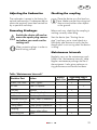
Adjusting the Carburettor ................ 21
Removing blockages ...................... 21
Checking the coupling ................... 21
Maintenance Intervals .................... 21
Storage ......................................22
General Storage Instructions ........... 22
Storage During Working Breaks ....... 22
Transport ................................... 22
Disposal / Environmental
Protection ..................................22
Spare Parts/Accessories ............. 23
Guarantee .................................24
Repair Service ............................25
Service-Center ............................25
Importer .................................... 25
Troubleshooting .........................26
Introduction
Congratulations on the purchase of your
new device. With it, you have chosen a
high quality product. During production,
this equipment has been checked for qual-
functionality of your equipment is therefore
guaranteed.
The operating instructions constitute
part of this product. They contain
important information on safety, use
and disposal.
Before using the product, familiarise
yourself with all of the operating
Content
Introduction .................................5
Intended Use ................................6
General Description ......................6
Delivery Contents ............................ 6
Functional Description ...................... 6
Summary ........................................ 6
Safety Functions ............................. 7
................ 8
Safety Information ....................... 8
Symbols in the Instructions ................ 8
Symbols on the Equipment ................ 8
General Safety Information ............... 9
Additional Safety Regulations .......... 11
Protective measures
against kickbacks .......................... 12
Assembly ...................................13
Installing the protective cover .......... 13
Fitting the Two-Part Tube ................. 13
Mounting the
multi-functional handlebar ............... 13
Initial Operation .........................13
Filling with Fuel ............................. 14
Putting on the shoulder strap ........... 14
Starting the Engine ........................ 15
Operation ..................................16
Working Notes ............................. 16
Adjusting the carrying harness
eyelet/balancing out the device ...... 16
Working using the thread spool ....... 16
Extending the cutting thread ............ 17
Working using the
3- or 4-toothed blade ..................... 17
If the Equipment Vibrates ................ 17
Care and Maintenance ...............17
Cleaning the Equipment ................. 18
Changing the Reel ......................... 18
Changing blades ........................... 19
Removing/mounting
the protective cover extension ................ 19
Cleaning the Air Filter ................... 19
Changing / Adjusting
the Spark Plug ............................... 19
Translation of the original
EC declaration of conformity ......53
Exploded Drawing ............... 55/56

6
IE NI
and safety instructions. Use the prod-
uct only as described and for the
Keep this manual safely and in the
event that the product is passed on,
hand over all documents to the third
party.
Intended Use
The petrol strimmer is intended for cutting
around trees or fence posts, and light un-
dergrowth.
Any other use not explicitly authorised in
these instructions may result in damage to
the equipment and represent a serious haz-
ard to the user.
The equipment is not designed for cutting
bushes, small trees or similar plants. The
equipment is intended for use by adults.
Young people over the age of 16 may use
the equipment only under supervision.
The manufacturer is not liable for damages
caused by use other than for the intended
purpose or by incorrect operation.
General Description
The illustration of the principal
functioning parts can be found
on the front and back foldout
pages.
Delivery Contents
Start by unpacking the equipment and
check that it is complete. Dispose of the
packaging material correctly.
• Engine housing with upper shaft tube
and unmounted multifunction handle
• Lower shaft tube
• Thread spool
• 3-toothed blade with transport protec-
tion
• 4-toothed blade with transport protec-
tion
• Protective cover
• Carrying harness with hip protector
• Service key
• 2 x hexagon socket wrench,
4 mm & 5 mm
• 2 x cable holder
• Assembly materials
• 500 ml oil/petrol mixing bottle
• Instruction Manual
Functional Description
petrol strimmer features a combustion
engine to drive the blades, which is in
operation without interruption while in use.
The power is transmitted via a clutch disc,
which uses a high-revolution centrifugal
clutch to transfer the engine output to the
strimming unit.
In the cutting process, two plastic wheels
rotate about an axis vertical to the cutting
level.
A 3- or 4-toothed blade can be mounted
as an alternative to the double thread
spool.
To protect the user, the equipment has a
protective device, which covers the cutting
device.
Please refer to the descriptions below for
how the operating parts work.
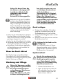
Summary
1 Engine housing
2 Spark plug connector
3 Choke lever
4 Starter handle with starter cable
5 Fuel pump (Primer)

7
NI
IE
6
7 Fuel tank
8 Top shaft tube
9 Eyelet for carrying harness
10 Multifunction handle
11
12 Bottom shaft tube
13 Protective cover
14 Thread cutter
15 Reel capsule
16 Thread reel (not visible)
17 Operating unit
18 Device cable
19 Cable holder
20 On/off switch
21 Throttle lock
22 Throttle
23 Maintenance key
24 Hexagon socket wrench
25 500 ml oil/petrol mixing bottle
26 Carrying harness
27 Body protection
28 3-toothed blade
29 4-toothed blade
B
30 2 screws of the protective cover
31 Shaft holder
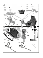
C
32 Safety lever
D
33 Star-shaped knob,
multi-functional handlebar
34 Handlebar bracket
35 Intake (+ large spring),
handlebar bracket
E
36 Tank cover
F
37 Lug of the quick-release device
H
38 Click lock, spool case
39 Thread outlet eye
40 Recess, thread spool
I
J
44 Spark plug
L
M
46 Notch in the thread spool
47 Groove in the thread spool
48 Mounting spindle
49 Washer
50 Conical spring washer
51 Nut
52 Mounting screw
53 Click lock, protective cover
54 Extension, protective cover
D
55 Spring, large
56 Spring, large
57 Screw, gear lubrication
58 Screw, eyelet
A
59 Transport protection,
3-toothed blade
60 Transport protection,
4-toothed blade
Safety Functions
21 Throttle lock
Prevents accidental acceleration
of the engine. The throttle can be
operated only when the throttle
lock is depressed.
20 On/off switch
The on/off switch switches off
the engine. It must be in position
in order to restart the engine.

8
IE NI
13 Protective covers
Protect the operator from acciden-
tal contact with the cutting tool and
foreign bodies being thrown out.
Petrol grass trimmer ................ PBS 2 A1
Engine ............................ 2-stroke engine
Fuel Mix .........................................40:1
Engine capacity ........................42.7 cm³
Max. engine power ......1.35 kW (1.8 HP)
Engine tick over speed ... 2700 - 3400 rpm
Max. cutting speed
With blade ........................ 7850 min
-1
With thread spool ............... 6750 min
-1
Tank capacity ......... 1200 ml / 1200 cm³
Weight (empty tank) ..................... 7.1 kg
Metal cutting blade
Threads
Cutting radius .........................430 mm
Thread thickness ......................2.4 mm
Thread length ............................... 6 m
Blade
Cutting diameter .....................255 mm
Max. rotational speed ...... 10000 min
-1
Sound pressure level (L
pA
) with
blade .............98,47 dB(A), K
pA
= 2,5 dB
thread spool .... 97,60 dB(A), K
pA
= 2,5 dB
Sound power level (L
WA
)
Guaranteed .........................114 dB(A)
Measured with
blade .... 108,47 dB(A); K
WA
= 2,37 dB
thread spool ...............106,80 dB(A);
................................ K
WA
= 1,34 dB
Vibration (a
h
) with blade
Left handle .... 4.796 m/s
2
; K=1.5 m/s
2
Right handle ... 6.336 m/s
2
; K=1.5 m/s
2
Vibration (a
h
) with thread spool
Left handle ... 12.438 m/s
2
; K=1.5 m/s
2
Right handle . 16.719 m/s
2
; K=1.5 m/s
2
The vibration values were determined in
accordance with ISO 22867.
Levels of noise were determined according
to the norms and regulations in the decla-
ration of conformity.
Safety Information
In order to be able to operate the
equipment safely, all instructions
and information in the operating
instructions about safety, assembly
and operation must be followed pre-
cisely. Anyone operating or main-
taining this equipment must be fa-
miliar with the operating instructions
and informed of potential hazards.
Symbols in the Instructions
Warning signs with details for
the prevention of personal and
property damage.
Command signs (instead of the
exclamation mark, the command is
explained) with details for the preven-
tion of damage.
Information signs with information
for better handling of the equipment.
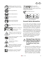
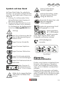
Symbols on the Equipment
On the equipment, there are information
symbols. These convey important information
about the product or information about its use.
• Caution: Special safety measures are
required when handing the equipment!
• The entire operating instructions must
be read and understood before use.
Non-observance of the operating in-
structions may be fatal!
Attention!

9
NI
IE
Read the operating instructions
carefully before using the equip-
ment.
Wear eye protection.
Wear head protection.
Wear ear protection.
Wear protective gloves.
Risk of injury from cuts.
Wear safety boots with sturdy
soles.
Maintain a safety dis-
tance of min. 15 m
from others.
Danger from parts being thrown
out! Keep away from other peo-
ple.
Do not use any circular- or multi-
toothed saw blades!
Risk of injury.
Caution! Hot surfaces –
risk of burns!
Attention! Kickback - be aware
that you may experience kick-
back while working with the
machine.
sound power level L
WA
in dB.
Mix ratio 40:1,
Use ONLY fuel mix
smoking are prohibited.
Use ONLY fuel mix
Start-up Sequence
General Safety Information
Do not allow access by children or by peo-
carefully supervised when they are in the
area of machinery. Observe the regional
and local accident prevention regulations
applicable where you are. The same ap-
plies for all regulations concerning occupa-
tional safety and health in the workplace.
The manufacturer cannot be held liable if
the machines produced by the same are
age to people or property occurs as a
Warning! Always take basic
precautions when using ma-
chinery. Please also observe
all tips and information in
the additional safety infor-
mation.
1. Observe the surrounding conditions un-
der which you are working. The motor-
ised equipment produces toxic fumes
as soon as the engine is running. These
gases may be odourless and invisible.
Therefore, never work with the equip-
ment in enclosed or poorly ventilated

10
IE NI
spaces. Ensure adequate ventilation
when working. Ensure a safe stance in
the wet, snow and ice, on slopes and
on uneven territory.
2. Do not allow strangers to use the
equipment. Visitors and onlookers –
particularly children and people who
from the workplace. Prevent other peo-
ple from coming into contact with the
tools. Do not pass on the equipment
to people who are unfamiliar with the
equipment and its handling.
3. Ensure the safe transport and storage
of the equipment. Always carry the
equipment suspended by the carrying
strap or on the tube. Equipment that
is not in use must be stored in a dry
place as high up as possible or locked
away to be inaccessible.
4. Always use the right tool for any work.
E.g. do not use small tools or acces-
sories for work that should actually be
performed with heavy tools. Use tools
only for the purposes for which they
have been constructed.
5. Ensure appropriate clothing. Clothing
must be appropriate and not impede
you when working. Wear clothing with
cut protection pads.
6. Use personal protective equipment.
Wear safety boots with steel caps /
steel soles and non-slip soles. Wear a
hard hat if there is a risk of falling ob-
jects when working.
7. Wear safety goggles. Objects may be
thrown out. Serious eye injuries may
result.
8. Wear ear protection. Wear personal
sound protection, e.g. earplugs.
9. Hand protection. Wear strong gloves –
leather gloves offer good protection.
10. Operating the equipment. Never work
without the protection on the cutting
tool. Risk of injury from objects being
thrown out.
11. Remove the socket wrench etc. All keys
or similar must be removed before the
equipment is switched on.
12. Stay alert at all times. Pay attention to
what you are doing. Use your com-
mon sense. Do not use motorised tools
when you are tired. Work with the
equipment must not be carried out un-
medications, which impair reactions.
13. Filling with fuel.
-
tions and the respective state/federal
ensure good ventilation. Smoking and
• Always switch off the engine before
care, so any excess pressure present can
be relieved slowly and no fuel sprays
out. The work with the equipment causes
high temperatures on the housing. The
equipment must therefore be allowed to
could ignite and cause serious injuries.
this must be cleared away immediately
and the equipment cleaned.
is sitting properly in order to prevent
it from coming loose as a result of the
vibrations caused during the work.
• Watch out for leaks. Do not start the
engine if fuel is leaking. Risk of death
as a result of burns!
14. Usage duration and breaks. Prolonged
use of this motorised device can lead
to problems with the blood circula-

11
NI
IE
tion in the hands caused by vibrations
(Raynaud’s syndrome). However, the
usage duration can be extended with
suitable gloves or regular breaks. Be
aware that personal tendency to poor
circulation, low external temperatures
and high gripping forces will reduce
the usage duration when working.
15. Be aware of damaged parts. If the
device suffers a heavy impact or is
dropped, check it for signs of damage
and wear before putting it back into op-
eration. Are individual parts damaged?
In case of slight damage ask seriously
whether the tool will nonetheless work
properly and safely. Ensure correct
alignment and adjustment of moving
parts. Do the parts interlock correctly?
Are parts damaged? Is everything cor-
rectly installed? Are all the other require-
ments in place for proper functioning?
Damaged safety devices etc must be
repaired or replaced by authorised peo-
ple if there is no explanation otherwise
in the operating instructions. Defective
switches must be replaced by an au-
thorised body. If repairs are required,
please contact a customer service cen-
tre authorised by us.
16. Always switch off the engine before un-
dertaking adjustments or maintenance
work. This particularly applies for work
on the thread reel.
17. Use only authorised parts. In case of
maintenance and repair, use only iden-
tical spare parts. Contact the service
centre for spare parts.
Warning! The use of other mowing
heads as well as accessories and
attachments that are not explicitly
recommended can result in danger
to people and objects.
The tool is to be used only for the
intended purpose. Any misappro-
priation is regarded as improper
not the manufacturer – is responsible
for property and personal damage
resulting from such improper use.
The manufacturer cannot be held li-
able if machines from the same are
damage occurs as a result.
Caution! A certain residual risk,
which cannot be eliminated, always
remains even in the case of proper
use of the tool. The following po-
tential hazards can be derived from
the type and design of the tool:
• Contact with the unprotected thread
reel (cuts).
• Reaching into the thread reel when it is
running (cuts).
• Hearing damage if no appropriate
protection is worn.
• Dust and gas formation that is harmful
to health if the equipment is used in
enclosed spaces (nausea).
Additional Safety
Regulations
1. Caution! Always keep hands and feet
away from the cutting area, particularly
when starting the equipment. Always
keep the hand on the extra handle free.
2. Always hold the device with both hands
on the multi-functional handlebars.
Always keep the equipment at an ap-
propriately safe distance from the body
and assume a stable body position.
Always use the carrying strap.
3. Always wear safety goggles.
4. Use the equipment only in daylight or

12
IE NI
5. Do not use the equipment in the rain or
on damp grass.
6. Before use or after an impact, check
the equipment for possible damage;
repair if necessary.
7. Do not use the equipment if the safety
devices are damaged or not correctly
installed.
8. Ensure that the engine ventilation slots,
protective cover and cutting device are
always free of dirt or residues.
9. During the work processes, always en-
sure that there are neither people nor
animals within a radius of at least 15
m. Switch off the equipment immedi-
ately if anyone and particularly a child
comes into the range of the machine.
When using the equipment, stones and
other elements that can cause serious
injuries can be thrown out.
10. When the equipment is in operation,
keep away from the moving parts (in
the area of the cutting devices).
After switching off, the cutting head
continues to turn for a few seconds.
11. Before using the equipment, remove
stones, twigs and any other solid mate-
rial from the working area.
Start the machine only as described in
the instructions. It must not be turned
upside down or be in the working posi-
tion when it is started.
Do not cross gravel roads or paths with
the equipment running.
12. The greatest care is required when ex-
tending the cutting thread. Risk of injury
from cuts. After executing these process-
es, reassume the correct working posi-
tion before switching on the equipment.
13. Do not use metallic cutting reels or
saw blades. Note that the equipment
remains in operation for a few seconds
after the switch is released.
14. Switch off the engine when:
- Refuelling the equipment,
- Not using it,
- Leaving it unattended,
- Cleaning it,
- Transporting it from one location to
another,
- Removing or replacing the cutting
device and manually adjusting the
length of the cutting thread.
15. Length of use and breaks. Pro-
longed use of the power device can
lead to problems with the blood circula-
tion in the hands caused by vibrations.
You can however extend your machine
use time by wearing appropriate gloves
or by taking regular breaks. Please en-
sure that if you are susceptible to poor
circulation, low outside temperatures or
strong gripping forces while working,
this may reduce the length of time for
which you are able to work.
16. Carry the trimmer by the upper and
lower shaft tube when it is switched off,
with the cutting unit pointing away from
your body in order to avoid injuries
After the device has been switched off,
the engine head of the scythe is hot.
Make sure that you do not come into
contact with the engine head.
17. You should carry out regular checks to
determine whether the cutting equipment
is stationary when the device is idling.
18. National regulations may specify an
age restriction for the user.
Protective measures against
kickbacks
In the event of a kickback, the
operator will feel a powerful
blow from the petrol-powered
trimmer. This may lead to lo-
sing control of the device and

13
NI
IE
Ensure that the bottom shaft tube is
-
ing the equipment.
4. Dismantling:
Release the handle-fastening screw
(11). Push the safety lever (32) and
pull the two shaft tubes apart.
Mounting the multi-
functional handlebar
1. Place the large spring (55) between
the intake on the upper shaft tube (35)
and the lower section of the handlebar
bracket (34).
2. Place the multi-functional handlebar
(10) and the small spring (56) into the
handlebar bracket (34).
3. Fasten the multi-functional handlebar (10)
to the upper section of the handlebar
bracket (34) and star-shaped knob (33).
Tighten the star-shaped knob (33) by hand.
Initial Operation
Warning! Before initial opera-
tion of the equipment, it must
be checked that the condition
is safe for operation. If there
is any doubt, do not start the
equipment.
Observe the following points in par-
ticular:
• Check the cutting tools for damage and
wear.
• Correct installation of the cutting head
• Easy movement of all switches
• Secure sit of the spark plug connector. If the
connector is loose, sparks can be formed
and thus ignite any leaking fuel-air mix.
• Ensure the handles are clean in order to be
able to guide the equipment safely.
serious injury. You can avoid
kickbacks through caution
and proper technique.
While working with the 3- or 4-tooth bla-
de there is a risk of kickback if the blade
edge hits an obstacle (stone, wood).
• Hold the device with both hands.
• Make sure there are no obstacles on the
ground and do not use the 3- or 4-tooth
blade near fences, metal posts or similar.
Use only properly
sharpened tools. To cut
thick stems, switch the
device to position A.
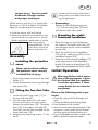
Assembly
Installing the protective
cover
Never use the device without
the protective cover correctly
installed! Risk of injury.
1. Position the protective cover on the shaft
holder (31).
2. Attach the protective cover using the hinge
and screws (30).
Fitting the Two-Part Tube
the top shaft tube (8).
3. Push the safety lever (32) and insert
the two shaft tubes into one another.
Release the safety lever (32). The safety
lever (32) of the upper shaft tube (8)
must latch into the hole provided on the
lower shaft tube (12).
hand.

14
IE NI
• All safety and protective devices must be
properly installed and in place before the
equipment can be started.
The cutting head must be able to run
freely. Before starting the equipment, en-
sure that the cutting head is sitting correctly
and that the moving parts are free.
Warning! If there is any
doubt, seek help with the
operation of this equipment
from a specialist in an au-
thorised service centre.
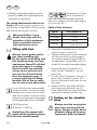
Filling with Fuel
Always ensure good ventila-
tion when handling fuel.
fuel and keep away from any
when the engine is running.
Open the tank cap carefully,
so any excess pressure pre-
sent can be relieved slowly.
Start the equipment min. 3
-
sion in case of non-observance
Use only the fuel mix recommended
in the instructions. The fuel mix ages.
Therefore, do not use fuel mix that is
older than 3 months. In case of non-ob-
servance, the engine can be damaged
and the guarantee will be invalidated.
of the tank is 1200 ml.
Avoid direct skin contact with
petrol and the inhalation of pet-
rol fumes. Health hazard!
with a two-stroke en-
gine and therefore operated exclusively
with a mix of petrol and two-stroke engine
oil in the ratio 40:1.
Table of fuel mixtures:
Petrol Two-stroke oil
1,00 litres 25 ml
3,00 litres 75 ml
5,00 litres 125 ml
Mixing
40 parts of petrol
+ 1 part of oil
• Use quality unleaded petrol with an
octane rating of at least 90.
• Optimum performance will be achieved
with the use of the two-stroke engine
the equipment. If unavailable, use oil in-
tended for air-cooled two-stroke engines.
1. Prepare the petrol/oil mixture in a
clean canister intended for use with
petrol (25).
the oil, then shake the canister. Fill in
the rest of the petrol and shake the can-
ister again.
fuel mixture into the petrol tank (7).
Putting on the shoulder
strap
Always wear the carrying har-
ness when working with the
device. Always turn the device
off before taking off the carry-
ing harness. Risk of accidents.

15
NI
IE
The carrying harness is
equipped with a quick-re-
lease device. Pulling the red
lug (37) releases the device
quickly from the carrying har-
ness in a dangerous situation.
1. Put on the carrying harness (26). The
clip must be situated on the chest.
2. Adjust the strap so the spring clip is
around 10 cm below the hip.
3. Fix the spring clip onto the lifting ring
(9) on the shaft tube of the equipment.
Unhook the device before starting the
engine and fasten it to the carrying
harness once the engine is running.
Place the protective body (27) on
your hip between your body and
the device.
Starting the Engine
Start the engine at least three
Place the appliance on a solid and
even surface. Check that the blade is
not touching any objects or the ground.
Cold start:
1. Make sure that the protective cap on
the thread cutter (
A
14) is removed.
-
face. Make sure that the cutting tool
does not touch either other objects or
the ground.
3. Set the choke lever (3) to position
.
4. Press the fuel pump (primer) (
A
5) 6
times.
5. Set the on/off switch (20)
to position
.
by the upper shaft tube (8). With the
other hand, pull the starter cable on the
starter handle (4) quickly several times
in succession until the engine starts and
then switches off again after around
one section.
Caution! Do not pull the starter
cable out too far - Danger of
breakage!
8. Set the choke lever (3) to the warm
start position
and pull the starter
cable once again to start the strimmer.
The device is now idling.
7. To mow, keep the throttle lock (21)
pressed down and operate the throttle
(22). When the throttle is oper-
ated, the choke lever (3) auto-
matically jumps into the warm
start position
.
8. To switch off the engine, set the on/off
switch (20) to position
0
.
Warm start:
1. Leave the choke lever (3) in its present
position
.
by the upper shaft tube (8). With the
other hand, pull the
starter cable on
the starter handle
(4) quickly several
times in succession until the engine
starts.
Caution! Do not pull the starter
cable out too far - Danger of
breakage!
The device is now idling.
3.
To switch off the engine, set the on/off
switch (20) to position
0
.
If the engine has not started after
two attempts, try a warm start wi-
thout the choke in the warm start po-
sition. If this is not successful, follow
the instructions in the „Troubleshoo-
ting“ section.

16
IE NI
Operation
Working Notes
• When cutting, observe the country-
• Do not cut during commonly applica-
ble quiet periods.
• Solid objects such as stones, metal
pieces or similar must be removed.
These can be thrown out and therefore
result in personal or property damage.
• When cutting in high bushes or
hedges, the working height should be
at least 15 cm. This prevents the risk to
animals, e.g. hedgehogs.
securely with both hands.
• Cut only grass and weeds. Be aware of
roots or tree stumps – risk of tripping.
• Work considerately and endanger no-
body when cutting. Work quietly and
carefully.
• Work only in adequate visibility and
lighting conditions.
• Keep an eye on the cutting head.
• Never cut above shoulder height.
• Never replace the plastic cord with a
steel wire – risk of injury and damage.
• Do not work on a ladder.
• Avoid an abnormal body posture.
Ensure that your footing is secure and
keep your balance at all times.
• Change your working position at regu-
lar intervals in order to prevent becom-
ing tired on one side of your body.
• If the cutting head becomes jammed,
turn the device off immediately, re-
move the spark plug connector and
then remove the cause of the blockage.
Adjusting the carrying
harness eyelet/balanc-
ing out the device
Select the correct position for the carrying
harness eyelet according to whether you are
using a spool or blade.
The thread spool or blade (depending on
which is selected) should be situated as fol-
lows without needing them to be touched
by hand:
The thread spool should lie gently on
the ground.
The blade should be balanced around
20 cm above the ground.
1. Release the screw (58) on the carrying har-
ness eyelet (9) using the hexagon socket
wrench (24) and re-fasten but only gently.
2. Balance the strimmer according to the
above criteria (depending on the cut-
ting unit chosen) by sliding the eyelet
(9) on the shaft tube (8).
3. Tighten the screw (58) once the strim-
mer is in the desired position.
Attaching the cable holders:
4. 4. Fasten the machine cable (
A
18)
using the two cable holders (
A
19) be-
neath the engine head (
A
1) and right
or left from the eyelet (9).
Working using the thread spool
• On small grass areas, hold the equip-
ment at an angle of approx. 30° and
turn evenly to the right and left with a
semi-circular movement.
• The best results are obtained with maxi-
mum grass length of 15 cm. If the grass
is longer, mowing several times is recom-
mended.

17
NI
IE
Working using the 3- or
4-toothed blade
Always wear the harness
and suitable protection cloth-
ing when working with the
device. Wear eye, hearing
and head protection.
Ensure that the blade is in-
stalled correctly. Replace
damaged or blunt tool parts.
There is a risk of injury.
Only use the cutting blade to work
on open, even areas. Carefully in-
spect the area to be cut and remove
all foreign bodies. Avoid hitting
stones, metal or other obstacles. The
blade can be damaged and there is
a risk of kickback by the machine.
• When working, hold the cutter above
the ground and slowly swivel the device
back and forth like a scythe in an equal
arch.
• Do not hold the cutting head at an angle.
• Do not use the device to cut wild growth
or brushwood.
• Regularly check the blades for damage
and replace as needed.
If the Equipment Vibrates
Clean the equipment, remove any grass
remnants present on the cutting head and
in the protective cover.
Care and Maintenance
The maintenance and clean-
ing work must always be
carried out with the engine
switched off and the spark
plug connector removed (
A
2).
• To cut around trees, fence posts or other
obstacles, go slowly around the obsta-
cle with the equipment and cut with the
thread tips.
• Avoid contact with solid obstacles (stones,
walls, board fences etc) otherwise the
thread will quickly wear out. Use the
edge of the protective cover to keep the
equipment at the correct distance
Caution! Do not place the cut-
ting head on the ground dur-
ing operation!
Extending the cutting thread
The equipment comes with a double-thread
tap mechanism, i.e. both threads extend if
the cutting head is tapped on the ground.
1. Hold the equipment in operation over
a grassy area and lightly tap the cut-
ting head a few times on the ground.
This extends the thread.
2. The thread cutter (
A
14) included in the
protective cover (
A
13) cuts the thread
to the desired length.
If the thread ends no longer extend:
• Switch off the equipment.
• Press the reel insert until it stops and
give a strong pull on the thread end.
If no thread ends are visible:
• Replace the thread reel (see chapter on
“Changing the Reel”).
Caution! Thread remnants
may be thrown out and cause
injuries.

18
IE NI
Have any work not described
in these instructions carried
out by our service centre.
Never use metallic threads or
saw blades. The use of such
non-original parts can cause
personal injury and irrepara-
ble damage to the equipment
and will result in immediate
invalidation of the guarantee.
Cleaning the Equipment
• Clean the cutting device and protective
cover of grass and earth after each cut-
ting procedure.
• Always keep the handles clean and
free of grass.
• Clean the equipment with a soft brush
or a damp cloth.
Protect the equipment from
damage! The equipment is to be
neither sprayed with water nor placed
in water. Do not use detergents or sol-
vents. These could cause irreparable
damage to the equipment.
Changing the Reel
The protective cover must be
fully mounted when using
the thread spool. (See Chap-
ter: “Removing/mounting the
protective cover extension”)
1. Switch off the engine.
2. Place the equipment on the
ground and ensure that no fuel
leaks and that the equipment is
safely supported.
3. Block the mounting spindle (48)
using the hexagon socket wrench
(24) as depicted.
Screw the spool case (15) clock-
wise to the mounting spindle (48).
Open the spool case (15) by
-
wards (38) on both sides of the
spool case (15), and remove the
spool case cover.
A Phillips-head screwdriver can
be used to assist in opening the
spool case.
Proceed with caution: do not
damage the spool.
5. Place the new spool (16) into
the spool case cover (15) and
insert the two ends of the thread
through the thread outlets (39).
6. Place the thread spool (16) into
the spool case cover (15) and al-
low the cover to latch back into
the spool case (15).
Ensure that the thread outlets
(39) match the two recesses (40)
in the spool case otherwise the
cover will not close.
7. Screw the spool case (15)
counter-clockwise back onto
the mounting spindle (48). Re-
move the hexagon socket
wrench (24).
8. Pull on both ends of the thread
to release the threads from the
grooves.
9. Trim the thread line to approx.
15 cm to release strain on the
engine when starting and warm-
ing up.
The spare parts which are to be
ordered can be found in the “Spare
parts/accessories“ section

19
NI
IE
Changing blades
The protective cover must be
shortened when using the
blade. (See Chapter: “Remov-
ing/mounting the protective
cover extension”)
1. Switch the engine off.
2. Place the device on the ground in a
stable position and ensure that no fuel
escapes.
3. Block the mounting spindle (48) using
the hexagon socket wrench (24) as de-
picted.
4. Place either the 3-toothed or 4-toothed
blade onto the mounting spindle (48).
The blade can be used on both sides.
5. Fasten the blade using the washer (49),
conical spring washer (50) and nut (51).
6. Remove the hexagon socket
wrench (24).
Removing/mounting the
protective cover extension
If using blades, the protective cover exten-
sion must be removed.
If using the thread spool, the edge of the ex-
tension must be mounted.
1. Release the mounting screw (52) using
a Phillips-head screwdriver.
2. Unclip both sides of the click lock (53).
3. Remove the protective cover extension
(54).
Cleaning the Air Filter
Never operate the equipment with-
dirt enter the engine and result in
damage to the machine. Keep the
1. Switch off the engine.
-
-
ter and allow it to dry in the air
Never use petrol for cleaning!
cover (6) in reverse order.
worn, damaged or dirty (see
“Spare parts/Accessories“).
Changing / Adjusting the
Spark Plug
Worn spark plugs or a spark gap
that is too great will result in a
power reduction of the engine.
1. Switch off the equipment.
2. Take the spark plug connector (2) off of
the spark plug (44).
3. Screw out the spark plug (44) anti-
clockwise using the enclosed mainte-
nance key (see
23).
4. Check the spark gap with the aid of a
feeler gauge (available from specialist
retailers). The electrode gap must
be 0.6 – 0.7 mm.
5. If necessary, adjust the gap by care-
fully bending the spark plug (44) earth
electrode.
6. Clean the spark plug (44) with a wire
brush.
7. Reinsert the cleaned and adjusted
spark plug (44) or replace a damaged
spark plug (44) with a new spark plug
(e.g. “TORCH L8RTC” spark plug).
8. Reattach the spark plug connector (2).

20
IE NI
Sharpening the Thread
Cutter
Do not use the equipment
without a thread cutter or
with a defective thread cutter.
There is a risk of injury!
If the thread cutter blade is
damaged, contact our service
centre.
Wear protective gloves to avoid
cutting injuries.
1. Switch off the equipment.
2. Unscrew the thread cutter (14) from the
protective cover (13).
3. Fix the thread cutter (16) in a vice and
carefully and only ever in one direc-
tion.
4. Screw the thread cutter (14) againg on
the protective cover (13).
The spare parts which are to be
ordered can be found in the “Spare
parts/accessories“ section
Changing the Fuel Filter
Never operate the equipment with-
2. Drain the fuel tank (7) into an appropri-
ate container.
-
ing a hook and remove it by releasing
the small clamp.
removed suction head back in the tank.
5. Close the fuel tank (7) again with the
tank cap (36).
The spare parts which are to be
ordered can be found in the “Spare
parts/accessories“ section
M
Winding up the spool
As an alternative to a new thread spool,
you can purchase a 2.4 mm-thick, 6 m-
long nylon thread in specialist shops and
wind this yourself onto the thread spool.
1. Fold the thread in the middle and place
the middle of the thread in the notch
(46) of the spools (16). Wind up the
two ends in the direction of the arrow
which is shown on the underside
of the spool.
2. Then trap the end of each thread in one
of the grooves (47) on the spool (16).
Pull the threads tight and ensure
that they are parallel in the two
thread channels. In addition, the
more than 3 m of thread in each
channel, as otherwise the automatic
thread mechanism will not function
correctly.
Lubricating the gears
The gears require lubrication after around
10 hours of operation.
1. Release the screw (57) on the gears.
2. Insert around 5 g of commercially-avail-
able lubricating grease into the lubrica-
tion opening on the gearbox housing.
3. Close the gears again using the screw
(57).
Seite wird geladen ...
Seite wird geladen ...
Seite wird geladen ...
Seite wird geladen ...
Seite wird geladen ...
Seite wird geladen ...
Seite wird geladen ...
Seite wird geladen ...
Seite wird geladen ...
Seite wird geladen ...
Seite wird geladen ...
Seite wird geladen ...
Seite wird geladen ...
Seite wird geladen ...
Seite wird geladen ...
Seite wird geladen ...
Seite wird geladen ...
Seite wird geladen ...
Seite wird geladen ...
Seite wird geladen ...
Seite wird geladen ...
Seite wird geladen ...
Seite wird geladen ...
Seite wird geladen ...
Seite wird geladen ...
Seite wird geladen ...
Seite wird geladen ...
Seite wird geladen ...
Seite wird geladen ...
Seite wird geladen ...
Seite wird geladen ...
Seite wird geladen ...
Seite wird geladen ...
Seite wird geladen ...
Seite wird geladen ...
Seite wird geladen ...
Seite wird geladen ...
Seite wird geladen ...
Seite wird geladen ...
Seite wird geladen ...
-
 1
1
-
 2
2
-
 3
3
-
 4
4
-
 5
5
-
 6
6
-
 7
7
-
 8
8
-
 9
9
-
 10
10
-
 11
11
-
 12
12
-
 13
13
-
 14
14
-
 15
15
-
 16
16
-
 17
17
-
 18
18
-
 19
19
-
 20
20
-
 21
21
-
 22
22
-
 23
23
-
 24
24
-
 25
25
-
 26
26
-
 27
27
-
 28
28
-
 29
29
-
 30
30
-
 31
31
-
 32
32
-
 33
33
-
 34
34
-
 35
35
-
 36
36
-
 37
37
-
 38
38
-
 39
39
-
 40
40
-
 41
41
-
 42
42
-
 43
43
-
 44
44
-
 45
45
-
 46
46
-
 47
47
-
 48
48
-
 49
49
-
 50
50
-
 51
51
-
 52
52
-
 53
53
-
 54
54
-
 55
55
-
 56
56
-
 57
57
-
 58
58
-
 59
59
-
 60
60


Parkside PBS 2 A1 Translation Of The Original Instructions
- Kategorie
- Spielzeuge
- Typ
- Translation Of The Original Instructions
in anderen Sprachen
- English: Parkside PBS 2 A1
Verwandte Artikel
Andere Dokumente
-
 Trueshopping BC6502D Assembly & Owners Manual
-
Stanley SPS-900 Bedienungsanleitung
-
Scheppach ZGONIC Yellow Garden Line NEW GENERATION MFH3300-4P Benutzerhandbuch
-
FLORABEST 273489 Bedienungsanleitung
-
Texas BCP4300 Benutzerhandbuch
-
FLORABEST FBS 43 B2 Bedienungsanleitung
-
FLORABEST FBS 43 A1 Operation And Safety Notes Original Operating Instructions
-
Echo RM-4000 Benutzerhandbuch
-
Dolmar MS-246.4 UE Bedienungsanleitung
-
MSW MSW-TRB-3030 Bedienungsanleitung
