Wolf ICBDF304 Installation Instructions Manual
- Kategorie
- Herde
- Typ
- Installation Instructions Manual

DUAL FUEL RANGES
INSTALLATION INSTRUCTIONS
INSTRUCCIONES DE INSTALACIÓN
INSTRUCTIONS D’INSTALLATION
ISTRUZIONI PER L’INSTALLAZIONE
INSTALLATIONSANWEISUNGEN

C O N TAC T
I N F O R M AT I O N
Website:
wolfappliance.com
As you read this use & care information,
take particular note of the CAUTION and
WARNING symbols when they appear.
This information is impor tant for safe and
efficient use of the Wolf equipment.
In addition, this use & care information may
signal an IMPORTANT NOTE which highlights
information that is especially important.
signals a situation where minor injury or
product damage may occur if you do not
follow instructions.
states a hazard that may cause serious
injury or death if precautions are not
followed.
WOLF
®
is a registered trademark of Wolf Appliance, Inc.
I NS TAL LATI ON R E Q U I R E M E N T S
IMPORTANT NOTE: This installation must
be completed by a qualified installer,
service agency or gas supplier.
I
MPORTANT NOTE:
S
ave these installation
instructions for the local inspector’s use.
Please read the entire installation instruc-
tions prior to installation.
Installer:
please retain these instructions
for local inspector’s reference, then leave
them with the homeowner.
Homeowner:
please read and keep these
instructions for future reference and be sure
to read the entire use & care information
prior to use.
IMPORTANT NOTE:
This appliance must be
installed in accordance with local codes. The
correct voltage, frequency and amperage must
be supplied to the appliance from a dedicated,
grounded circuit which is protected by a
properly sized circuit breaker or time delay
fuse. The proper voltage, frequency, and
amperage ratings are listed on the product
rating plate.
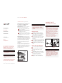
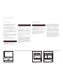
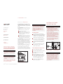
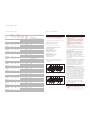
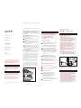
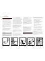
Record the model and serial numbers before
installing the dual fuel range. Both numbers
are listed on the rating plate, located at the far
right of the bottom of the control panel
assembly just above the oven door. Refer to
the illustration below.
I M P O RTA N T
I N S T R U C T I O N S
W
O L F
D
UA L F UE L R AN GE S
IMPORTANT NOTE:
Installation and service must be
performed by a qualified installer,
service agency or the gas supplier.
Do not store or use gasoline or
other flammable vapors and liquids
in the vicinity of this or any other
appliance.
A ventilation hood is recommended
for use with the Wolf dual fuel range.
This range is designed for a floor
installation only. Do not install on a
base.
WHAT TO DO IF YOU SMELL GAS:
Do not try to light any appliance.
Do not touch any electrical switch.
Do not use any phone in your
building.
Immediately call your gas supplier
from a neighbor’s phone. Follow the
gas supplier’s instructions.
If you cannot reach your gas
supplier, call the fire department.
If the information in this book is
not followed exactly, a fire or
explosion may result, causing
property damage, personal injury
or death.
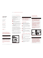
R AT I N G P L AT E
I N F O R M AT I O N
Model Number
Serial Number
Rating plate location.
Location of
rating plate
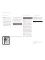
ANTI-TIP
DEVICE
Location of anti-tip
device.
A
NTI-TIP
DEVICE
ENGAGED
Anti-tip device
engaged.
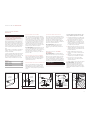
A child or adult can tip the range and be
k
illed.
V
erify the anti-tip device has been properly
installed and engaged. See the illustrations
b
elow for how to verify correct installation.
Ensure the anti-tip device is re-engaged
when the range is moved. See the illustra-
tions below for how to verify correct
installation.
Do not operate the range without the anti-
tip device in place and engaged.
Failure to do so can result in death or
serious burns to children or adults.
To reduce the risk of burns, do not move
this apppliance while hot. This appliance is
provided with casters to facilitate
movement. To reduce the risk of injury due
to tipping of the appliance, verify the rein-
stallation of this appliance into the anti-tip
device provided, and lock the casters after
returning the appliance to the original
installed position.

3
B EF OR E YO U S TA RT
Proper installation is your responsibility.
Installations must be performed by a
qualified or licensed contractor, plumber or
g
as fitter, qualified or licensed by the state,
province or region where this appliance is
b
eing installed. You must also ensure that
electrical installation is adequate and
conforms with all local codes and
ordinances.
Proper gas supply must be available; refer
to gas supply requirements on page 9.
Electrical ground is required; see electrical
requirements on page 10.
Check the location where the range will be
installed. The location should be away from
strong draft areas, such as windows, doors
and strong heating vents or fans. Do not
obstruct the flow of air. The area in which
you are installing this appliance must have
an adequate supply of fresh air to ensure
proper combustion and ventilation.
Make sure you have everything necessary
for proper installation. It is the responsibil-
ity of the installer to comply with the instal-
lation clearances specified on the product
rating plate. The rating plate is located at
the far right of the bottom of the control
panel assembly just above the oven door.
All openings in the wall or floor where the
range is to be installed must be sealed.
When installing the range under existing
cabinets where the installation does not
meet the minimum cabinet clearances,
install a ventilation hood or other non-
combustible surface above the range to
avoid burn hazards. Refer to minimum
clearances on page 3.
V EN TI LATI ON O P T I O N S
IMPORTANT NOTE:
It is recommended that
you operate the Wolf dual fuel range with a
pro ventilation hood. Contact your Wolf dealer
f
or details.
IMPORTANT NOTE:
When installing a ventila-
tion hood, refer to the specific requirements
of the hood for the minimum dimension to
countertop.
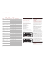
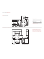
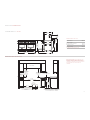
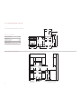
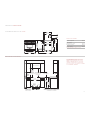
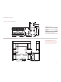
I NS TAL LATI ON S P E C I F I C AT I O N S
Wolf dual fuel ranges come in 762 mm,
914 mm, 1219 mm and 1524 mm widths.
Illustrations on pages 4–7 provide the overall
dimensions and installation specifications for
each width of dual fuel range.
Each range is designed to fit between cabinets
set at the distance specified by the unit. For
example, a 914 mm range will fit a 914 mm
opening. The exception is the 1524 mm unit
which will require a 1530 mm opening.
IMPORTANT NOTE:
Cabinet opening dimen-
sions shown in the installation specifications
illustrations must be used. These dimensions
provide for required clearances.
Each unit is designed with a terminal block on
the rear of the range. The terminal block will
also accept an appliance power cord. Have a
qualified electrician or installer wire your unit
from the electrical supply, through the
knockout in the unit base and to the terminal
block on the range.
IMPORTANT NOTE:
Locate the electrical
supply within dimensions shown in the
installation specifications illustrations and
flush with back wall.
Refer to the installation specifications illustra-
tion for your model on pages 4–7 for the exact
rough opening dimensions and location of the
gas supply and electrical.
Wolf dual fuel ranges using natural gas will
operate up to an altitude of 2438 m without
any adjustment. Natural gas and LP gas instal-
lations from 2438 m to 3353 m need the high
altitude conversion kit. Contact your Wolf
dealer for details.
I
N STA LL AT IO N
I
N S T RU C T I O N S
I NS TAL LATI ON S P E C I F I C AT I O N S
M I N I M U M C L E A R A N C E S
IMPORTANT NOTE:
Caution must be used in
planning the proper installation of the Wolf
dual fuel range to avoid fire or damage to
adjacent cabinetry or kitchen equipment.
Be sure to follow the minimum clearances
e
stablished in the finished rough opening
dimensions.
Refer to the installation specifications illustra-
tion for your model on pages 4–7 for the exact
rough opening dimensions.
Maintain the following clearances to
combustible materials:
Minimum 457 mm clearance from bottom
of upper cabinet to countertop, within
152 mm minimum side clearance.
Minimum 762 mm clearance between coun-
tertop and bottom of wood or metal
cabinet, which is protected by not less than
6 mm flame retardant millboard covered
with not less than No. 28 MSG sheet steel,
.4 mm stainless steel, or .6 mm aluminum
or .5 mm copper.
Minimum 914 mm clearance between coun-
tertop and bottom of an unprotected wood
or metal cabinet.
Bottom of ventilation hood must be
762 mm minimum to 914 mm maximum
from countertop.
I S L A N D | P E N I N S U L A I N S T A L L AT I O N S
For island installations,
the range should
not be installed within an enclosure having an
adjacent rear wall less than 305 mm from the
rear of the unit that rises above the countertop.
F
or peninsula installations,
t
he range must
have a 152 mm minimum clearance to the side
wall, left or right side, and 305 mm minimum
clearance to the rear wall.
Refer to the installation specifications illustra-
tion for your model on pages 4–7 for the exact
rough opening dimensions.
A C C E S S O R I E S
Optional accessories are available through your
Wolf dealer. To obtain local dealer information,
visit the international section of our website,
wolfappliance.com.
Failure to locate the range without the
proper clearances will result in a fire
hazard.

4
W
O L F
D
UA L F UE L R AN GE S
330 mm
LOCATION OF
ELECTRICAL
914 mm
937 mm
TO
COOKING
SURFACE
762 mm min
COUNTERTOP TO
COMBUSTIBLE
MATERIALS
VENTILATION HOOD
457 mm min
TO COUNTERTOP
LOCATION OF GAS AND
ELECTRICAL EXTENDS 57 mm
ON FLOOR FROM BACK WALL
762 mm
FINISHED ROUGH
OPENING WIDTH
83 mm
216
mm
254 mm
LOCATION
OF GAS
SUPPLY
762 mm min TO
914 mm max
TO BOTTOM OF
VENTILATION HOOD
ISLAND INSTALLATIONS: 305 mm MINIMUM
CLEARANCE FROM BACK OF RANGE TO
COMBUSTIBLE REAR WALL ABOVE COUNTERTOP–
0 mm TO NON-COMBUSTIBLE MATERIALS
330 mm
max
152 mm
min TO
COMBUSTIBLE
MATERIALS
(BOTH SIDES)
759 mm
OVERALL WIDTH
937
m
m
ISLAND
TRIM
1165
mm
WITH
254 mm
RISER
1
419
mm
W
ITH
508 mm
RISER
1038
mm
WITH
1
27 mm
RISER
1194 mm
664 mm
635 mm
613 mm
6
99 mm
235
mm
749 mm
OVERALL DEPTH
*937 mm MIN TO 991 mm MAX.
9
11
mm
937 mm
OVERALL
HEIGHT TO
COOKING
S
URFACE*
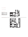
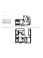
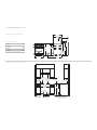
I N S TA L L AT I O N S P E C I F I C AT I O N S
O V E R A L L D I M E N S I O N S
O
verall Width 759 mm
O
verall Height
(to cooking surface) 937 mm
O
verall Depth 749 mm
Opening Width 762 mm
Dimensions may vary to
±
3 mm.
7 62 mm D U A L F U E L R A N G E

5
I
N STA LL AT IO N
I
N S T RU C T I O N S
483 mm
LOCATION OF
ELECTRICAL
914
mm
937 mm
TO
COOKING
SURFACE
VENTILATION HOOD
457 mm min
TO COUNTERTOP
LOCATION OF GAS AND
ELECTRICAL EXTENDS 57 mm
ON FLOOR FROM BACK WALL
914 mm
FINISHED ROUGH OPENING WIDTH
83 mm
216
mm
381 mm
LOCATION
OF GAS
SUPPLY
762 mm min TO
914 mm max
TO BOTTOM OF
VENTILATION HOOD
914 mm min
COUNTERTOP
TO COMBUSTIBLE
MATERIALS
1118 mm min
FOR CHARBROILER
ISLAND INSTALLATIONS: 305 mm MINIMUM
CLEARANCE FROM BACK OF RANGE TO
COMBUSTIBLE REAR WALL ABOVE COUNTERTOP–
0 mm TO NON-COMBUSTIBLE MATERIALS
330 mm
max
152 mm min
TO
COMBUSTIBLE
MATERIALS
(BOTH SIDES)
911 mm
OVERALL WIDTH
937
m
m
ISLAND
TRIM
1165
mm
WITH
254 mm
RISER
1
419
mm
W
ITH
508 mm
RISER
1038
mm
WITH
1
27 mm
RISER
1194 mm
664 mm
635 mm
613 mm
6
99 mm
235
mm
749 mm
OVERALL DEPTH
*937 mm MIN TO 991 mm MAX.
9
11
mm
937 mm
OVERALL
HEIGHT TO
COOKING
S
URFACE*
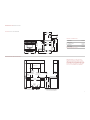
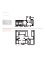
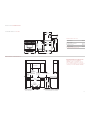
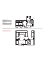
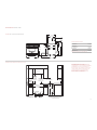
I N S TA L L AT I O N S P E C I F I C AT I O N S
O V E R A L L D I M E N S I O N S
O
verall Width 911 mm
O
verall Height
(to cooking surface) 937 mm
O
verall Depth 749 mm
Opening Width 914 mm
Dimensions may vary to
±
3 mm.
9 14 mm D U A L F U E L R A N G E S
IMPORTANT NOTE: In non-island applications,
a minimum 127 mm riser is required for model
ICBDF366 and minimum 254 mm riser required for
models ICBDF364C and ICBDF364G installed against
a combustible surface. The island trim and 127 mm
riser may only be used against a non-combustible
surface for models ICBDF364C and ICBDF364G.

6
W
O L F
D
UA L F UE L R AN GE S
330 mm
LOCATION OF
ELECTRICAL
914
mm
937 mm
TO
COOKING
SURFACE
VENTILATION HOOD
LOCATION OF GAS AND
ELECTRICAL EXTENDS 57 mm
ON FLOOR FROM BACK WALL
ISLAND INSTALLATIONS: 305 mm MINIMUM
CLEARANCE FROM BACK OF RANGE TO
COMBUSTIBLE REAR WALL ABOVE COUNTERTOP–
0 mm TO NON-COMBUSTIBLE MATERIALS
1219 mm
FINISHED ROUGH OPENING WIDTH
610 mm
83 mm
254 mm
LOCATION
OF GAS
SUPPLY
457 mm min
TO COUNTERTOP
762 mm min TO
914 mm max
TO BOTTOM OF
VENTILATION HOOD
914 mm min
COUNTERTOP
TO COMBUSTIBLE
MATERIALS
1118 mm min
FOR CHARBROILER
330 mm
max
152 mm min
TO
COMBUSTIBLE
MATERIALS
(BOTH SIDES)
1216 mm
OVERALL WIDTH
937
m
m
ISLAND
TRIM
1165
mm
WITH
254 mm
R
ISER
1
419
mm
WITH
508 mm
RISER
1038
mm
W
ITH
127 mm
RISER
1194 mm
664 mm
635 mm
613 mm
6
99 mm
235
mm
749 mm
OVERALL DEPTH
*937 mm MIN TO 991 mm MAX.
9
11
mm
937 mm
OVERALL
HEIGHT TO
C
OOKING
SURFACE*
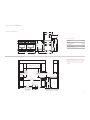
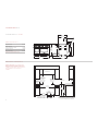
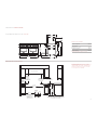
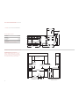
I N S TA L L AT I O N S P E C I F I C AT I O N S
O V E R A L L D I M E N S I O N S
Overall Width 1216 mm
Overall Height
(to cooking surface) 937 mm
Overall Depth 749 mm
Opening Width 1219 mm
Dimensions may vary to
±
3 mm.
1 21 9 m m D UA L F U E L R A N G E S
IMPORTANT NOTE: In non-island applications, a
minimum 254 mm riser is required for all 1219 mm
models installed against a combustible surface.
The island trim and 127 mm riser may only be used
against a non-combustible surface.

7
I
N STA LL AT IO N
I
N S T RU C T I O N S
330 mm
LOCATION OF
ELECTRICAL
914
mm
937 mm
TO
COOKING
SURFACE
VENTILATION HOOD
LOCATION OF GAS AND
ELECTRICAL EXTENDS 57 mm
ON FLOOR FROM BACK WALL
83 mm
787 mm
254 mm
LOCATION
OF GAS
SUPPLY
1530 mm
FINISHED ROUGH OPENING WIDTH
457 mm min
TO COUNTERTOP
762 mm min TO
914 mm max
TO BOTTOM OF
VENTILATION HOOD
914 mm min
COUNTERTOP
TO COMBUSTIBLE
MATERIALS
1118 mm min
FOR CHARBROILER
ISLAND INSTALLATIONS: 305 mm MINIMUM
CLEARANCE FROM BACK OF RANGE TO
COMBUSTIBLE REAR WALL ABOVE COUNTERTOP–
0 mm TO NON-COMBUSTIBLE MATERIALS
330 mm
max
152 mm min
TO
COMBUSTIBLE
MATERIALS
(BOTH SIDES)
1527 mm
OVERALL WIDTH
937
m
m
ISLAND
TRIM
1165
mm
WITH
254 mm
R
ISER
1
41
mm
WITH
508 mm
RISER
1038
mm
W
ITH
127 mm
RISER
1194 mm
664 mm
635 mm
613 mm
6
99 mm
235
mm
749 mm
OVERALL DEPTH
*937 mm MIN TO 991 mm MAX.
9
11
mm
937 mm
OVERALL
HEIGHT TO
C
OOKING
SURFACE*
I N S TA L L AT I O N S P E C I F I C AT I O N S
O V E R A L L D I M E N S I O N S
O
verall Width 1527 mm
O
verall Height
(to cooking surface) 937 mm
O
verall Depth 749 mm
Opening Width 1530 mm
Dimensions may vary to
±
3 mm.
1 52 4 m m D UA L F U E L R A N G E S
IMPORTANT NOTE: In non-island applications, a
minimum 254 mm riser is required for all 1524 mm
models installed against a combustible surface.
The island trim and 127 mm riser may only be used
against a non-combustible surface.

8
U NPACK T H E R A N G E
Remove and discard all packing materials,
including cardboard and tape on the outside of
the range and inside the oven cavity.
R
emove the box containing the oven racks,
oven rack guides and broiler pan from inside
the oven cavity. Be sure to do this for both
oven cavities on the 1524 mm range.
Remove the burner grates and styrofoam off
the top cooking surface. Be sure to remove the
burner caps packaged in styrofoam below the
burner grates.
Do not discard the angle iron supplied with the
range. This is the anti-tip bracket and must be
installed with the unit. Refer to anti-tip bracket
installation on page 11.
Carefully lift the range off the pallet and
remove the styrofoam from the bottom of the
unit.
IMPORTANT NOTE:
Before moving the range
into position, protect any finished flooring with
appropriate materials to avoid damage to the
floor.
The rear of the range has rolling casters which
allows for easy movement of the range by
picking up on the front of the unit. Refer to the
illustration below.
The dual fuel range comes from the factory at
an overall height of 911 mm from floor to the
top of the bullnose, before any height adjust-
ment. The legs and casters allow for 54 mm
height adjustment. Refer to the illustration
below. Use a 19 mm socket to adjust the rear
casters. Refer to the installation specifications
illustration for your model on pages 4–7 for
additional dimensions.
W
O L F
D
UA L F UE L R AN GE S
Casters allow for 54 mm
height adjustment
Rolling casters.
Do not lift the range by the oven door
h
andle(s). This will damage the oven door
and hinges.
The dual fuel range is very heavy. Use
caution when lifting and moving the unit.
Secure oven door(s) closed before
moving the unit.
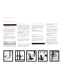
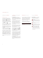
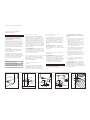
OVE N DOO R R E M O VA L
If removal of the oven door(s) is necessary, a
hinge pin, supplied with the range, will need to
be inserted in the appropriate hinge arm. For
e
ach oven door, only one hinge arm is spring
loaded, requiring use of the hinge pin for
r
emoval of the oven door. The hinge pin will
be found taped to the inside of the oven door.
For 762 mm and 914 mm ranges, the hinge pin
will be inserted through the hole in the right
hinge arm (facing the unit). On 1219 mm and
1524 mm ranges, the spring hinges are located
on the outer edges of the unit. On these units,
the left oven door will have the spring hinge
on the left side and the right oven door will
have the spring hinge on the right side. Refer
to the illustrations below for the location of the
spring hinge(s) for your model.
Place Hinge Pin on
Spring Hinge Side of Door
Place Hinge Pins on
Spring Hinge Side of Door
Spring hinge location for 762 mm
and 914 mm ranges.
Spring hinge locations for 1219 mm
and 1524 mm ranges.
Failure to insert the hinge pin in the
a
ppropriate hinge arm will cause damage
to the range. Minor injuries may occur.
IMPORTANT NOTE:
The oven door(s) should
not be removed unless it is necessary to fit the
range through a tight doorway. Door removal
should only be done by a qualified service
technician or installer. Door removal and rein-
stallation may cause damage to the oven
porcelain interior.

9
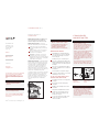
OVE N DOO R R E M O VA L
If removal of the oven door(s) is necessary,
follow these steps:
1)
Remove the lower kickplate assembly to
a
ccess the lower hinge retainer mounting
screws.
2)
Open the oven door to its fully opened
position and remove both upper and lower
hinge retainer mounting screws. The oven
gasket may have to be moved slightly to
access the bottom screws.
3)
After removing the mounting screws, move
the hinge retainer plate forward slightly.
The hinge retainer plate will remain on the
door hinge assembly after the mounting
screws have been removed.
4)
Insert the supplied door hinge pin through
the hole in the appropriate hinge arm. Refer
to the illustration below.
5
)
C
arefully close the oven door to about a
60° angle from horizontal and lift the door
away from the oven. A slight rocking
motion may be required for removal.
6)
For 1219 mm and 1524 mm ranges,
complete these steps for both oven doors.
IMPORTANT NOTE:
The dual fuel range must
be connected to a regulated gas supply.
The rating plate, located at the far right of the
bottom of the control panel assembly just
above the oven door, has information on the
type of gas that should be used. If this infor-
mation does not agree with the type of gas
available, check with the local gas supplier.
A compatible ISO 7-1 gas inlet thread is
provided on all units. Please contact your local
Wolf dealer if an ISO 228-1 or other gas inlet
thread is required. Pipe joint compounds,
suitable for use with LP gas should be used.
For LP gas, piping or tubing size can be 13 mm
minimum. LP gas suppliers usually determine
the size and materials used on the system.
If local codes permit, a flexible metal appliance
connector is recommended for connecting this
range to the gas supply line. Do not kink or
damage the flexible connector when moving
the range.
If rigid pipe is used as a gas supply line, a
combination of pipe fittings must be used to
obtain an in-line connection to the range. All
strains must be removed from the supply and
gas lines so the range will be level and in line.
E
XPLOSION HAZARD—
S
ecurely tighten all gas connections.
Failure to do so can result in explosion,
f
ire or death.
G AS S UP PLY R E Q U I R E M E N T S G AS S UP PLY C O N N E C T I O N
IMPORTANT NOTE:
All connections to the gas
piping must be wrench-tightened. Do not make
connections too tight. Do not allow the pipes
t
o turn when tightening fittings as the tubing
in the burner box may bend and begin to leak.
I
N STA LL AT IO N
I
N S T RU C T I O N S
Hinge
Retainer
Plate
Upper Mounting
Screw
Hinge
Pin
Kickplate
Oven door removal.
I M P O RTA N T N O T E
This installation must conform with local codes
and ordinances.
Do not lift or carry the oven door by the
door handle.
Never test for a gas leak with a match or
other flame.

10
W
O L F
D
UA L F UE L R AN GE S
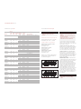
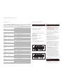
G AS
R AT I N G
Model #
T
otal Heat
Ouput
(Gas)
Gas
Units
E
lectrical
Rating
(Amps)
Appliance
Category
T
ypes and
Pressures
(mbar) Country of Designation
ICBDF304 17.1 kW 20
I
2H G20 at 20
A
T, DK, EE, FI, GR, IE, IT, LT, NO, PT, ES,
S
E, SI, SK, GB, CH
I2E G20 at 20 DE, PL
I2E+ G20 at 20/25 BE, FR
ICBDF304-LP 1051 g/h 20 I3P G31 at 37 BE, CZ, FR, GR, IE, NL, NO, PT, ES, GB, CH
ICBDF364C 22.7 kW 20
I
2H G20 at 20
A
T, DK, EE, FI, GR, IE, IT, LT, NO, PT, ES,
S
E, SI, SK, GB, CH
I2E G20 at 20 DE, PL
I2E+ G20 at 20/25 BE, FR
I
CBDF364C-LP 1425 g/h 20 I3P G31 at 37 BE, CZ, FR, GR, IE, NL, NO, PT, ES, GB, CH
ICBDF364G 22.7 kW 20
I
2H G20 at 20
A
T, DK, EE, FI, GR, IE, IT, LT, NO, PT, ES,
SE, SI, SK, GB, CH
I2E G20 at 20 DE, PL
I2E+ G20 at 20/25 BE, FR
ICBDF364G-LP 1425 g/h 20 I3P G31 at 37 BE, CZ, FR, GR, IE, NL, NO, PT, ES, GB, CH
ICBDF366 26.7 kW 20
I2H G20 at 20
AT, DK, EE, FI, GR, IE, IT, LT, NO, PT, ES,
SE, SI, SK, GB, CH
I2E G20 at 20 DE, PL
I2E+ G20 at 20/25 BE, FR
ICBDF366-LP 1632 g/h 20 I3P G31 at 37 BE, CZ, FR, GR, IE, NL, NO, PT, ES, GB, CH
ICBDF484CG 28.3 kW 30
I2H G20 at 20
AT, DK, EE, FI, GR, IE, IT, LT, NO, PT, ES,
SE, SI, SK, GB, CH
I2E G20 at 20 DE, PL
I2E+ G20 at 20/25 BE, FR
ICBDF484CG-LP 1800 g/h 30 I3P G31 at 37 BE, CZ, FR, GR, IE, NL, NO, PT, ES, GB, CH
ICBDF486C 32.3 kW 30
I2H G20 at 20
AT, DK, EE, FI, GR, IE, IT, LT, NO, PT, ES,
SE, SI, SK, GB, CH
I2E G20 at 20 DE, PL
I2E+ G20 at 20/25 BE, FR
ICBDF486C-LP 2007 g/h 30 I3P G31 at 37 BE, CZ, FR, GR, IE, NL, NO, PT, ES, GB, CH
ICBDF486G 32.3 kW 30
I2H G20 at 20
AT, DK, EE, FI, GR, IE, IT, LT, NO, PT, ES,
SE, SI, SK, GB, CH
I2E G20 at 20 DE, PL
I2E+ G20 at 20/25 BE, FR
ICBDF486G-LP 2007 g/h 30 I3P G31 at 37 BE, CZ, FR, GR, IE, NL, NO, PT, ES, GB, CH
ICBDF484DG 28.3 kW 30
I2H G20 at 20
AT, DK, EE, FI, GR, IE, IT, LT, NO, PT, ES,
SE, SI, SK, GB, CH
I2E G20 at 20 DE, PL
I2E+ G20 at 20/25 BE, FR
ICBDF484DG-LP 1800 g/h 30 I3P G31 at 37 BE, CZ, FR, GR, IE, NL, NO, PT, ES, GB, CH
ICBDF484F 21.9 kW 30
I2H G20 at 20
AT, DK, EE, FI, GR, IE, IT, LT, NO, PT, ES,
SE, SI, SK, GB, CH
I2E G20 at 20 DE, PL
I2E+ G20 at 20/25 BE, FR
ICBDF484F-LP 1342 g/h 30 I3P G31 at 37 BE, CZ, FR, GR, IE, NL, NO, PT, ES, GB, CH
ICBDF604CF 27.5 kW 40
I2H G20 at 20
AT, DK, EE, FI, GR, IE, IT, LT, NO, PT, ES,
SE, SI, SK, GB, CH
I2E G20 at 20 DE, PL
I2E+ G20 at 20/25 BE, FR
ICBDF604CF-LP 1716 g/h 40 I3P G31 at 37 BE, CZ, FR, GR, IE, NL, NO, PT, ES, GB, CH
ICBDF606CG 37.9 kW 40
I2H G20 at 20
AT, DK, EE, FI, GR, IE, IT, LT, NO, PT, ES,
SE, SI, SK, GB, CH
I2E G20 at 20 DE, PL
I2E+ G20 at 20/25 BE, FR
ICBDF606CG-LP 2381 g/h 40 I3P G31 at 37 BE, CZ, FR, GR, IE, NL, NO, PT, ES, GB, CH
R E Q U I R E D P O W E R S U P P LY
Single phase: 220-240V AC; 50/60 Hz
3phase: 380-415V AC; 50/60 Hz
M A X I M U M C O N N E C T E D L O A D
762 mm and 914 mm Dual Fuel ranges:
Single phase: 20 amps
3phase: 20 amps
1219 mm Dual Fuel ranges:
Single phase: 30 amps
3phase: 20 amps
1524 mm Dual Fuel ranges:
Single phase: 40 amps
3phase: 20 amps
Refer to the wiring diagram showing the
connections for each lead to the terminal box
on the unit.
E LE CT RI CA L R E Q U I R E M E N T S
The complete appliance must be properly
grounded at all times when electrical
p
ower is applied.
NOTE: Improper connection can result in
a fire hazard.
Before obtaining access to terminals, all
supply circuits must be disconnected.
Verify that power is disconnected from
the electrical box before proceeding.
Open the terminal box to expose the screws
with corresponding numbers. Run the cord
through the strain relief hole and into the
terminal box.
For Single Phase Install (Line, Neutral,
Ground):
Loosen the 1, 5, and ground screws.
Attach the Neutral wire to the number 5
position. Line should be attached to the 1
postion and attach the ground to the corre-
sponding ground screw.
For 3phase Install (L1, L2, L3, Neutral,
Ground):
Loosen the 1, 2, 3 and remove the
copper bars. Loosen 5 and ground screws.
Attach L1 to position 1. L2 to position 2. L3 to
position 3. Neutral wire to position 5 and attach
the ground to the corresponding ground screw.
IMPORTANT NOTE:
Connection of this appli-
ance should be through a fused connection
unit or a suitable isolator, which complies with
national and local safety regulations. The
on/off switch should be easily accessible after
the appliance has been installed. If the switch
is not accessible after installation (depending
on country) an additional means of disconnec-
tion must be provided for all poles of the
power supply. When switched off there must
be an all pole contact gap of 3 mm in the
isolator switch. This 3 mm contact disconnect
gap must apply to any isolator switch, fuses
and/or relays according to EN60335.
Copper bars must be removed from posi-
tions 1, 2, and 3 when connecting to
3phase power.
Single phase wiring diagram
3phase wiring diagram

11
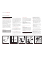
D RY WA L L A P P L I C AT I O N S
After properly positioning the anti-tip bracket,
use wall anchors to fasten it to the wall. Using
a Philips screwdriver or a low rpm screw gun,
drive the anchor into the surface of the wall-
board until the two cutting blades penetrate
t
he surface. Use gentle forward pressure to
rotate the collar until flush with the surface of
the wall. Refer to the illustrations below. Use
#8 screws and flat washers to fasten the anti-
tip bracket to the wall.
IMPORTANT NOTE:
Pre-drill holes if difficulty
is encountered during installation of the wall
anchor. For hard wallboard or double-board
construction, use a 6 mm drill bit. For solid
plaster, use a 11 mm drill bit.
W O O D F L O O R A P P L I C AT I O N S
After properly positioning the anti-tip bracket,
drill 5 mm pilot holes through the floor. Use
#12 screws and flat washers to secure the
bracket to the floor.
C O N C R E T E F L O O R A P P L I C AT I O N S
After properly positioning the anti-tip bracket
drill 10 mm holes into the concrete a minimum
of 38 mm deep. Use 10 mm wedge anchors to
secure the bracket to the floor.
A N T I - T I P B O LT A D J U S T M E N T
Once the bracket is secured in place, adjust the
anti-tip bolt at the back of the range so the top
of the washer is 22 mm maximum from the
floor. Slide the range into the opening and
verify the anti-tip bolt is engaged. Refer to the
i
llustrations below.
IMPORTANT NOTE:
The top of the range
must be level. Use the adjustable front legs
and the rear casters to level the range.
Raise the unit to its desired height by adjusting
the front legs and rear casters. The legs and
casters allow for 54 mm height adjustment.
Use a 19 mm socket to adjust the rear casters.
The front legs are adjusted by rotating the
bottom hexagonal portion of the leg.
The anti-tip bracket can be installed by
securing it to the wall or floor using the
supplied hardware.
Refer to the chart and illustration below to
determine the proper distance from the left
side of the opening to the anti-tip bracket. This
will ensure the anti-tip bolt properly engages
the bracket.
M O D E L A
762 mm Range 5 mm
914 mm Range 14 mm
1219 mm Range 5 mm
1524 mm Range 8 mm
A NT I- TI P BR AC KE T I N S TA L L AT I O N
OVE N DOO R R E I N S TA L L AT I O N
IMPORTANT NOTE:
The oven door(s) should
not be removed unless it is necessary to fit the
range through a tight doorway. Door removal
should only be done by a qualified service
technician or installer. Door removal and rein-
stallation may cause damage to the oven
porcelain interior.
A
ANTI-TIP
BRACKET
Anti-tip bracket location.
ANTI-TIP
BRACKET
WALL
ANCHOR
Wall anchor installation.
22 mm MAX
ANTI-TIP
BOLT
Anti-tip bolt adjustment.
ANTI-TIP
DEVICE
ENGAGED
Anti-tip bolt engaged.
I
N STA LL AT IO N
I
N S T RU C T I O N S
Hinge
Retainer
Plate
Upper Mounting
Screw
Hinge
Pin
Kickplate
Oven door reinstallation.
If oven door(s) have been removed, follow
these steps to reinstall:
1)
Hold the oven door on both sides and
p
osition it with door hinges aligned with
openings in the oven frame.
2)
Holding the oven door at an approximate
30° angle from vertical, slide the hinges into
the openings until the bottom hinge arms
drop fully into the hinge receptacles.
3)
Open the oven door to its fully opened
position. Remove the hinge pin from the
appropriate hinge arm. Refer to the
illustration below.
4)
Reinstall the hinge retainer plate with upper
and lower mounting screws.
5)
Open and close the door completely to
ensure that it is properly installed.
6)
For 1219 mm and 1524 mm ranges,
complete these steps for both oven doors.
7)
Reinstall the lower kickplate assembly.
IMPORTANT NOTE:
Fully extend the hinge
claw which is opposite the hinge pin location
and insert into the hinge pocket prior to insert-
ing opposite side. This will ease the installa-
tion of the oven door.
T
his range can tip. Injury to persons
could result. Install the anti-tip bracket
supplied with the range.
Do not lift or carry the oven door by the
door handle.

12
W O L F D UA L F UE L R AN GE S
R EM OV I NG T H E R A N G E
If removing the dual fuel range is necessary for
cleaning or service, shut off the gas supply.
Disconnect the gas supply and electrical
c
onnections to the unit, then remove the
range. Reinstall in the reverse order and be
s
ure to check the gas connection for leaks.
Refer the Wolf dual fuel ranges use & care
information included with the range for
cleaning recommendations.
T ROU B LE S H O O T I N G
IMPORTANT NOTE:
If the dual fuel range
does not operate properly, follow these
troubleshooting steps:
V
erify that power is being supplied to the
range.
Check the gas supply and electrical
connections to ensure that the installation
has been completed correctly.
Check that gas valves are turned to the ON
position.
Follow troubleshooting procedures as
described in the Wolf dual fuel ranges
use & care information.
If the range still does not work, contact a
Wolf dealer. Do not attempt to repair the
range yourself. Wolf
is not responsible for service required to
correct a faulty installation.
Be sure to disconnect the gas supply and
electrical connections before removing
the range.
V ER IF Y R A N G E O P E R AT I O N
IMPORTANT NOTE:
Prior to operating the
range, be sure to read the entire Wolf dual fuel
ranges use & care information included with
the range for important safety and service
i
nformation.
Install the oven rack guides onto the shoulder
screws located on the interior side walls of the
oven. Slide the oven racks onto the support
racks within the oven. There are three racks
per oven, except for the 457 mm oven which
has two racks. Place the broiler pan and grid
on a rack within the oven, if desired.
Turn on the power supply to the range. The
control panel should be closed (no visible
control pads). Touch and slightly depress the
flame graphic on the hidden control panel to
open.
Set the time of day by pressing the touch
pad, scroll to the desired time by using the
or arrows, then touch . After setting the
time, the hidden control panel can be closed.
The control panel does not have to be open to
operate the oven.
Select any of the eight cooking modes by
using the oven control knob bezel and turning
to the desired mode. Once the mode has been
selected, the temperature can be adjusted by
turning the temperature readout knob clock-
wise to increase the temperature or counter-
clockwise to decrease the temperature. Verify
that the oven is coming up to temperature. For
a 1219 mm or 1524 mm range, follow this
procedure for the both ovens.
IMPORTANT NOTE:
A small amount of
smoke and odor may be noticed during the
initial break-in period. Refer to the use & care
information for additional information.
S UR FACE B U R N E R S
I N I T I A L L I G H T I N G
The surface burners use electronic igniters in
place of standing pilots. When the range
control knob is pushed in and turned to the
p
osition, the system creates a spark to light the
burner. This sparking continues until the elec-
tronic ignition senses a flame. If the burner
fails to ignite after 10 seconds, return the knob
to the position and attempt to ignite by
turning the knob back to the position.
Be sure to place the burner heads on each
burner base and position the burner grates
over the burner bases and heads before
lighting.
To check operation of the surface burners,
push in and turn each control knob to the
position. The flame should light within four
seconds.
If the burners do not light properly, turn
control knob to the position. Check that the
burner caps are in the proper position. Check
that the power supply cord is plugged in and
that the circuit breaker or house fuse has not
blown. Check that the shut-off valve is in the
ON position. Check operation again; if the
burners do not light properly at this point,
contact your Wolf dealer.
IMPORTANT NOTE:
Initial lighting of the
surface burners may take slightly longer, as air
in the system must be purged before gas can
be supplied to the burner.

13
W IR IN G D I AG R A M
The wiring diagram covering the control circuit
is located behind the control panel on top of
the cavity insulation retainer and under the
c
ontrol board.
The information and images in this book are the
copyright property of Wolf Appliance, Inc., an
affiliate of Sub-Zero, Inc. Neither this book nor any
information or images contained herein may be
copied or used in whole or in part without the
express written permission of Wolf Appliance, Inc.,
an affiliate of Sub-Zero, Inc.
©Wolf Appliance, Inc. all rights reserved.
I F YO U N E E D S ERV IC E
If service is necessary, maintain the quality
built into your dual fuel range by calling a
Wolf dealer.
T
o obtain the name and number of a
Wolf dealer, check the international section
of our website,
wolfappliance.com
.
When calling for service, you will need the
dual fuel range model and serial numbers.
Both numbers are listed on the rating plate,
located at the far right of the bottom of the
control panel assembly just above the oven
door. Refer to the illustration on the inside
front cover.
C O N TAC T I N F O R M AT I O N
Website:
wolfappliance.com
I
N STA LL AT IO N
I
N S T RU C T I O N S

I N F O R M AC I Ó N
D E C O N TA C TO
Página web:
wolfappliance.com
Cuando lea esta guía de uso y mantenimiento
deberá prestar especial atención cuando aparez-
can los símbolos de PRECAUCIÓN y ADVERTEN-
CIA. Esta información es importante para utilizar
de forma segura y eficaz el equipo de Wolf.
Además, esta guía de uso y mantenimiento puede
incluir una NOTA IMPORTANTE para resaltar infor-
mación especialmente importante.
Indica una situación en la que se pueden
sufrir heridas leves o provocar daños secun-
darios al producto si no se siguen las instruc-
ciones.
Indica peligro de que se produzcan heridas
personales graves o incluso puede provocar
la muerte si no se siguen las precauciones
especificadas.
WOLF
®
es una marca comercial registrada de Wolf Appliance, Inc.
R
E Q U I S I TO S D E
I
N S TA L ACI ÓN
N
OTA IMPORTANTE: esta instalación debe ser
r
ealizada por un instalador cualificado, por un
centro de asistencia técnica o por el proveedor
de gas.
NOTA IMPORTANTE:
guarde estas instrucciones
de instalación para que el inspector local pueda
u
tilizarlas.
Lea las instrucciones de instalación antes
de llevar a cabo la instalación.
Instalador:
guarde estas instrucciones para
que el inspector local pueda utilizarlas como
referencia y, a continuación, entréguelas al
propietario del aparato.
Propietario:
lea y guarde estas instrucciones
para que pueda utilizarlas como referencia en
el futuro y asegúrese de leer la guía de uso y
mantenimiento antes de utilizar el aparato.
NOTA IMPORTANTE:
este aparato debe instalarse
siguiendo las normativas nacionales correspon-
dientes. Se debe aplicar al aparato el voltaje, la
frecuencia y el amperaje adecuados desde una
instalación eléctrica resistente con toma de tierra
protegida por un fusible de retardo. El voltaje, la
frecuencia y el amperaje se muestran en la placa
de datos del producto.
Apunte la referencia del modelo y el número de
serie antes de instalar la cocina mixta. Ambas
referencias figuran en la placa de datos del
producto, situada en la parte derecha inferior del
conjunto del panel de control, justo encima de la
puerta del horno. Observe la siguiente ilustración.
C O CI NA S MI XTA S D E W O L F
NOTA IMPORTANTE:
La instalación y el mantenimiento
deben ser realizados por un instalador
cualificado, por un centro de asisten-
cia técnica o por el proveedor de gas.
No almacene ni utilice gasolina ni
otros vapores ni líquidos inflamables
cerca de éste o de otros aparatos.
Se recomienda utilizar una campana
extractora con la cocina mixta de
Wolf.
Esta cocina está diseñada solo para
una instalación en el piso. No la
instale sobre una base.
QUÉ SE DEBE HACER SI HUELE A GAS:
No encienda ningún aparato.
No toque ningún interruptor eléctrico.
No utilice ningún teléfono dentro
del edificio.
Llame inmediatamente a su provee-
dor de gas desde el teléfono de un
vecino. Siga las instrucciones que el
proveedor de gas le proporcione.
Si no le es posible ponerse en
contacto con el proveedor de gas,
llame a los bomberos.
Si no sigue exactamente las instruc-
ciones que se proporcionan en esta
guía, es posible que se produzca un
incendio o una explosión, lo cual
puede provocar daños en la
propiedad, heridas graves o incluso
la muerte.
I
N F O R M AC I Ó N
D E L A P L A C A
D E DAT O S
Referencia del
modelo
Número de serie
Ubicación de la placa de datos.
Situación de
la placa de
datos
I N S T R U C C I O N E S
I M P O RTA N T E S
DISPOSITIVO
ANTIVUELCO
Ubicación del
dispositivo antivuelco.
DISPOSITIVO
ANTIVUELCO
CORRECTAMENTE
FIJADO
Dispositivo antivuelco
correctamente fijado.
Es posible que un niño o un adulto vuelque
la unidad y resulte muerto.
Compruebe que el dispositivo antivuelco
está instalado y fijado correctamente.
Consulte las siguientes ilustraciones para
saber cómo verificar que el dispositivo se ha
i
nstalado adecuadamente.
Al mover la unidad, asegúrese de que el
dispositivo antivuelco está fijado correcta-
mente. Consulte las siguientes ilustraciones
para saber cómo verificar que el dispositivo
se ha instalado adecuadamente.
No ponga en funcionamiento la unidad sin
haber colocado el dispositivo antivuelco.
Si no se siguen estas instrucciones, podría
causar graves quemaduras o incluso la
muerte de niños o adultos.
Para reducir el riesgo de quemaduras, no
mueva este aparato mientras esté caliente.
Este aparato está equipado con ruedas para
facilitar su movimiento. Para reducir el
riesgo de lesiones causadas por la incli-
nación del electrodoméstico, compruebe su
instalación en el dispositivo antivuelco
suministrado, y bloquee las ruedas una vez
que el aparato vuelva a estar instalado en su
posición original.

15
A
N T ES D E
C
O M E N Z A R
Es responsabilidad del propietario asegurarse
d
e que la instalación se realiza de manera
correcta. Las instalaciones deben ser realizadas
por un contratista cualificado o autorizado o
p
or un fontanero o instalador cualificado o
autorizado por el estado, provincia o región
en la que se va a instalar este aparato. Debe
c
omprobar que la instalación eléctrica es la
correcta y que cumple todos los códigos y
normativas nacionales.
Debe disponer de suministro de gas; consulte
la sección Requisitos del suministro de gas en
la página 21. También debe disponer de una
conexión eléctrica a tierra; consulte la sección
Requisitos eléctricos en la página 22.
Inspeccione el lugar en el que va a instalar la
cocina. El lugar en el que va a instalarla debe
estar alejado de áreas en las que pueda haber
corrientes fuertes, por ejemplo, ventanas,
puertas y salidas de aire caliente o venti-
ladores. No debe obstruir el flujo de aire. El
área en la que vaya a instalar este aparato debe
tener un suministro de aire fresco adecuado
para estar seguro de que la combustión y la
ventilación son las correctas.
Compruebe que tiene todo lo necesario para
que la instalación se lleve a cabo de la manera
correcta. Es responsabilidad del instalador
dejar los espacios necesarios para la insta-
lación que se especifican en la placa de datos
del producto. La placa de datos está situada en
la parte derecha inferior del conjunto del panel
de control, justo encima de la puerta del horno.
Todas las aberturas de la pared o del suelo en
las que se va a instalar la cocina deben estar
selladas.
Si va a instalar la cocina debajo de armarios ya
colgados y no se cumple la distancia mínima
con respecto a estos, instale una campana de
ventilación u otra superficie no combustible por
encima de la cocina para así evitar el riesgo de
incendio. Consulte las distancias mínimas en la
página 15.
O
P C I O N E S D E
V
E N TI LAC IÓ N
NOTA IMPORTANTE:
se recomienda utilizar la
c
ocina mixta de Wolf con una campana extractora
de la serie Pro. Póngase en contacto con su
distribuidor de Wolf para obtener más detalles.
NOTA IMPORTANTE:
cuando instale una campana
e
xtractora, consulte los requisitos específicos de la
campana para obtener las medidas mínimas que
d
ebe mantener respecto a la encimera.
E S P E C I F I C A C I O N E S D E L A
I N STA LAC IÓ N
Las cocinas mixtas de Wolf están disponibles
en anchuras de 762 mm, 914 mm, 1.219 mm y
1.524 mm. En las ilustraciones de las páginas
16–19 se ofrecen las medidas generales y las
especificaciones de instalación para cada anchura
de la cocina mixta.
Cada una de las cocinas está diseñada para que
encaje entre los armarios siguiendo la distancia
especificada por la unidad. Por ejemplo, una
cocina de 914 mm se adaptará a una abertura
de 914 mm. La única excepción es la unidad de
1.524 mm, para la que se necesita una abertura
de 1.530 mm.
NOTA IMPORTANTE:
se deben utilizar las
medidas de apertura del armario que se muestran
en las ilustraciones de las especificaciones de la
instalación. Estas medidas mantienen los espacios
requeridos.
Cada una de las unidades está diseñada con un
bloque de terminales en la parte trasera de la
cocina. El bloque de terminales también admite
un cable de alimentación de aparatos. Haga que
un electricista o instalador cualificado instale el
cableado desde la fuente de alimentación eléctrica
a través del troquel de la base de la unidad y hasta
el bloque de terminales de la cocina.
NOTA IMPORTANTE:
instale la conexión eléctrica
dentro de las medidas que se muestran en las
ilustraciones de las especificaciones de la insta-
lación y al mismo nivel que la pared posterior.
Consulte la ilustración de las especificaciones de la
instalación correspondiente a su modelo en las
páginas 16–19 para obtener las medidas exactas
de las cavidades acabadas y la ubicación de la
toma eléctrica y de gas.
Las cocinas mixtas de Wolf que utilizan gas natural
funcionan sin necesidad de ajuste alguno hasta
una altura de 2.438 m. En las instalaciones de gas
natural y de gas licuado de petróleo situadas entre
2.438 m y 3.353 m necesitan el kit de conversión
de alta altitud. Póngase en contacto con su
distribuidor de Wolf para obtener más detalles.
I N S T R U C C I O N E S D E
I N STA LAC IÓ N
E
S P E C I F I C A C I O N E S D E L A
I N STA LAC IÓ N
E S PA C I O S M Í N I M O S
N
OTA IMPORTANTE:
a
la hora de planificar la
instalación adecuada de la cocina mixta de Wolf
deberá tener cuidado para evitar incendios o
d
años en los armarios adyacentes o en el equipo
de la cocina. Respete las distancias mínimas
establecidas en las medidas de las cavidades
acabadas.
C
onsulte la ilustración de las especificaciones de
la instalación correspondiente a su modelo en las
páginas 16–19 para obtener las medidas exactas
de las cavidades acabadas.
Mantenga las siguientes distancias con
respecto a los materiales combustibles:
Distancia mínima de 457 mm desde la parte
inferior del armario superior hasta la encimera,
con una distancia lateral mínima de 152 mm.
Distancia mínima de 762 mm entre la encimera
y la parte inferior de un armario de madera o
metal, protegido por un cartón de pasta de
madera retardante de al menos 6 mm y
revestido con al menos una lámina de acero
N.º 28 MSG, 0,4 mm de acero inoxidable,
0,6 mm de aluminio o 0,5 mm de cobre.
Distancia mínima de 914 mm entre la encimera
y la parte inferior de un armario de madera o
metal sin protección.
La parte inferior de la campana extractora debe
mantener una distancia de 762 mm a 914 mm
máximo desde la encimera.
I N S TA L AC I O N E S E N I S L A |
E
N P E N Í N S U L A
Para instalaciones en isla,
la cocina no se debe
instalar con un cerramiento que tenga una pared
t
rasera adyacente a menos de 305 mm de la parte
trasera de la unidad que se eleva sobre la
encimera.
Para las instalaciones en península,
la cocina
d
ebe guardar una distancia mínima de 152 mm
con respecto a la pared lateral, derecha o
izquierda, y de 305 mm en relación con la pared
trasera.
Consulte la ilustración de las especificaciones de
la instalación correspondiente a su modelo en las
páginas 16–19 para obtener las medidas exactas
de las cavidades acabadas.
A C C E S O R I O S
Puede disponer de accesorios opcionales a través
de su distribuidor de Wolf. Para buscar el servicio
técnico más cercano, visite la página web,
wolfappliance.com.
Si no coloca la cocina siguiendo las distancias
de separación correctas, es posible que se
produzca un incendio.

16
C O CI NA S MI XTA S D E W O L F
330 mm
UBICACIÓN
DE LA TOMA
ELÉCTRICA
914 mm
937 mm
HASTA LA
SUPERFICIE
DE COCCIÓN
762 mm mín.
ENCIMERA HASTA
LOS MATERIALES
COMBUSTIBLES
CAMPANA EXTRACTORA
457 mm mín.
HASTA LA ENCIMERA
LA UBICACIÓN DE LA TOMA
ELÉCTRICA Y DE GAS SE
PUEDE EXTENDER 57 mm
EN EL SUELO DESDE
LA PARED TRASERA
762 mm
ANCHURA DE
CAVIDAD ACABADA
83 mm
216
mm
254 mm
UBICACIÓN DEL
SUMINISTRO
DE GAS
762 mm mín. HASTA
914 mm máx.
HASTA LA PARTE
INFERIOR DE LA
CAMPANA EXTRACTORA
INSTALACIONES EN ISLA: 305 mm ESPACIO MÍNIMO DESDE
LA PARTE TRASERA DE LA COCINA HASTA LA PARED
TRASERA COMBUSTIBLE POR ENCIMA DE LA ENCIMERA -
0 mm HASTA LOS MATERIALES NO COMBUSTIBLES
330 mm
máx.
152 mm
mín. HASTA
MATERIALES
COMBUSTIBLES
(AMBOS LADOS)
759 mm
ANCHURA TOTAL
MARCO
DE ISLA
DE 937
m
m
1.165
mm
C
ON PRO-
TECTOR
VERTICAL
DE 254 mm
1.419
mm
CON PRO-
TECTOR
VERTICAL
DE 508 mm
1.038
m
m
CON PRO-
TECTOR
VERTICAL
DE 127 mm
1.194 mm
664 mm
635 mm
613 mm
6
99 mm
235
mm
749 mm
PROFUNDIDAD TOTAL
*DE 937 mm MÍN. A 991 mm MÁX.
9
11
mm
937 mm
ALTURA TOTAL
HASTA LA
SUPERFICIE
D
E COCCIÓN*
E S P E C I F I C A C I O N E S D E L A I N S TA L AC I Ó N
M E D I D A S T O TA L E S
Anchura total 759 mm
Altura total
(
a superficie de cocción) 937 mm
Profundidad total 749 mm
Anchura de la cavidad 762 mm
Las medidas pueden variar ±3 mm.
7
6 2 mm
C
O C I N A M I X TA

17
I N S T R U C C I O N E S D E IN STA LAC IÓ N
483 mm
UBICACIÓN
DE LA TOMA
ELÉCTRICA
914
mm
937 mm
HASTA LA
SUPERFICIE
DE COCCIÓN
CAMPANA EXTRACTORA
457 mm mín.
HASTA LA ENCIMERA
LA UBICACIÓN DE LA TOMA
ELÉCTRICA Y DE GAS SE
PUEDE EXTENDER 57 mm
EN EL SUELO DESDE
LA PARED TRASERA
914 mm
ANCHURA DE
CAVIDAD ACABADA
83 mm
216
mm
381 mm
UBICACIÓN DEL
SUMINISTRO
DE GAS
762 mm mín. HASTA
914 mm máx.
HASTA LA PARTE
INFERIOR DE LA
CAMPANA EXTRACTORA
914 mm mín.
ENCIMERA HASTA
LOS MATERIALES
COMBUSTIBLES
1.118 mm mín.
PARA PARRILLA
INSTALACIONES EN ISLA: 305 mm ESPACIO MÍNIMO DESDE
LA PARTE TRASERA DE LA COCINA HASTA LA PARED
TRASERA COMBUSTIBLE POR ENCIMA DE LA ENCIMERA -
0 mm HASTA LOS MATERIALES NO COMBUSTIBLES
330 mm
máx.
152 mm
mín. HASTA
MATERIALES
COMBUSTIBLES
(AMBOS LADOS)
911 mm
ANCHURA TOTAL
MARCO
DE ISLA
DE 937
m
m
1.165
mm
C
ON PRO-
TECTOR
VERTICAL
DE 254 mm
1.419
mm
CON PRO-
TECTOR
VERTICAL
DE 508 mm
1.038
m
m
CON PRO-
TECTOR
VERTICAL
DE 127 mm
1.194 mm
664 mm
635 mm
613 mm
6
99 mm
235
mm
749 mm
PROFUNDIDAD TOTAL
*DE 937 mm MÍN. A 991 mm MÁX.
9
11
mm
937 mm
ALTURA TOTAL
HASTA LA
SUPERFICIE
D
E COCCIÓN*
E S P E C I F I C A C I O N E S D E L A I N S TA L AC I Ó N
M E D I D A S T O TA L E S
Anchura total 911 mm
Altura total
(
a superficie de cocción) 937 mm
Profundidad total 749 mm
Anchura de la cavidad 914 mm
Las medidas pueden variar ±3 mm.
9
1 4 mm
C
O C I N A S M I X TA S
NOTA IMPORTANTE: En aplicaciones que no sean en isla,
es preciso instalar un protector vertical de 127 mm como
mínimo para el modelo ICBDF366 y otro de al menos
254 mm para los modelos ICBDF364C e ICBDF364G contra
una superficie combustible. El marco de la isla y el protector
vertical de 127 mm sólo se pueden utilizar en una superficie
no combustible para los modelos ICBDF364C e ICBDF364G.

18
C O CI NA S MI XTA S D E W O L F
330 mm
UBICACIÓN
DE LA TOMA
ELÉCTRICA
914
mm
937 mm
HASTA LA
SUPERFICIE
DE COCCIÓN
CAMPANA EXTRACTORA
LA UBICACIÓN DE LA TOMA
ELÉCTRICA Y DE GAS SE
PUEDE EXTENDER 57 mm
EN EL SUELO DESDE
LA PARED TRASERA
INSTALACIONES EN ISLA: 305 mm ESPACIO MÍNIMO DESDE
LA PARTE TRASERA DE LA COCINA HASTA LA PARED
TRASERA COMBUSTIBLE POR ENCIMA DE LA ENCIMERA -
0 mm HASTA LOS MATERIALES NO COMBUSTIBLES
1.219 mm
ANCHURA DE CAVIDAD ACABADA
610 mm
83 mm
254 mm
UBICACIÓN DEL
SUMINISTRO
DE GAS
457 mm mín.
HASTA LA ENCIMERA
762 mm mín. HASTA
914 mm máx.
HASTA LA PARTE
INFERIOR DE LA
CAMPANA EXTRACTORA
914 mm mín.
ENCIMERA HASTA
LOS MATERIALES
COMBUSTIBLES
1.118 mm mín.
PARA PARRILLA
330 mm
máx.
152 mm
mín. HASTA
MATERIALES
COMBUSTIBLES
(AMBOS LADOS)
1.216 mm
ANCHURA TOTAL
MARCO
DE ISLA
DE 937
m
m
1.165
mm
C
ON PRO-
TECTOR
VERTICAL
DE 254 mm
1.419
mm
CON PRO-
TECTOR
VERTICAL
DE 508 mm
1.038
m
m
CON PRO-
TECTOR
VERTICAL
DE 127 mm
1.194 mm
664 mm
635 mm
613 mm
6
99 mm
235
mm
749 mm
PROFUNDIDAD TOTAL
*DE 937 mm MÍN. A 991 mm MÁX.
9
11
mm
937 mm
ALTURA TOTAL
HASTA LA
S
UPERFICIE
DE COCCIÓN*
E S P E C I F I C A C I O N E S D E L A I N S TA L AC I Ó N
M E D I DA S T OTA L E S
A
nchura total 1.216 mm
A
ltura total
(a superficie de cocción) 937 mm
Profundidad total 749 mm
Anchura de la cavidad 1.219 mm
Las medidas pueden variar ±3 mm.
1 . 21 9 mm C O C I N A S M I X TA S
NOTA IMPORTANTE: en aplicaciones que no sean en isla, es
necesario instalar un protector vertical de al menos 254 mm
para todos los modelos de 1.219 mm contra una superficie
combustible. El marco de la isla y el protector vertical de
127 mm sólo se pueden utilizar con una superficie no
combustible.

19
I N S T R U C C I O N E S D E IN STA LAC IÓ N
330 mm
UBICACIÓN
DE LA TOMA
ELÉCTRICA
914
mm
937 mm
HASTA LA
SUPERFICIE
DE COCCIÓN
CAMPANA EXTRACTORA
LA UBICACIÓN DE LA TOMA
ELÉCTRICA Y DE GAS SE
PUEDE EXTENDER 57 mm
EN EL SUELO DESDE
LA PARED TRASERA
83 mm
787 mm
254 mm
UBICACIÓN DEL
SUMINISTRO
DE GAS
1.530 mm
ANCHURA DE CAVIDAD ACABADA
457 mm mín.
HASTA LA ENCIMERA
762 mm mín. HASTA
914 mm máx.
HASTA LA PARTE
INFERIOR DE LA
CAMPANA EXTRACTORA
914 mm mín.
ENCIMERA HASTA
LOS MATERIALES
COMBUSTIBLES
1.118 mm mín.
PARA PARRILLA
INSTALACIONES EN ISLA: 305 mm ESPACIO MÍNIMO DESDE
LA PARTE TRASERA DE LA COCINA HASTA LA PARED
TRASERA COMBUSTIBLE POR ENCIMA DE LA ENCIMERA -
0 mm HASTA LOS MATERIALES NO COMBUSTIBLES
330 mm
máx.
152 mm
mín. HASTA
MATERIALES
COMBUSTIBLES
(AMBOS LADOS)
1.527 mm
ANCHURA TOTAL
MARCO
DE ISLA
DE 937
m
m
1.165
mm
C
ON PRO-
TECTOR
VERTICAL
DE 254 mm
1.419
mm
CON PRO-
TECTOR
VERTICAL
DE 508 mm
1.038
m
m
CON PRO-
TECTOR
VERTICAL
DE 127 mm
1.194 mm
664 mm
635 mm
613 mm
6
99 mm
235
mm
749 mm
PROFUNDIDAD TOTAL
*DE 937 mm MÍN. A 991 mm MÁX.
9
11
mm
937 mm
ALTURA TOTAL
HASTA LA
S
UPERFICIE
DE COCCIÓN*
E S P E C I F I C A C I O N E S D E L A I N S TA L AC I Ó N
M E D I D A S T O TA L E S
Anchura total 1.527 mm
Altura total
(
a superficie de cocción) 937 mm
Profundidad total 749 mm
Anchura de la cavidad 1.530 mm
L
as medidas pueden variar ±3 mm.
1 . 52 4 mm C O C I N A S M I X TA S
NOTA IMPORTANTE: en aplicaciones que no sean en isla, es
necesario instalar un protector vertical de al menos 254 mm
para todos los modelos de 1.524 mm contra una superficie
combustible. El marco de la isla y el protector vertical de
127 mm sólo se pueden utilizar con una superficie no
combustible.

20
D
E S EM BA LA J E
D
E L A C O C I N A
Q
uite y tire todo el material de embalaje, incluido
e
l embalaje de cartón y la cinta que envuelve la
parte exterior de la cocina y el interior del horno.
S
aque la caja que contiene las bandejas del horno,
las guías de éstas y la bandeja para asar. Repita
esta operación en las dos cavidades del horno
d
e la cocina de 1.524 mm.
Quite las rejillas de los quemadores y la espuma
de poliestireno de la superficie de cocción
s
uperior. Asegúrese de quitar los cabezales del
quemador envueltos en espuma de poliestireno
debajo de las rejillas del quemador.
No deseche el hierro en ángulo que se suministra
con la cocina. Es el soporte anti-vuelco y se debe
instalar con la unidad. Consulte la instalación del
soporte anti-vuelco en la página 23.
Levante con cuidado la cocina de la bandeja de
carga y retire la espuma de poliestireno de la
parte inferior de la unidad.
N
OTA IMPORTANTE:
a
ntes de desplazar la cocina
a su lugar, proteja el acabado del suelo con lo que
resulte adecuado para evitar dañarlo.
La parte trasera de la cocina tiene ruedas, lo que
hace más fácil su desplazamiento levantando la
parte delantera de la unidad. Observe la siguiente
ilustración.
La cocina mixta sale de fábrica con una altura total
de 911 mm desde el suelo hasta la parte superior
del canto redondeado, antes de realizar ajustes en
la altura. Las patas y las ruedas permiten ajustar la
altura en 54 mm. Observe la siguiente ilustración.
Utilice una llave de cubo de 19 mm para ajustar las
ruedas traseras. Consulte la ilustración de las
especificaciones de la instalación correspondiente
a su modelo en las páginas 16–19 para obtener las
medidas adicionales.
C O CI NA S MI XTA S D E W O L F
Las ruedas permiten una regulación
de la altura de 54 mm
Ruedas.
No utilice los tiradores de la puerta del horno
p
ara levantar la cocina. Podría dañar la puerta
y las bisagras del horno.
La cocina mixta pesa mucho. Tenga cuidado al
levantar y desplazar la unidad. Asegúrese de
que las puertas del horno estén cerradas
antes de mover la unidad.
R
E T I R A DA D E L A
P
U E RTA D E L H O RN O
En caso de que sea necesario retirar la(s) puerta(s)
d
el horno, será preciso instalar una clavija de
bisagra, suministrada con la cocina, en el brazo de
bisagra correspondiente. En cada puerta de horno
s
ólo hay un brazo de bisagra accionado por
resorte, para lo que se necesita la clavija de
bisagra para extraer la puerta. La clavija de bisagra
s
e encuentra pegada con cinta adhesiva en el
interior de la puerta del horno.
P
ara las cocinas de 762 mm y 914 mm, la clavija
de bisagra se introduce a través del orificio del
brazo de bisagra derecho (orientado hacia la
unidad). En las cocinas de 1.219 mm y 1.524 mm,
las clavijas de bisagra están situadas en los bordes
exteriores de la unidad. En estas unidades la
puerta izquierda del horno dispone de una bisagra
por resorte en la parte izquierda, mientras que la
puerta derecha tiene la bisagra por resorte a la
derecha. Observe las siguientes ilustraciones para
ver la ubicación de la(s) bisagra(s) de resorte de su
modelo.
Coloque la clavija de la bisagra
en el lado de la bisagra
de resorte de la puerta
Coloque las clavijas de la bisagra
en el lado de la bisagra
de resorte de la puerta
Situación de la bisagra de resorte
en las cocinas de 762 mm y 914 mm.
Situación de la bisagra de resorte
en las cocinas de 1.219 mm y 1.524 mm.
Si no coloca la clavija de bisagra en el brazo
d
e bisagra adecuado, provocará daños a la
cocina. Se pueden producir lesiones leves.
N
OTA IMPORTANTE:
n
o se deberán retirar las
puertas del horno a menos que sea necesario para
pasar la cocina por un pasillo estrecho. La extrac-
c
ión de las puertas deberá ser realizada por un
técnico de mantenimiento o instalador cualificado.
La extracción y reinstalación de las puertas puede
provocar daños al interior de porcelana del horno.
Seite wird geladen ...
Seite wird geladen ...
Seite wird geladen ...
Seite wird geladen ...
Seite wird geladen ...
Seite wird geladen ...
Seite wird geladen ...
Seite wird geladen ...
Seite wird geladen ...
Seite wird geladen ...
Seite wird geladen ...
Seite wird geladen ...
Seite wird geladen ...
Seite wird geladen ...
Seite wird geladen ...
Seite wird geladen ...
Seite wird geladen ...
Seite wird geladen ...
Seite wird geladen ...
Seite wird geladen ...
Seite wird geladen ...
Seite wird geladen ...
Seite wird geladen ...
Seite wird geladen ...
Seite wird geladen ...
Seite wird geladen ...
Seite wird geladen ...
Seite wird geladen ...
Seite wird geladen ...
Seite wird geladen ...
Seite wird geladen ...
Seite wird geladen ...
Seite wird geladen ...
Seite wird geladen ...
Seite wird geladen ...
Seite wird geladen ...
Seite wird geladen ...
Seite wird geladen ...
Seite wird geladen ...
Seite wird geladen ...
Seite wird geladen ...
Seite wird geladen ...
Seite wird geladen ...
Seite wird geladen ...
-
 1
1
-
 2
2
-
 3
3
-
 4
4
-
 5
5
-
 6
6
-
 7
7
-
 8
8
-
 9
9
-
 10
10
-
 11
11
-
 12
12
-
 13
13
-
 14
14
-
 15
15
-
 16
16
-
 17
17
-
 18
18
-
 19
19
-
 20
20
-
 21
21
-
 22
22
-
 23
23
-
 24
24
-
 25
25
-
 26
26
-
 27
27
-
 28
28
-
 29
29
-
 30
30
-
 31
31
-
 32
32
-
 33
33
-
 34
34
-
 35
35
-
 36
36
-
 37
37
-
 38
38
-
 39
39
-
 40
40
-
 41
41
-
 42
42
-
 43
43
-
 44
44
-
 45
45
-
 46
46
-
 47
47
-
 48
48
-
 49
49
-
 50
50
-
 51
51
-
 52
52
-
 53
53
-
 54
54
-
 55
55
-
 56
56
-
 57
57
-
 58
58
-
 59
59
-
 60
60
-
 61
61
-
 62
62
-
 63
63
-
 64
64


Wolf ICBDF304 Installation Instructions Manual
- Kategorie
- Herde
- Typ
- Installation Instructions Manual
in anderen Sprachen
- English: Wolf ICBDF304
- français: Wolf ICBDF304
- español: Wolf ICBDF304
- italiano: Wolf ICBDF304
Verwandte Artikel
-
Wolf ICBSRT484CG Benutzerhandbuch
-
Wolf E Series Microwave Oven Installationsanleitung
-
-
Wolf ICBDF484CG Use & Care Information Manual
-
-
-
-
-
Wolf ICBCG365P/S Installationsanleitung
-