Hirschmann Car Communication AUTA 4000 F 410 L Installationsanleitung
- Typ
- Installationsanleitung

1
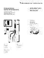
Einbauanleitung
Spezial-Versenkantenne
AUTA 4000 F 410 L
Zum Einbau in:
For installation in:
Pour montage sur:
Mercedes Benz
200 / 200 D / 230 E /
250 D / 260 E / 300 D / 300 E
Baureihe / Series / Série W 124
➝ 8.88
Bestell-Nr. / Ord. code / N° de cde.
920 772-001
Installation instructions
Special retractable car antenna
Instruction de montage
Antenne spéciale escamotable
Fig. 1
450 cm
31,5 cm
88 cm
➂
➀
➁
➃
50°
D
Lieferumfang
➀
Antenne
➁
Zubehör
➂
Halter
➃
HF-Kabel
GB
Scope of delivery
➀
Antenna
➁
Accessories
➂
Bracket
➃
RF-cable
F
Gamme de livraison
➀
Antenne
➁
Accessoires
➂
Support
➃
Câble H.F.

50°
blank
bare
non-traité
2
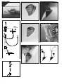
Fig. 3
Fig. 2
Fig. 4
Fig. 4
Fig. 5
Fig. 4
Fig. 6
Fig. 4
Fig. 7
Fig. 4
Fig. 8
Fig. 4
Fig. 9
Fig. 4
Fig. 10
495 750-305

3
D GB
Einbauanleitung
Der Einbau der Versenkantenne
AUTA 4000 F 410 L erfolgt bei den angegebenen
Mercedes-Benz-Modellen in den linken hinteren
Kotflügel.
Im Kofferraum die linksseitige Auskleidung
entfernen. Bei Wagen mit Anhängervorrich-
tung vorher die Strebe abschrauben. Für
Kabelverlegung hintere Sitzbank und -kissen
ausbauen.
An der Einbaustelle nach Fig. 1 bzw. 2 die
beiliegende Schablone anlegen, das Karosse-
rieloch anzeichnen und maßhaltig einarbeiten
(Toleranz ±0,2 mm). Zum Schutz des Lackes
vorher mit Klebeband abkleben. Die Bohrung
entgraten, zum Schutz gegen Korrosion die
blanke Kante mit Grundlack bestreichen und
trocknen lassen.
In der Zwischenzeit das Antennenkabel
zusammen mit dem bereits verlegten Lei-
tungssatz durch die Mehrfachtülle unter die
Rücksitzbank, von dort unter der linken Ein-
stiegsleiste, im Kabelkanal bis zum Fahrersitz
nach vorne und von dort zum Empfänger
verlegen und einstecken (evt. Durchziehdraht
verwenden).
Das Antennenkabel ist geräteseitig mit einem
abwinkelbaren Stecker versehen. Dadurch
kann der Stecker je nach Bedarf gerade oder
als Winkelstecker verwendet werden. Das
Abbiegen über den Führungsrücken bitte nur
von Hand durchführen, damit Kabel und
Stecker nicht verletzt werden (Fig. 3).
Die Dichttülle von oben in das Karosserieloch
einsetzen (Fig. 4 und 5). Dies muß am unteren
Einstich der Dichttülle erfolgen. Der obere
Einstich liegt gut sichtbar über der Karosserie
(Fig. 4 und 6).
Das Antennenkabel an der Antenne fest-
schrauben, den Kugelstutzen mit etwas
Antennenfett bestreichen (AUTA 115) und die
Antenne von unten in die bereits eingesetzte
Dichttülle eindrücken (Fig. 4).
Die Antenne mit Halter am Schutzrohr gegen
das vorhandene Langloch am Karosseriesteg
anschrauben (Fig. 3 und 9).
Teleskop ausziehen, Neigung kontrollieren;
danach Schrauben am Halter fest anziehen.
Die Kappe von oben auf die Dichttülle auf-
setzen, leicht nachdrücken, bis sie einrastet
und an der Karosserieoberfläche gleichmäßig
anliegt (Fig. 4, 7 und 8).
Das Masseband an vorhandenem Loch an
der Verstrebung festschrauben, Anlagefläche
vorher blank schaben und einfetten (Fig. 3
und 9).
Auskleidung im Kofferraum und Rücksitz wie-
der einbauen.
Das Teleskop ist mit einem Stülpknopf
(720 978-002) ausgerüstet (Fig. 3) und kann
von Hand gegriffen und ausgezogen werden.
Mit abgenommenem Stülpknopf kann das
Teleskop vollständig versenkt und nur mit
dem Schlüssel ausgezogen werden (Fig. 10).
Achten Sie bitte darauf, daß nach dem Einbau
der Antenne der Empfänger nachgetrimmt
wird. Am Antenneneingang des Gerätes ist ein
von außen bedienbarer Trimmer eingebaut.
Bei ganz ausgezogener Antenne einen
schwach einfallenden Sender im Mittelwellen-
bereich (ca.1100 kHz bzw. nach Angaben
Installation instructions
Installation of the retractable antenna
AUTA 4000 F 410 L left-side in the rear wing of
the stated Mercedes-Benz cars.
Remove left-side lining in the luggage-boot.
For cars with trailer coupling, unscrew pre-
viously the support. For cable laying detach
the back seat, too.
Apply the attached drilling template and mark
the installation point acc. to fig. 1 or 2, resp.,
cover the paintwork with protective tape, and
drill a hole (tolerance ±0,2 mm). Remove the
burr, spread the bare edge with primer to
protect against corrosion and allow to dry.
In the meantime pass the antenna cable
through the multiple grommet under the back
seat, then along the left edge in the cable
tunnel to the front and plug-in to the radio
receiver (if necessary use a draw wire).
At the radio end the antenna cable is fitted
with a plug that can be angled, so it can be
used straight or, if necessary, as an angled
plug. Please bend by hand only to avoid any
damage of cable or plug (fig. 3).
Insert the sealing sleeve from top into the car
body hole (fig. 4 and 5). Take care that the
lower recess of the sleeve fits to the body
sheet, so the upper recess should be clearly
visible above the car body (fig. 4 and 6).
Tighten the antenna cable to the antenna
case, spread the spherical antenna head with
some special grease (AUTA 115) and push
the antenna from below through the sleeve
inserted before (fig. 4).
Fix the antenna with bracket at the protective
tube to the existing oblong hole in the car
body bar (fig. 3 and 9).
Extend the telescope, check the angle, then
tighten the screws at the bracket.
Apply the cap on top of the sleeve and press
until snapping-on and fitting tightly to the car
body surface (fig. 4, 7 and 8).
Fix the earthing tape to the existing hole at
the brace. Previously bare the connecting
surface and spread with grease
(fig. 3 and 9).
Replace lining and back seat.
On top the telescope is provided with a plastic
knob (720 978-002) as shown in fig. 3, that
can be extended by hand. If this knob is de-
tached, the telescope can – after retraction –
only be extended by a special key (fig. 10).
Please make sure that the radio will be tuned
again after the antenna has been installed. On
the antenna input of the receiver there is an
incorporated trimmer that can be operated
from outside.
With antenna fully extended select a weak
station in the medium wave band (approx.
1100 kHz or acc. to the instructions of the
manufacturer of the radio) and set the maxi-
mum volume by means of the trimmer.
The lowest tube must be always fully exten-
ded in order to ensure a good reception.
From time to time, clean the telescope of adhe-
ring road dust. Use only a little of our special
aerial grease AUTA 235, supplied in tubes, or
our car aerial tissue AUTA 135 for both, cleaning
and greasing.
Instructions de montage
L'installation de l'antenne escamotable
AUTA 4000 F 410 L se fait dans les modèles
indiqués de Mercedes-Benz sur l'aile arrière
gauche.
Enlever le revêtement du côté gauche du
coffre. Seulement pour les véhicules pos-
sédant un dispositif pour remorque, dévisser
auparavant l'entretoise. Démonter la ban-
quette et coussin arrière pour la pose des
câbles.
A l'emplacement du montage, placer le
gabarit joint selon la fig. 1 resp. 2 marquer le
perçage de la carrosserie et percer selon les
dimensions prescriptes (tolérance ±0,2 mm).
Pour protéger la laque, coller auparavant un
ruban adhésif. Supprimer les bavures du
perçage, enduire le bord mis à nu de laque
de fond pour protéger contre la corrosion et
laisser sécher.
Entre-temps, poser le câble d'antenne avec
le jeu de câble déjà mis par le passe-câble
multiple sous la banquette arrière, de là, vers
l'avant sous le rebord d'accès gauche en
tunnel de câble jusque devant le siège du
conducteur et à partir de là, au récepteur et
enficher (au besoin utiliser du fil déroulable).
Le câble d'antenne est pourvu sur le côté de
l'appareil d'une connection à fiche pliable. De
ce fait, le connecteur peut être utilisé si
besoin est, droit ou comme fiche coudée.
Veuillez ne le tordre que manuellement par
dessus le tube conducteur, afin que câble et
fiche ne soit pas endommagés (fig. 3).
Placer la manchette d'en haut dans le perçage
de la carrosserie (fig. 4 et 5). Ceci doit être
effectué à l'encoche inférieure de la man-
chette. La fente supérieure est bien visible
au-dessus de la carrosserie (fig. 4 et 6).
Visser à fond le câble d'antenne à l'antenne,
enduire d'un peu de graisse le joint à bille
(AUTA 115) et appuyer l'antenne du dessous
dans la manchette déjà placée (fig. 4).
Visser l'antenne avec le support au tube contre
le trou longitudinal existant à la travers de car-
rosserie (fig. 3 et 9).
Sortir le télescope, contrôler l'inclinaison;
ensuite serrer à fond les vis au support.
Mettre le capuchon d'en haut sur la manchette,
appuyer légèrement, jusqu'à ce qu'il s'enclique-
tique et se trouve bien placé (fig. 4, 7 et 8).
Visser à fond la bande de mise à la masse
au perçage existant à l'entroise, gratter à nu
avant la surface et graisser (fig. 3 et 9).
Remettre le revêtement du coffre et la ban-
quette arrière.
Le télescope est équipé d'un bouton à
retournement (720 978-002) (fig. 3) et peut
être manipulé et sorti manuellement. Le téle-
scope peut être complètement noyé avec le
bouton à retournement enlevé et être seule-
ment sorti avec la clé (fig. 10).
Veuillez faire attention à ce que le récepteur
soit réadapté, après la pose de l'antenne.
A l'entrée de l'antenne de l'appareil, il est
monté un condensateur de compensation
réglable de l'extérieur.
Lorsque l'antenne est entièrement sorti, choisir
un émetteur reçu faiblement dans les ondes
moyennes (env. 1100 kHz resp. selon
données du constructeur) et régler à puis-
sance maximum.
F

024 549-000-08-0504-N
Printed in Europe . Imprimé en Europe
Please state order numbers when ordering
spare parts.
Right of modification reserved.
After its use, this product has to be processed
as electronique scrap to a proper disposal
according to the prevailing waste disposal regula-
tions of your community / district / country /
state.
The performance features described here are
binding only if they have been expressly guaran-
teed in the contract. This publication has been
created by Hirschmann Car Communication GmbH
according to the best of our knowledge.
Hirschmann reserves the right to change the
contents of this manual without prior notice.
Hirschmann can give no guarantee in respect of
the correctness or accuracy of the details in this
publication.
des Geräteherstellers) einstellen und mit dem
Antennentrimmer größte Lautstärke einstellen.
Das unterste Rohr der Antenne muß stets
vollständig ausgezogen werden. Nur so ist
ein einwandfreier Empfang gewährleistet.
Reinigen Sie Ihre Antenne von Zeit zu Zeit von
anhaftendem Straßenstaub. Verwenden Sie nur
ganz wenig von unserem Spezialfett in Tuben
AUTA 235, oder benutzen Sie unser Autoanten-
nen-Pflegetüchlein AUTA 135, das gleichzeitig
reinigt und fettet.
Ersatzteile bitte unter den angegebenen Num-
mern bestellen.
Technische Änderungen vorbehalten.
Dieses Produkt ist nach seiner Verwendung ent-
sprechend den aktuellen Entsorgungsvorschrif-
ten Ihres Landkreises / Landes / Staates als
Elektronikschrott einer geordneten Entsorgung
zuzuführen.
Die beschriebenen Leistungsmerkmale sind nur
dann verbindlich, wenn sie bei Vertragsabschluss
ausdrücklich vereinbart wurden. Diese Druckschrift
wurde von Hirschmann Car Communication GmbH
auf Übereinstimmung mit den beschriebenen
Antennen und Antennenzubehör (Kabel, Stecker
etc.) geprüft. Dennoch können Abweichungen
hinsichtlich der Richtigkeit oder Genauigkeit
nicht ausgeschlossen werden, sodass Hirsch-
mann für die vollständige Übereinstimmung
keine Gewähr übernimmt. Hirschmann behält
sich das Recht vor, den Inhalt dieser Druckschrift
ohne Ankündigung zu ändern.
Le tube le plus bas de l'antenne doit toujours
être sorti complètement. Seulement de cette
façon, il est possible d'avoir une réception
parfaite.
Débarrasser votre antenne des poussières
adhérentes de la rue, de temps en temps.
Utiliser très peu notre graisse spéciale sous
forme de tube AUTA 235, ou bien utiliser notre
essuie-antenne-auto AUTA 135 qui nettoie et
graisse en même temps.
Veuillez commander les pièces détachées sous
les numéros indiqués.
Sous réserve de modifications techniques.
Ce produit doit être éliminé en tant que déchet
électronique conformément au réglement actuel
sur l'élimination des déchets de votre départe-
ment / région / pays.
La société Hirschmann Car Communication GmbH
ne se porte garante de la véracité des informations
techniques que si elles ont été spécifiées de
manière expresse à la signature du contrat.
Le contenu de ce document a été minutieuse-
ment contrôlé afin de s’assurer qu’il corresponde
bien aux antennes et accessoires (câbles,
connecteurs) décrits. Toutefois, Hirschmann ne
peut en aucun cas être tenu responsable de
l’exactitude de ces informations. Hirschmann se
réserve le droit de modifier sans préavis le con-
tenu de ce document.
Hirschmann Car Communication GmbH
Stuttgarter Strasse 45 - 51
D-72654 Neckartenzlingen
Tel +49-7127-14-1873
Fax +49-7127-14-1428
-
 1
1
-
 2
2
-
 3
3
-
 4
4


Hirschmann Car Communication AUTA 4000 F 410 L Installationsanleitung
- Typ
- Installationsanleitung
in anderen Sprachen
Verwandte Artikel

Andere Dokumente
-
Hirschmann 920.446.001 Benutzerhandbuch
-
-
-
-
-
-
-
-
-
Blaupunkt LAS VEGAS DJ AG Bedienungsanleitung