
Effective May 2010 6D33996H02
05/10 AWA1230-2557
Front-mounted narrow terminal
kits on IZM low voltage
circuit breakers and cassettes
warning
(1) Only qualified electrical persOnnel shOuld
be permitted tO wOrk On the equipment.
(2) always de-energize primary and
secOndary circuits if a circuit breaker
cannOt be remOved tO a safe wOrk lOcatiOn.
(3) drawOut circuit breakers shOuld be
levered (racked) Out tO the discOnnect
pOsitiOn.
(4) all circuit breakers shOuld be switched
tO the Off pOsitiOn and mechanism springs
discharged.
failure tO fOllOw these steps fOr all
prOcedures described in this instructiOn
leaflet cOuld result in death, bOdily injury,
Or prOperty damage.
warning
the instructiOns cOntained in this awa and On
prOduct labels have tO be fOllOwed. Observe
the five safety rules:
– discOnnecting
– ensure that devices cannOt be
accidentally restarted
– verify isOlatiOn frOm the supply
– earthing and shOrt-circuiting
– cOvering Or prOviding barriers tO
adjacent live parts
discOnnect the equipment frOm the supply.
use Only authOrized spare parts in the repair
Of the equipment. the specified maintenance
intervals as well as the instructiOns fOr
repair and exchange must be strictly adhered
tO prevent injury tO persOnnel and damage tO
the switchbOard.
Section 1: General information
IZM20/IZM93 terminal block kits are available
for IZM20/IZM93 fix-mounted circuit breakers and
IZM20/IZM93 drawout cassettes.
Kits 2A10885G30 and G31 add front-mounted
terminals to three-pole IZM20/IZM93 breakers and
cassettes. G30 is used on 800–1250A units and
G31 on 1600–2000A.
Kits 2A10885G40 and G41 add front-mounted
terminals to four-pole IZM20/IZM93 breakers and
cassettes. G40 is used on 800–1250A units and
G41 on 1600–2000A.
Required tools
• 3/8-inch socket drive (with torque
measuring capability)
• 17 mm socket
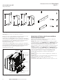
Kit parts identification
Refer to Figure 1 for visual identification of the
parts listed below for the different kits:
Kits #2A108850
(A) Line terminal: G30, G31 (three) and G40,
G41 (four)
(B) Load terminal: G30, G31 (three) and G40,
G41 (four)
(C) Line terminal: G31 (three) and G41 (four)
(D) Load terminal: G31 (three) and G41 (four)
(E) Spacer: G30, G31 (six) and G40, G41 (eight)
(F) Terminal bracket: G30, G31 (two)
(G) Terminal bracket: G40, G41 (two)
(H) M10 x 60 mm hex head bolt: G31 (six) and
G41 (eight)
(I) M10 x 45 mm hex head bolt: G30 (18), G31
(12), G40 (24) and G41 (16)
(J) M10 flat washer: G30, G31 (36) and G40,
G41 (48)
(K) M10 lock washer: G30, G31 (18) and G40,
G41 (24)
(L) M10 hex nut: G30, G31 (18) and G40, G41 (24)

2
Front-mounted narrow terminal
kits on IZM low voltage
circuit breakers and cassettes
EATON CORPORATION www.moeller.net/en/support
05/10 AWA1230-2557
Effective May 2010
Figure 1. Contents of Kits
ote:N Dimensions in millimeters
251.2
191.0
242.3
181.6
(A) (B) (C) (D)
(E)
(G)
(F)
(H)
(I)
(J)
(K)
(L)
Prior to installing a terminal kit, become familiar with the following
information and illustration (Figure 2).
Kits for 800–1250A breakers and cassettes contain one conductor
bar for each line and load conductor. The longer conductor bars
are to be fastened to the top of the line (upper) conductors. The
remaining (shorter) conductor bars are to be fastened to the bottom
of the load (lower) conductors.
Kits for 1600–2000A breakers and cassettes contain two
conductor bars for each line and load conductor. The longer
conductor bars are to be fastened to the top of the line (upper)
conductors. The remaining (shorter) conductor bars are to be
fastened to the bottom of the load (lower) conductors.
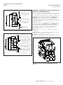
Figure 2. Typical Four-Pole IZM20/IZM93 Breaker
1.00 (25.4)
Hole Centers
Spacer
Hex Bolt
Lock Washer
Flat Washer
Terminal
Bracket
Lock Washer
Hex Bolt
Flat Washer
Hex Nut
Flat Washer
Section 2: Installation of front-mounted
terminal kit on fixed breaker
To install the terminal kit, refer to the appropriate illustration
associated with a specific kit, and proceed with the following
four steps:
Step 1: Fasten the load conductors to the breaker load terminals
using the hex bolts specified in the appropriate illustration with a
spherical lock washer under the bolt head, and flat washers against
the copper surfaces. Finger tighten only at this time.
Step 2: Fasten the terminal bracket across the load conductors
using the hex bolts specified in the appropriate illustration with a
spherical lock washer under the bolt head and flat washers against
the mounting surfaces. Be certain to place insulating spacers
between the terminal bracket and the load conductor. Torque the
hex bolts to 40 ft-lbs (52 Nm).
Step 3: Torque the hex bolts used in Step 1 to 40 ft-lbs (52 Nm).
Step 4: Fasten the line conductors to the breaker line conductors
by repeating Steps 1 through 3. This completes the line and
load connections.
ote:N The spacers (E) provided must be installed between the terminal
brackets (F) or (G) and the line and load conductors.

3
05/10 AWA1230-2557
Effective May 2010
Front-mounted narrow terminal
kits on IZM low voltage
circuit breakers and cassettes
EATON CORPORATION www.moeller.net/en/support
Figure 3. Steps 1–4: 2A10885G30 and G40 800–1250A
Figure 4. Steps 1–4: 2A10885G31 and G41 1600–2000A
Line Conductor (A)
Spacers (E) Between
All Terminal Brackets
(F) or (G)
M10 x 45 Hex Bolt (I) with
M10 Lock Washer (K),
Two M10 Flat Washers (J)
and M10 Hex Nut (L)
Load Conductor (B)
Line Conductor (C)
Spacers (E) Between
All Terminal Brackets
(F) or (G)
M10 x 45 Hex Bolt (I) with
M10 Lock Washer (K)
Two M10 Flat Washers (J)
and M10 Hex Nut (L)
Load Conductor (B)
Line Conductor (A)
Load Conductor (D)
M10 x 60 Hex Bolt (H) with
M10 Lock Washer (K),
Two M10 Flat Washers (J)
and M10 Hex Nut (L)
M10 x 60 Hex Bolt (H) with
M10 Lock Washer (K),
Two M10 Flat Washers (J)
and M10 Hex Nut (L)
Section 3: Installation of front-mounted
terminal kit on drawout cassette
To install the terminal kit, refer to the illustration provided. Also refer
to Section 2 copy and the first two associated graphics for exact
hardware identification and location for the specific ampere rating
of the cassette. Proceed with the following four steps:
Step 1: Fasten the load conductors to the cassette load terminals
using the hex bolts specified in the appropriate illustration with a
spherical lock washer under the bolt head, and flat washers against
the copper surfaces. Finger tighten only at this time.
Step 2: Fasten the terminal bracket across the load conductors
using the hex bolts specified in the appropriate illustration with a
spherical lock washer under the bolt head and flat washers against
the mounting surfaces. Be certain to place insulating spacers
between the terminal bracket and the load conductor. Torque the
hex bolts to 40 ft-lbs (52 Nm).
Step 3: Torque the hex bolts used in Step 1 to 40 ft-lbs (52 Nm).
Step 4: Fasten the line conductors to the cassette line conductors
by repeating Steps 1 through 3. This completes the line and load
connections.
ote:N The spacers (E) provided must be installed between the terminal
brackets (F) or (G) and the line and load conductors.
Figure 5. Steps 1–4: Typical Three-Pole IZM20/IZM93 Cassette

Front-mounted narrow terminal
kits on IZM low voltage
circuit breakers and cassettes
Eaton Industries GmbH
Electrical Sector
©2010 by Eaton Industries GmbH
Änderungen vorbehalten
Subject to alterations
05/10 AWA1230-2557 / Z8699
Moon/Doku/Heng
Printed in USA (05/10)
05/10 AWA1230-2557
Effective May 2010

Gültig ab Mai 2010 6D33996H02
05/10 AWA1230-2557
Frontanschlüsse für IZM20/IZM93
IZM-TF…
warnung
(1) Die instanDhaltung Darf nur Durch
entsprechenD elektrontechnisch
qualifiziertes personal erfolgen.
(2) Vor Beginn Der arBeiten muss Der
spannungsfreie zustanD Der schaltanlage
hergestellt unD währenD Der arBeiten
sichergestellt sein.
(3) schalter in ausfahrtechnik müssen
in trennstellung gefahren werDen.
(4) Die schalter sinD auf aus zu stellen
unD Der feDerspeicher ist zu entspannen.
Beim BetrieB elektrischer geräte stehen
zwangsläufig Bestimmte teile Dieser
geräte unter gefährlicher spannung.
unsachgemäßer umgang mit Diesen geräten
kann DeshalB zu toD oDer schweren
körperVerletzungen sowie erheBlichen
sachschäDen führen.
warnung
Beachten sie Bei instanDhaltungsmaßnahmen
an Diesem gerät alle in Dieser awa unD auf
Dem proDukt selBst aufgeführten hinweise.
Die fünf sicherheitsregeln sinD einzuhalten:
– freischalten
– gegen wieDereinschalten sichern
– spannungsfreiheit feststellen
– erDen unD kurzschließen
– BenachBarte, unter spannung stehenDe
teile aBDecken oDer aBschranken
Das gerät ist Vom netz zu trennen. es Dürfen
nur Vom hersteller zugelassene ersatzteile
VerwenDet werDen. Die VorgeschrieBenen
wartungsinterValle sowie Die anweisungen
für reparatur unD austausch sinD unBeDingt
einzuhalten, um schäDen an personen unD
anlagen zu VermeiDen.
Abschnitt 1: Allgemeine
Informationen
IZM20/IZM93-Frontanschlüsse sind für
Festeinbauschalter und Schalter in Ausfahrtechnik
verfügbar. Die Zubehörsätze 2A10885G30 und
G31 sind für 3-polige Schalter vorgesehen,
wobei G30 für 800–1250A Schalter und G31
für 1600–2000A Schalter geeignet sind.
Die Zubehörsätze 2A10885G40 und G41 sind
für 4-polige Schalter vorgesehen, wobei
G40 für 800–1250A Schalter und G41 für
1600–2000A Schalter geeignet sind.
Benötigtes Werkzeug
• 3/8 Zoll Drehmomentschlüssel
• 17mm Nuss
Inhalt (siehe Abbildung 1)
(A) Frontanschlüsse: G30, G31 (3x) und G40,
G41 (4x)
(B) Frontanschlüsse: G30, G31 (3x) und G40,
G41 (4x)
(C) Frontanschlüsse: G31 (3x) und G41 (4x)
(D) Frontanschlüsse: G31 (3x) und G41 (4x)
(E) Abstandsscheibe: G30, G31 (6x) und G40,
G41 (8X)
(F) Montagebrücke: G30, G31 (2x)
(G) Montagebrücke: G40, G41 (2x)
(H) Sechskantschraube M10 x 60: G31 (6x) und
G41 (8x)
(I) Sechskantschraube M10 x 45: G30 (18x), G31
(12x), G40 (24x) und G41 (16x)
(J) M10 Unterlegscheibe: G30, G31 (36x) und G40,
G41 (48x)
(K) M10 Federscheibe: G30, G31 (18x) und G40,
G41 (24x)
(L) M10 Sechskantmutter: G30, G31 (18x) und
G40, G41 (24x)

2
Frontanschlüsse für IZM20/IZM93
IZM-TF…
EATON CORPORATION www.moeller.net/de/support
05/10 AWA1230-2557
Gültig ab Mai 2010
Abbildung 1. Inhalt
nmerkung:A Abmessungen sind in Millimetern angegeben.
251.2
191.0
242.3
181.6
(A) (B) (C) (D)
(E)
(G)
(F)
(H)
(I)
(J)
(K)
(L)
Machen Sie sich vor der Installation der Frontanschlüsse mit den
Informationen und Abbildungen dieser AWA vertraut.
Zubehörsätze für 1600–2500A Schalter und Kassetten beinhalten
zwei Frontanschluss-Adapter für jede Anschlussleiste. Die längeren
Frontanschlüsse werden oberhalb der oberen Anschlussleisten
befestigt, die kürzeren werden unterhalb der unteren
Anschlussleisten befestigt.
Zubehörsätze für 1600–2500A Schalter und Kassetten beinhalten
zwei Frontanschluss-Adapter für jede Anschlussleiste. Die längeren
Frontanschlüsse werden oberhalb der oberen Anschlussleisten
befestigt, die kürzeren werden unterhalb der unteren
Anschlussleisten befestigt.
Abbildung 2. Beispiel: IZM20/IZM93 4-polig
1.00 (25.4)
Bohrabstand
Abstandsscheibe
Sechskantschraube
Federscheibe
Unterlagscheibe
Montagebrücke
Federscheibe
Sechskantschraube
Unterlagscheibe
Sechskantmutter
Unterlagscheibe
Abschnitt 2: Einbau der Frontanschlüsse
für Festeinbauschalter
Führen Sie die folgenden Schritte aus, beachten Sie dabei die
Anmerkungen der jeweiligen Abbildungen.
Schritt 1: Befestigen Sie die Frontanschlüsse mit den jeweiligen
Sechskantschrauben (siehe Abbildung 3 bzw. Abbildung 4) an den
Anschlussleisten der Abgangseite, mit jeweils einer Federscheibe
unter den Schraubenkopf und einer Unterlegscheibe auf der
Kupferoberfläche. Ziehen Sie die Schrauben nur mit den Fingern an.
Schritt 2: Schrauben Sie die Montagebrücke mit den jeweiligen
Sechskantschrauben (siehe Abbildung 3 bzw. Abbildung 4) an die
Frontanschlüsse der Abgangseite, mit jeweils einer Federscheibe
unter den Schraubenkopf und einer Unterlegscheibe auf der
Kupferoberfläche. Platzieren Sie dabei eine Abstandsscheibe
zwischen der Montagebrücke und den Frontanschlüssen.
(MA = 52 Nm).
Schritt 3: Ziehen Sie die in Schritt 1 angebrachten Schrauben an
(MA = 52 Nm).
Schritt 4: Bringen Sie die Frontanschlüsse an der Einspeisung an,
indem Sie für diese die Schritte 1–3 wiederholen.
nmerkung:A Die Abstandsscheiben (E) müssen zwischen den
Montagebrücken (F) oder (G) und den Anschlussleisten eingesetzt werden.

3
05/10 AWA1230-2557
Gültig ab Mai 2010
Frontanschlüsse für IZM20/IZM93
IZM-TF…
EATON CORPORATION www.moeller.net/de/support
Abbildung 3. Schritte 1–4: 2A10885G30 und G40 800–1250A
Abbildung 4. Schritte 1–4: 2A10885G31 und G41 1600–2000A
Frontanschluss (A),
Einspeisung
Abstandsscheiben (E)
zwischen Montagebrücke
(F) oder (G) und
Sammelschiene
Sechskantschraube
M10 x 45 mit einer M10
Federscheibe, zwei
M10 Unterlagsscheiben
und einer M10
Sechskantmutter
Frontanschluss (B),
Abgangsseite
Frontanschluss (C), Einspeisung
Abstandsscheiben (E)
zwischen Montagebrücke (F)
oder (G) und Sammelschiene
Sechskantschraube
M10 x 45 mit einer M10
Federscheibe, zwei M10
Unterlagsscheiben und einer
M10 Sechskantmutter
Frontanschluss (B),
Abgangsseite
Frontanschluss (A), Einspeisung
Frontanschluss (D),
Abgangsseite
Sechskantschraube
M10 x 60 mit einer M10
Federscheibe, zwei M10
Unterlagsscheiben und einer
M10 Sechskantmutter
Sechskantschraube
M10 x 60 mit einer M10
Federscheibe, zwei M10
Unterlagsscheiben und
einer M10 Sechskantmutter
Abschnitt 3: Einbau der Frontanschlüsse für
Schalter in Ausfahrtechnik
Führen Sie die folgenden Schritte aus, beachten Sie beim Einbau
auch die zu Abschnitt 2 gehörigen Abbildungen. Diese gelten auch
für den Einbau von Frontanschlüssen für Schalter in Ausfahrtechnik.
Schritt 1: Befestigen Sie die Frontanschlüsse für die Kassette
mit den jeweiligen Sechskantschrauben (siehe Abbildung 3 bzw.
Abbildung 4) an den Anschlussleisten der Abgangseite, mit
jeweils einer Federscheibe unter den Schraubenkopf und einer
Unterlegscheibe auf der Kupferoberfläche. Ziehen Sie die Schrauben
nur mit den Fingern an.
Schritt 2: Schrauben Sie die Montagebrücke mit den jeweiligen
Sechskantschrauben (siehe Abbildung 3 bzw. Abbildung 4) an die
Frontanschlüsse der Abgangseite, mit jeweils einer Federscheibe
unter den Schraubenkopf und einer Unterlegscheibe auf der
Kupferoberfläche. Platzieren Sie dabei eine Abstandsscheibe
zwischen der Montagebrücke und den Frontanschlüssen.
(MA = 52 Nm).
Schritt 3: Ziehen Sie die in Schritt 1 angebrachten Schrauben an
(MA = 52 Nm).
Schritt 4: Bringen Sie die Frontanschlüsse an der Einspeisung an,
indem Sie für diese die Schritte 1–3 wiederholen.
nmerkung:A Die Abstandsscheiben (E) müssen zwischen den
Montagebrücken (F) oder (G) und den Anschlussleisten eingesetzt werden.
Abbildung 5. Schritte 1–4: Beispiel IZM20/IZM93 Kassette
3-polig

Frontanschlüsse für IZM20/IZM93
IZM-TF…
Eaton Industries GmbH
Electrical Sector
©2010 by Eaton Industries GmbH
Änderungen vorbehalten
Subject to alterations
05/10 AWA1230-2557 / Z8699
Moon/Doku/Heng
Printed in USA (05/10)
05/10 AWA1230-2557
Gültig ab Mai 2010
-
 1
1
-
 2
2
-
 3
3
-
 4
4
-
 5
5
-
 6
6
-
 7
7
-
 8
8


