Tempo Communications OPM510 Benutzerhandbuch
- Kategorie
- Kabelnetzwerktester
- Typ
- Benutzerhandbuch

INSTRUCTION MANUAL
Read and understand all of the instructions and
safety information in this manual before operat-
ing or servicing this tool.
Register this product at www.TempoCom.com
52040482 REV16 © 2023 Tempo Communications Inc. 03/23
OPM510 • OPM520
Fiber Optic Power Meter
SLS520 • SLS530 • SLS535 • SLS536
Laser Source
SLS525
LED Source
English......1
Spanish...22
French.....43
German...64

2
KEEP THIS MANUAL
Table of Contents
Description ..................................................................................... 3
Safety ............................................................................................. 4
Purpose of This Manual ................................................................... 4
Important Safety Information ....................................................... 5–7
Introduction ................................................................................8–9
Model Designations ................................................................... 8
Unpacking and Inspection .......................................................... 9
Specications ......................................................................... 10–11
OPM ........................................................................................ 10
SLS ......................................................................................... 11
General Information ................................................................. 12–13
Auto-Shutoff Feature ................................................................ 12
Battery Installation or Replacement .......................................... 13
Snap-On Connector (SOC) Interface .......................................... 13
Operation ................................................................................ 14–15
OPM ........................................................................................ 14
SLS ......................................................................................... 15
Applications ..............................................................................16-20
One Test Jumper Method: Connector Loss ...........................16-17
Two Test Jumper Method: Link Loss ....................................18-20
Warranty ....................................................................................... 21

OPM510 • OPM520 • SLS520 • SLS525 • SLS530 • SLS535 • SLS536
3
Description
The Tempo Communications berTOOLS™ instruments are handheld
ber optic tools designed to measure optical power levels and link loss
on multi-mode and single-mode ber optic cabling networks.
• The OPM510 power meter measures optical power at 850 nm, 1300
nm, 1310 nm, 1490nm, 1550nm and 1625 nm between a power range of
+10 to -65dBm. The OPM510 is supplied standard with a SC bulkhead
adapter with LC, ST and FC adapters optionally available.
• The OPM520 power meter measures optical power at 850 nm, 1300
nm, 1310 nm, 1490nm, 1550nm and 1625 nm between a power range of
+27 to -50dBm. The OPM520 is supplied standard with a SC bulkhead
adapter with LC, ST and FC adapters optionally available.
• The SLS520 Laser source provides a light source at 1310nm and
1550nm to measure insertion loss on singlemode ber optic cabling.
The SLS520 is supplied standard with a SC bulkhead adapter with LC,
ST and FC adapters optionally available.
• The SLS525 LED source provides a light source at 850nm and 1300nm
to measure insertion loss on multimode ber optic cabling. The SLS525
is supplied standard with a SC bulkhead adapter with LC, ST and FC
adapters optionally available. The modal launch is not controlled.
• The SLS530 Laser source provides a light source at 1310nm, 1490nm
and 1550nm to measure insertion loss on singlemode ber optic
cabling. The SLS530 is supplied standard with a SC bulkhead adapter
with LC, ST and FC adapters optionally available.
• The SLS535 Laser source provides a light source at 1310nm, 1550nm
and 1625nm to measure insertion loss on singlemode ber optic
cabling. The SLS535 is supplied standard with a SC bulkhead adapter
with LC, ST and FC adapters optionally available.
• The SLS536 Laser source provides a light source at 1310nm, 1550nm
and 1650nm to measure insertion loss on singlemode ber optic
cabling. The SLS536 is supplied standard with a SC bulkhead adapter
with LC, ST and FC adapters optionally available.

4
Safety
Safety is essential in the use and maintenance of Tempo
Communications tools and equipment. This instruction manual and
any markings on the tool provide information for avoiding hazards
and unsafe practices related to the use of this tool. Observe all of the
safety information provided.
Purpose of This Manual
This instruction manual is intended to familiarize all personnel with
the safe operation and maintenance procedures for the Tempo
Communications OPM510, OPM520, SLS520, SLS525, SLS530, SLS535
and SLS536 berTOOLS instruments.

OPM510 • OPM520 • SLS520 • SLS525 • SLS530 • SLS535 • SLS536
5
SAFETY ALERT SYMBOL
This symbol is used to call your attention to hazards or unsafe
practices which could result in an injury or property damage. The
signal word, dened below, indicates the severity of the hazard.
The message after the signal word provides information for
preventing or avoiding the hazard.
Immediate hazards which, if not avoided, WILL result in severe
injury or death.
Hazards which, if not avoided, COULD result in severe injury or
death.
Hazards or unsafe practices which, if not avoided, MAY result in
injury or property damage.
Read and understand this material before operat-
ing or servicing this equipment. Failure to under-
stand how to safely operate this tool could result
in an accident causing serious injury or death.
Electric shock hazard:
Contact with live circuits could result in severe
injury or death.
Important Safety Information

6
The SLS520, SLS530, SLLS535 and SLS5336 instruments are a laser
device conforming to the requirements of CDRH, CFR 1040. While there
is no potential for eye damage due to unaided direct exposure, users
should always avoid looking directly into the output port. The use of
optical viewing instruments, such as microscopes, magniers, etc.,
should always be avoided. The use of such devices around active bers
can focus an intense beam of light energy onto the retina of the eye,
which can result in permanent damage.
Laser hazard:
• When performing measurements on ber optic systems, avoid eye
exposure to any open-ended bers, optical connectors, optical
interfaces, or other sources because they may be connected to
active laser transmitters.
• Do not look into the optical port when a source is turned on.
• Avoid looking at the free end of a test ber, i.e., the end not con-
nected to the instrument. If possible, direct the free end toward a
non-reective surface.
Failure to observe these precautions may result in injury.
Important Safety Information

OPM510 • OPM520 • SLS520 • SLS525 • SLS530 • SLS535 • SLS536
7
Electric shock hazard:
• Do not insert batteries with the polarity reversed.
• Do not open the case of the unit for any reason. It contains no
user-serviceable parts.
• Use this unit for the manufacturer’s intended purpose only, as
described in this manual. Any other use can impair the protection
provided by the unit.
Failure to observe these precautions may result in injury and may
damage the unit.
Instrument damage hazard:
• Do not leave the unit in direct sunlight or near direct sources of
heat.
• Protect the unit from strong impacts or shock.
• Do not immerse the unit in water or store in areas with high
humidity.
• When necessary, clean the case, front panel, and rubber cover with
a damp cloth. Do not use abrasives, harsh chemicals, or solvents.
• Replace the interface dust cap(s) when the unit is not in use.
• Store the unit and interface adapters in a cool, dry, and clean place.
Failure to observe these precautions may result in injury and may
damage the unit.
Important Safety Information

8
Introduction
Model Designations
The berTOOLS instruments incorporate different types of interfaces
and must be used with the compatible adapters.
berTOOLS Individual Instruments
OPM510 InGaAs Optical Power Meter
OPM520 InGaAs Optical Power Meter with high power
measurement range
SLS520 1310/1550nm Laser Source with SC connector
SLS525 850/1300nm LED Source with SC connector
SLS530 1310/1490/1550nm Laser Source with SC connector
SLS535 1310/1550/1625nm Laser Source with SC connector
SLS536 1310/1550/1650nm Laser Source with SC connector
berTOOLS Instruments Kits
SM DUAL KIT OPM510 & SLS520
SM DUAL KIT HP OPM520 & SLS520
MM DUAL KIT OPM510 & SLS525
SM T PON KIT OPM510 & SLS530
SM T 1625 KIT OPM510 & SLS535
SM T 1650 KIT OPM510 & SLS536
SM T PON KIT HP OPM520 & SLS530
SM T 1625 KIT HP OPM520 & SLS535
SM T 1650 KIT HP OPM520 & SLS536
SMMMKIT-T OPM510, SLS520 & SLS525
SMMMKIT-M OPM520, SLS520 & SLS525
Tempo Communications OPM Adapters
SC-OPM SC Adapter
LC-OPM LC Adapter
FC-OPM FC Adapter
ST-OPM ST Adapter

OPM510 • OPM520 • SLS520 • SLS525 • SLS530 • SLS535 • SLS536
9
Tempo Communications SLS Adapters
SC-Source SC/UPC Adapter
LC-Source LC/UPC Adapter
FC-Source FC/UPC Adapter
ST-Source ST/UPC Adapter
Tempo Communications Accessories
CC-1 Carry Case, Single Instrument
PS-100 External Power Supply
CC-2-3 Carry Case, Dual & Triple Instrument
Unpacking and Inspection
All berTOOLS instruments have been carefully inspected before
shipment. When received, the shipping carton should contain the items
listed below:
• 1 berTOOLS instrument
• 1 Soft Carry Case
• 1 Quick Reference Card
Please account for and inspect each item while unpacking and prepar-
ing the instrument for use.
If the instrument received is damaged, contact Tempo
Communications.
Keep the shipping carton in case re-shipment is required for any
reason.
Do not discard this product or throw away!
For recycling information, go to www.TempoCom.com.
All specications are nominal and may change as design improvements occur.
Tempo Communications Inc. shall not be liable for damages resulting from
misapplication or misuse of its products.
berTOOLS is a trademark of Tempo Communications Inc.
Do not discard this product or throw away!
For recycling information, go to www.TempoCom.com.

10
Specications
(1) The lower limit of 850nm measurement is -60 dBm for OPM510.
Specications subject to change without notice.
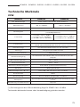
OPM
MODEL OPM510 OPM520
Cal. Wavelength 850, 1300, 1310, 1490, 1550,1625nm
Measure range -65 ~ +10(1)dBm -50 ~ +27dBm
Detector type InGaAs
Accuracy ±0.25 dB
(±0.5dB@850nm)
Linearity
+/-0.5dB (+10 to -3dBm)
+/-0.1dB (-3 to -50dBm)
+/-0.5dB (-50 to -65dBm)
+/-0.5dB (+27 to -3dBm)
+/-0.1dB (-3 to -50dBm)
Resolution (dB) 0.01dB
Functions µW/dBm/dB(REF)/ MOD tone detection
270Hz, 1kHz, 2kHz
Connector Type SC (Interchangeable LC, FC and ST)
Fiber Type Singlemode & Multimode
Battery Life > 100 hours
Power Supply 9V Alkaline or 1000mAh Lithium Battery / 9V AC
adapter
Operating Temperature -10°C ~ 50°C
Storage Temperature -20°C ~ 70°C
Relative Humidity 0 to 95% (non-condensing)
Weight 0.68lbs (310g)
Dimensions (H × W × T) 6.1 × 3.5 × 1.3” (155 × 88 × 33mm)
IP Rating IP54
Vibration 5Hz to 150Hz, Amplitude = 0.15mm
Shock Peak acceleration 25g at a pulse duration of 6ms
Compliance CE, FCC

OPM510 • OPM520 • SLS520 • SLS525 • SLS530 • SLS535 • SLS536
11
Model SLS520 SLS525 SLS530
Wavelength (±20nm) 1310/1550 850/1300 1310/1550/1625 1310/1550/1650
1310/1490/1550
Range of Use Singlemode Multimode Singlemode
Emitter Type FP LED FP
Spectral Width ≤ 5 nm +/-40 nm ≤ 5 nm
Output Power
Typical /Minimum 0dBm/-1dBm -20dBm/-21dBm 0dBm/-1dBm
Output Power Stability ±0.05 dB/15min
±0.15dB/8hr
±0.05 dB/15min;
±0.10dB/8hr
Modulation Frequency 270Hz, 1kHz, 2kHz
Display LCD
Battery Life 25 hours
Connector Type SC/PC (Interchangeable LC, ST, SC)
Power Supply 9V Alkaline or 1000mAh Lithium Battery / 9V AC adapter
Operating Temperature -10 to +50 ℃
Storage Temperature (℃) -20 to +70 ℃
Relative Humidity 0 to 95% (non-condensing)
Weight 0.71 lbs (320g)
Dimension (H×W×T) 6.1 × 3.5 × 1.3” (155 × 88 × 33mm)
IP Rating IP54
Vibration 5Hz to 150Hz, Amplitude = 0.15mm
Shock Peak acceleration 25g at a pulse duration of 6ms
Compliance CE, FCC, RoHS, 21 CFR 1040.10 (laser)
SLS535 SLS536
±0.05 dB/15min
±0.10dB/8hr
Specications
SLS
Specications subject to change without notice.
MODEL SLS520 SLS525 SLS530 SLS535 SLS536
Center Wavelength 1310/1550nm 850/1300nm
1310/
1490/
1550nm
1310/
1550/
1625nm
1310/
1550/
1650nm
Fiber Type Singlemode Multimode
(62.5/125) Singlemode
Emitter Type FP LED FP
Spectrum Width ≤ 5 nm
≤ 71nm
(850nm),
≤ 160nm
(1300nm)
≤ 5 nm
Output Power
(Max/Min)
0dBm/
-1dBm
-20dBm/
-21dBm 0dBm/-1dBm
Output Power Stability
±0.05
dB/15min;
±0.10dB/8hr
±0.05
dB/15min;
±0.15dB/8hr
±0.05 dB/15min;
±0.10dB/8hr
Modulation Frequency 270Hz, 1kHz, 2kHz
Display LCD
Battery Life 60 hours
Connector Type SC/PC (Interchangeable LC, ST, SC)
Power Supply 9V Alkaline or 1000mAh Lithium Battery / 9V AC adapter
Operating Temperature -10 to +50°C
Storage Temperature -20 to +70°C
Relative Humidity 0 to 95% (non-condensing)
Weight 0.71 lbs (320g)
Dimensions (H × W × T) 6.1 × 3.5 × 1.3” (155 × 88 × 33mm)
IP Rating IP54
Vibration 5Hz to 150Hz, Amplitude = 0.15mm
Shock Peak acceleration 25g at a pulse duration of 6ms
Compliance CE, FCC, 21 CFR 1040.10 (laser)

12
General Information
This section provides general instructions on how to use the ber-
TOOLS instruments.
If circumstances require that the instruments be serviced and
maintained in-house, contact Tempo Communications for technical
assistance.
Battery
The OPM510, OPM520, SLS520, SLS525, SLS530, SLS535 and SLS536
instruments are powered by one 9V alkaline battery or one 9V Lithium
battery.
The optional external power supply can be used to power the OPM and
SLS rather than an alkaline battery. The external power supply is not
used to charge any rechargeable battery that may be installed in the
OPM or SLS.
Do not attempt to charge alkaline batteries with the external power
supply.
The battery level icon will ash alerting the user when the battery needs
to be replaced.
Auto Power Off.
The instrument will automatically turn off if there are no keypad pushes
for approximately ve minutes.
To deactivate or activate the auto power off, momentarily push the
[On/Off]. The Auto Off indicator will toggle.

OPM510 • OPM520 • SLS520 • SLS525 • SLS530 • SLS535 • SLS536
13
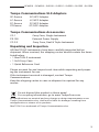
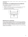
Battery Installation or Replacement
To replace the batteries, follow these steps:
1. Turn instrument off.
2. Remove battery cover by sliding down.
3. Install new battery to the wire leads observing correct polarity.
4. Slide battery cover back on.
Connector Interface
All berTOOLS OPM and SLS units utilize a screw on adapter for SC,
LC, FC and ST congurations. The OPM and SLS instrument bulkheads
are unique in that the adapters for the OPM are different from the SLS.
Do not attempt to use a OPM adapter on a SLS or vice versa. Please
consult the accessories section of this instruction manual for adapter
part numbers.
Battery Installation or Replacement (cont’d)
To replace the batteries, follow these steps:
1.
Turn instrument off.
2.
Remove battery cover by sliding down.
3.
Install new battery to the wire leads observing correct polarity.
14

14
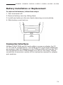
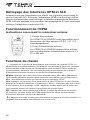
Cleaning the OPM and SLS Interfaces
Make sure that the instrument is powered off. Do not look into the
output of any SLS port. Unscrew the OPM adapter and use a clean lint
fee wipe to clean the exposed OPM detector window. Always use a new
2.5mm cleaning swab to clean the SLS bulkhead.
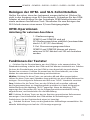
OPM Operations
External Connector Instruction
1. Fiber Optic Input
OPM510 & OPM520 is available with SC ber
optic connector (Interchangeable LC/ST/FC).
2. Ext. Power Jack
OPM510 & OPM520 can be operated with an
External Power Adapter 9V DC@250mA.
Keypad Functions
: Push the power button to turn the OPM on or off. The default setting will turn
the OPM off after ve minutes of inactivity. Momentarily push the power button to
place the OPM into a constant on mode. Momentarily pushing the power button
again will revert to the auto off mode.
dB/dBm: Press this key to toggle between dB and dBm. Hold this key for two
seconds to set a 0dBm reference. A successful reference is annotated by a
“HELD” message.
Zero: Press the Zero key to zero the OPM with the input port protected
from ambient light. A message of “SUCC” will be displayed upon
successful zeroing. If an “ERR” message appears check that
the input port was in fact covered properly and repeat the zeroing
procedure.
REF: Press this key to display the reference value stored in memory. Zeroing the
OPM will remove the effects of any dark current inherent to the detector diode.
: Press this key to select the desired wavelength. The current wavelength will
be displayed on LCD.
OPM5XX Optical Power Meter Quick Reference
External Connector Instruction
①① Fiber Optic Input
OPM510 & OPM520 is available with SC fiber optic connector
(Interchangeable LC/ST/FC).
②② Ext. AC Power Jack
OPM510 & OPM520 can be operated with an External Power Adapter 9V
DC@250mA.
Keypad Functions
【【】】Push the power button to turn the OPM on or off. The default setting will
turn the OPM off after five minutes of inactivity. Hold the power button for two
seconds to place the OPM into a constant on mode. Holding the power button
again for two seconds will revert to the auto off mode.
【【dB/dBm】】 Press this key to switch the measurement mode between absolute
power (dBm) and relative loss (dB). Hold the key until "HELD" is displayed.
【【Zero】】Press the Zero key to zero the OPM with the input port protected from
ambient light. A message of “SUCC” will be displayed upon successful zeroing. If
an “ERR” message appears check that the input port was in fact covered properly
and repeat the zeroing procedure.
【【Ref】】Press this key to display the reference value stored in memory. Hold the
key down until "HELD" appears in the display. When the OPM is switched to dB
mode, the LCD displays the difference in dB between the reference level and the
current input signal.
【【λ】】Press this key to select the wavelength to be measured.
The External Power LED Indicator will illuminate when the unit is powered by the
external power supply.

OPM510 • OPM520 • SLS520 • SLS525 • SLS530 • SLS535 • SLS536
15
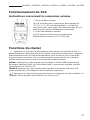
SLS Operations
External Connector Instruction
1. Fiber Optic Output
SLS supplied with SC/PC ber optic connector
(intechangeable LC/FC/ST). This is a at polished
connector; do not connect angle polished connectors
to the bulkhead.
2. Ext. Power Jack
SLS can be operated with an External Power Adapter
9V DC@250mA.
Keypad Functions
: Push the power button to turn the SLS on or off. The default setting will turn
the SLS off after ve minutes of inactivity. Momentarily push the power button to
place the SLS into a constant on mode. Momentarily pushing the power button
again will revert to the auto off mode.
μW/Bm: Press this key to switch the display mode from absolute power (dBm) to
microwatt(μW). The current optical power will be displayed on LCD.
CW/Mod: Press this key to switch the output of SLS from CW to the desired
modulation frequency.
: Press this key to select the desired wavelength. The current wavelength will
be displayed on LCD.
OPM5XX Optical Power Meter Quick Reference
External Connector Instruction
①① Fiber Optic Input
OPM510 & OPM520 is available with SC fiber optic connector
(Interchangeable LC/ST/FC).
②② Ext. AC Power Jack
OPM510 & OPM520 can be operated with an External Power Adapter 9V
DC@250mA.
Keypad Functions
【【】】Push the power button to turn the OPM on or off. The default setting will
turn the OPM off after five minutes of inactivity. Hold the power button for two
seconds to place the OPM into a constant on mode. Holding the power button
again for two seconds will revert to the auto off mode.
【【dB/dBm】】 Press this key to switch the measurement mode between absolute
power (dBm) and relative loss (dB). Hold the key until "HELD" is displayed.
【【Zero】】Press the Zero key to zero the OPM with the input port protected from
ambient light. A message of “SUCC” will be displayed upon successful zeroing. If
an “ERR” message appears check that the input port was in fact covered properly
and repeat the zeroing procedure.
【【Ref】】Press this key to display the reference value stored in memory. Hold the
key down until "HELD" appears in the display. When the OPM is switched to dB
mode, the LCD displays the difference in dB between the reference level and the
current input signal.
【【λ】】Press this key to select the wavelength to be measured.
The External Power LED Indicator will illuminate when the unit is powered by the
external power supply.

16
Applications
The following applications for the berTOOLS instruments are
described in this manual:
• Connector/cable insertion loss measurements
• Link loss measurements
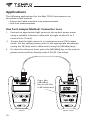
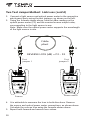
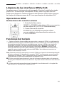
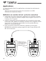
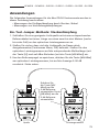
One Test Jumper Method: Connector Loss
1. Connect an appropriate light source to the optical power meter
using a suitable reference cable with a length of about 2 to 3
meters (6 to 10 feet).
2. Ensure that the light source is in continuous wave (CW) output
mode. Set the optical power meter to the appropriate wavelength
(using the [ ] key) and to dBm units (using the [dB/dBm] key).
3. To store the reference level, press the [dB/dBm] key on the optical
power meter until the display reads 0.00 dB. See below.
OPM5XX Optical Power Meter Quick Reference
External Connector Instruction
①① Fiber Optic Input
OPM510 & OPM520 is available with SC fiber optic connector
(Interchangeable LC/ST/FC).
②② Ext. AC Power Jack
OPM510 & OPM520 can be operated with an External Power Adapter 9V
DC@250mA.
Keypad Functions
【【】】Push the power button to turn the OPM on or off. The default setting will
turn the OPM off after five minutes of inactivity. Hold the power button for two
seconds to place the OPM into a constant on mode. Holding the power button
again for two seconds will revert to the auto off mode.
【【dB/dBm】】 Press this key to switch the measurement mode between absolute
power (dBm) and relative loss (dB). Hold the key until "HELD" is displayed.
【【Zero】】Press the Zero key to zero the OPM with the input port protected from
ambient light. A message of “SUCC” will be displayed upon successful zeroing. If
an “ERR” message appears check that the input port was in fact covered properly
and repeat the zeroing procedure.
【【Ref】】Press this key to display the reference value stored in memory. Hold the
key down until "HELD" appears in the display. When the OPM is switched to dB
mode, the LCD displays the difference in dB between the reference level and the
current input signal.
【【λ】】Press this key to select the wavelength to be measured.
The External Power LED Indicator will illuminate when the unit is powered by the
external power supply.
Press the
[dB/dBm]
key to set the
0 dB reference
Source Power meter

OPM510 • OPM520 • SLS520 • SLS525 • SLS530 • SLS535 • SLS536
17
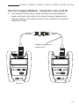
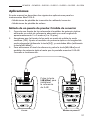
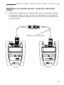
One Test Jumper Method: Connector Loss (cont’d)
4. Disconnect the reference cable end from the optical power
meter and insert the cable to be tested using an appropriate
mating adapter. The optical power meter reads the connector/
cable loss in dB.
Cable/connector
under test
Source Power meter

18
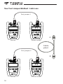
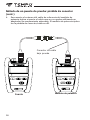
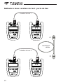
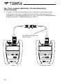
Two Test Jumper Method: Link Loss
Cable
plant
A
B
Test jumper 1
P1
Source Power meter
Test jumper 2
P2
Source Power meter

OPM510 • OPM520 • SLS520 • SLS525 • SLS530 • SLS535 • SLS536
19
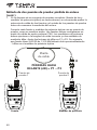
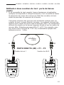
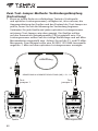
Two Test Jumper Method: Link Loss (cont’d)
1. If a complete test set (light source and optical power meter) is
available at each end, it is advisable to test the output power of
the sources and the condition of the test jumpers before
commencing measurement of the link.
Connect each source and optical power meter with a test jumper,
as shown above. The sources should be set to continuous wave
(CW) output mode. The power meters should be set to the correct
wavelength and to dBm measurement units. Note the P1 and P2
dBm readings. For example, a SLS520 1310 NM laser source
should read approximately -1dBm on the optical power meter.
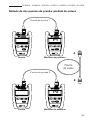
P3
Source Power meter
Test
jumper 1
Test
jumper 2
A B
Cable
plant
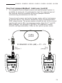
FORWARD LOSS (dB) = P1 – P3

20
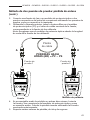
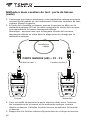
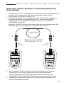
Two Test Jumper Method: Link Loss (cont’d)
2. Connect a light source and optical power meter to the respective
patch panel ports using the test jumpers, as shown on the left.
3. Using the formula shown above, take the dBm reading on the
optical power meter (P3) and the nominal source output value,
corresponding to the light source in use.
Note: Make sure the optical power meter supports the wavelength
of the light source in use.
4. It is advisable to measure the loss in both directions. Reverse
the source and optical power meter connections, as shown above.
Calculate the reverse loss using the formula shown above.
5. Report both forward and reverse loss values.
Source
P4
Power meter
Test
jumper 1
Test
jumper 2
A B
Cable
plant
REVERSE LOSS (dB) = P2 – P4
Seite laden ...
Seite laden ...
Seite laden ...
Seite laden ...
Seite laden ...
Seite laden ...
Seite laden ...
Seite laden ...
Seite laden ...
Seite laden ...
Seite laden ...
Seite laden ...
Seite laden ...
Seite laden ...
Seite laden ...
Seite laden ...
Seite laden ...
Seite laden ...
Seite laden ...
Seite laden ...
Seite laden ...
Seite laden ...
Seite laden ...
Seite laden ...
Seite laden ...
Seite laden ...
Seite laden ...
Seite laden ...
Seite laden ...
Seite laden ...
Seite laden ...
Seite laden ...
Seite laden ...
Seite laden ...
Seite laden ...
Seite laden ...
Seite laden ...
Seite laden ...
Seite laden ...
Seite laden ...
Seite laden ...
Seite laden ...
Seite laden ...
Seite laden ...
Seite laden ...
Seite laden ...
Seite laden ...
Seite laden ...
Seite laden ...
Seite laden ...
Seite laden ...
Seite laden ...
Seite laden ...
Seite laden ...
Seite laden ...
Seite laden ...
Seite laden ...
Seite laden ...
Seite laden ...
Seite laden ...
Seite laden ...
Seite laden ...
Seite laden ...
Seite laden ...
-
 1
1
-
 2
2
-
 3
3
-
 4
4
-
 5
5
-
 6
6
-
 7
7
-
 8
8
-
 9
9
-
 10
10
-
 11
11
-
 12
12
-
 13
13
-
 14
14
-
 15
15
-
 16
16
-
 17
17
-
 18
18
-
 19
19
-
 20
20
-
 21
21
-
 22
22
-
 23
23
-
 24
24
-
 25
25
-
 26
26
-
 27
27
-
 28
28
-
 29
29
-
 30
30
-
 31
31
-
 32
32
-
 33
33
-
 34
34
-
 35
35
-
 36
36
-
 37
37
-
 38
38
-
 39
39
-
 40
40
-
 41
41
-
 42
42
-
 43
43
-
 44
44
-
 45
45
-
 46
46
-
 47
47
-
 48
48
-
 49
49
-
 50
50
-
 51
51
-
 52
52
-
 53
53
-
 54
54
-
 55
55
-
 56
56
-
 57
57
-
 58
58
-
 59
59
-
 60
60
-
 61
61
-
 62
62
-
 63
63
-
 64
64
-
 65
65
-
 66
66
-
 67
67
-
 68
68
-
 69
69
-
 70
70
-
 71
71
-
 72
72
-
 73
73
-
 74
74
-
 75
75
-
 76
76
-
 77
77
-
 78
78
-
 79
79
-
 80
80
-
 81
81
-
 82
82
-
 83
83
-
 84
84


Tempo Communications OPM510 Benutzerhandbuch
- Kategorie
- Kabelnetzwerktester
- Typ
- Benutzerhandbuch
in anderen Sprachen
Verwandte Papiere
Sonstige Unterlagen
-
Greenlee 560XL/567XL/568XL/570XL/573XL/577XL/578XL/580XL Benutzerhandbuch
-
-
 Triotronik PRETERM 8E09 E2/APC-E2/APC 10.0M Benutzerhandbuch
-
Televes CATV optical transmitter Schnellstartanleitung
-
 Triotronik LKUP FC-SC MM Datenblatt
-
Tektronix P6703B Instructions Manual
-
POLYTRON OPM-LNB 064 Bedienungsanleitung
-
Trendnet TE100S24G Benutzerhandbuch
-
FS Fotr Series Handheld Optical Time Domain Reflectometer Benutzerhandbuch

