
Güterwagen
Dampok • Steam locomotive
Locomotive à vapeur • Parní lokomotiva
Parowóz BR 50.40
www.tillig.com www.facebook.com/tilligbahn 364386 / 18.07.2023
112
Art.-Nr. / Item no. / Réf. / Art.-č. / Nr art.
03030 03031 03032 03033
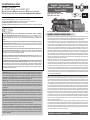
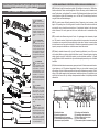
Das Modell ist eine maßstäbliche Nachbildung mit authentischer Lackierung und Dekoration. Eine hohe Detailtreue wird durch die
Ausführung der Heusingersteuerung aus Kunststo und die Verkleinerung der Radreifenprole erreicht. Die Räder sind 2,2 mm breit und
haben eine Spurkranzhöhe von 0,9 mm. Damit setzt das Modell entsprechend hohe Anforderungen an die Gleisverlegung.
Optimale Fahreigenschaften werden auf sauber verlegten TILLIG-TT-Modellgleisen erreicht. Das Standardgleis ist wegen sei-
ner großen Toleranzen nicht geeignet. Wird das Modell auf Standardgleisen eingesetzt, dürfen Weichen nur langsam befahren
werden. Die Weichen müssen in einwandfreiem Zustand sein, sonst läuft der Vorläufer auf die “Herzstückspitze” auf. Die Steue-
rungsteile besitzen eine größere Elastizität als geätzte Teile aus Metall, sollten aber dennoch nicht unnötig belastet werden. Die
Beleuchtung an Lok und Tender wechselt automatisch mit der Fahrtrichtung. An beiden Fahrzeugenden bendet sich eine Kurz-
kupplung mit einer Kupplungsaufnahme nach NEM 355. Der Antrieb des Modells erfolgt über alle Radsätze des Tenders. Der vor-
letzte Radsatz ist mit Haftreifen versehen. Alle Tenderradsätze sowie der erste und vierte Kuppelradsatz der Lok dienen der Strom-
aufnahme. Der Tenderantrieb ist werkseitig ausreichend gefettet. Ein Nachfetten sollte erst nach ca. 50-100 Betriebsstunden mit
säure- und harzfreiem Fett (technische Vaseline) erfolgen. Zum Önen des Tenders ist die hintere Puerbohle des Tenders abzu-
ziehen. Dazu werden die Puer leicht (!) nach innen gedrückt, so dass die seitlichen Rastnasen aus dem Fahrgestell ausrasten. Dann wird die
Puerbohle nach hinten gezogen. Dann wird der Auftritt an der Vorderseite des Tenders und der Werkzeugkasten an der Hinterseite abge-
zogen. Danach kann das Tenderoberteil abgenommen werden.
Die Einzelteile des Tenders verlieren bei dieser Demontage ihren Halt und können abfallen oder nicht mehr in der
richtigen Lage sein. Bei der Montage in umgekehrter Reihenfolge ist beim Aufrasten der Puerbohle auf die Lage der seitlichen Lei-
tungsnachbildungen zu achten. Diese Leitungen müssen über die Puerbohlenseitenwände gelegt werden. Vor einer Demontage der
Lok wird dringend abgeraten! Bei Beschädigung des Siegellackes erlischt der Garantieanspruch. Zur weiteren optischen Aufwertung
des Modells sind einige Zurüstteile beigelegt. Alle Teile sollten mit etwas Klebsto xiert werden. Die Anbringung der Zurüstteile geht
aus den Abbildungen hervor. Die Befestigung der Bremsschläuche ist nur möglich, wenn Radien größer als 350 mm befahren werden
oder auf eine Kupplung an dieser Seite verzichtet wird. Die Verwendung der Kolbenstangenschutzrohre ist erst bei Radien oberhalb
von 350 mm möglich. Das Kuppeln von Lok und Tender ist auf einem geraden Gleisabschnitt durch Zusammenschieben beider Fahr-
zeuge auf dem Gleis vorzunehmen. Zuvor ist darauf zu achten, dass die Kupplungsdeichsel des Tenders in Mittelstellung steht (Blick
von vorn in den Schlitz des Kuppelkastens).
(GB) The model is a true-to-scale reproduction with authentic paint and decoration. Meticulous attention to detail is achieved by the
Walschaerts valve gear made of plastic and miniature tyre proles. The wheels are 2.2 mm wide with a wheel ange height of 0.9 mm.
The model thus places high demands on tracklaying. The best driving characteristics are achieved on neatly routed TILLIG-TT track
systems. The standard track is not suitable due to its large tolerances. Yet, if standard tracks are used, the model should drive slowly
over the point blades. The points must be in perfect condition; otherwise the pusher axle runs onto the “tip of the frog”. The control parts
feature greater elasticity than etched metal parts, however, unnecessary strain should be avoided. The lights of locomotive and tender
are changing automatically with the direction of travel. Both vehicles have a NEM 355 close coupler with coupler pocket. The model is
driven by all wheel sets of the tender. The second last wheel set is furnished with traction tyres. All tender wheel sets including the rst
and fourth coupling wheel sets of the locomotive are used to collect current. The tender drive comes adequately greased at delivery.
After approx. 50-100 operating hours regreasing should take place using acid-free and resin-free grease (technical vaseline). To open
the tender, you need to remove the rear buer beam of the tender. To do this carefully (!) press the buers inwards so that the side locking
tabs disengage from the running gear. Then pull the buer beam back. After this, remove the step on the front side of the tender and the
tool box located at the rear. The top of the tender can then be removed. during disassembly individual parts of the tender
may become loose and fall o or be moved out of position. When assembling in the reverse sequence, pay attention to the position of the
lateral running lines when locking the buer beam in place. These lines must be routed over the buer beam side walls. You are strongly
advised not to disassemble the locomotive!
All warranty claims expire immediately if the sealant is damaged. Several add-on parts have been included in the kit to improve the look
of the model. All these parts should be secured using a small amount of adhesive. The position of the add-on parts is show in the pictures.
It is only possible to secure the brake lines on track radii larger than 350 mm or if a coupling is dispensed with on this side. The piston rod
protection tubes can only be used on radii greater than 350 mm. Coupling locomotive and tender. This is to be undertaken on a straight
piece of track by pushing both vehicles together on the track. Before doing this, make sure that the coupling drawbar of the tender is in its
central position (viewed from the front in the slot of the coupling box.
When this product comes to the end of its useful life, you may not dispose of it in the ordinary
domestic waste but must take it to your local collection point for recycling electrical and electronic equipment. If you don’t know the location of
your nearest disposal centre please ask your retailer or the local council oce.
Tento produkt nesmí být na konci
svého užívání zlikvidován jako běžný domovní odpad, ale musí být zlikvidován např. ve sběrném dvoře. Prosím, zeptejte se vašeho obchodníka,
popř. na svém obecním úřadě o vhodném způsobu likvidace.
Produkty oznaczone przekreślonym pojemnikiem
po zakończeniu użytkowania nie mogą być usuwane razem z normalnymi odpadami domowymi, lecz muszą być przekazywane do punktu zbie-
rania i recyklingu urządzeń elektrycznych i elektronicznych. Dzięki recyklingowi pomagają Państwo skutecznie chronić środowisko naturalne.
Prosimy zwrócić się do specjalistycznego sklepu lub do odpowiedniego urzędu w Państwa okolicy, aby dowiedzieć się, gdzie jest najbliższy punkt
recyklingu urządzeń elektrycznych i elektronicznych.
À la n de sa durée de vie, ne pas éliminer ce produit avec les déchets ménagers
mais le remettre à un point de collecte pour le recyclage d’appareils électriques et électroniques. Veuillez vous adresser à votre revendeur ou à
l’administration communale pour connaître les points d’élimination compétents.
Dieses Produkt darf am Ende seiner Nutzungsdauer nicht über
den normalen Hausmüll entsorgt werden, sondern muss an einem Sammelpunkt für das Recycling von elektrischen und elek-
tronischen Geräten abgegeben werden. Bitte fragen Sie bei Ihrem Händler oder der Gemeindeverwaltung nach der zuständigen Entsor-
gungsstelle.
(DE) Technische Änderungen vorbehalten! Bei Reklamationen wenden Sie sich bitte an Ihren Fachhändler.
(GB) Subject to technical changes! Please contact your dealer if you have any complaints.
(FR) Sous réserve de modications techniques! Pour toute réclamation, adressez-vous à votre revendeur.
(CZ) Technické změny vyhrazeny! Při reklamaci se obraťte na svého obchodníka.
(PL) Zastrzega się możliwość zmian technicznych! W przypadku reklamacji prosimy zgłaszać się do specjalistycznego sprzedawcy.
Promenade 1, 01855 Sebnitz
Tel.: +49 (0)35971 / 903-45 • Fax: +49 (0)35971 / 903-19
(DE) Hotline Kundendienst • Hotline customer service • (FR) Services à la clientèle Hotline
(CZ) Hotline Zákaznické služby • Biuro Obsługi Klienta:
(DE) Für dieses TILLIG-Produkt gilt der gesetzliche Gewährleistungsanspruch von 24 Monaten ab
Kaufdatum. Dieser Gewährleistungsanspruch erlischt, wenn kundenseitige Eingrie, Veränderungen, Umbauten usw.
an dem Produkt erfolgen/vorgenommen werden. Bei Fahrzeugen mit eingebauter Schnittstelle, können Gewährleis-
tungsansprüche nur geltend gemacht werden, wenn das betreende Fahrzeug im Lieferzustand (ohne eingebautem
Digitaldecoder, mit eingestecktem Entstörsatz) an den Fachhändler zurück gegeben wird.
This TILLIG product is subject to the statutory warranty entitlement of 24 months from the date of
purchase. This warranty claim expires if the product is interfered with, modied or converted after the point of time of the
customer acquiring ownership. Where vehicles have an integrated interface, claims for warranty can only be asserted if
the vehicle concerned is returned in an as-delivered state (without built-in digital decoder, with plugged-in interference
suppression kit).
Pour ce produit TILLIG, le droit de garantie légal de 24 mois à partir de la date d’achat s’applique. Ce
droit de garantie s’éteint si le client procède/a procédé à des interventions, des modications, des transformations, etc.
sur le produit. Pour les véhicules à interface intégrée, les droits de garantie ne peuvent être acceptés que si le véhicule
correspondant est restitué au revendeur dans l’état de livraison (sans décodeur numérique intégré, avec l’antiparasite
installé).
(CZ) Pro tento výrobek TILLIG platí zákonný záruční nárok 24 měsíců od data koupě. Tento záruční nárok
zaniká, pokud byly ze strany zákazníka na výrobku provedeny zásahy, změny, přestavby atd. U vozidel se zabudovaným
rozhraním mohou být záruky uplatněny jen tehdy, když bude předmětné vozidlo vráceno do odborné prodejny v
původním stavu (bez zabudovaného digitálního dekodéru, se zasunutou odrušovací sadou).
dla niniejszego produktu TILLIG obowiązuje ustawowe roszczenie gwarancyjne,
wynoszące 24 miesiące od daty zakupu. Roszczenie gwarancyjne wygasa w sytuacji, gdy przeprowadzone zostaną w
produkcie zmiany lub klient dokona przebudowy produktu na własną rękę. W pojazdach z zabudowanym interfejsem,
roszczenia gwarancyjne mogą być podnoszone jedynie, gdy dany pojazd przekazany zostanie przedstawicielowi
handlowemu w stanie, jaki obowiązywał w momencie dostawy (bez zabudowanego dekodera cyfrowego, z osadzonym
zestawem odkłócającym).
E R S A T Z T E I L L I S T E - L O K
Lfd. Nr. Bezeichnung Art.-Nr.
Kessel, vollst. (02283)
Kessel, vollst. (02284/87)
Glocke
Rauchkammertür, dek. (02283)
Rauchkammertür, vollst. (02284)
Rauchkammertür, vollst. (02287)
Führerhaus, vollst. (02283)
Führerhaus, vollst. (02284)
(02287)
Führerhaus, vollst.
(
Leiter Führerhaus, vollst. 02283)
(02284/87)
Leiter Führerhaus, vollst.
Zugfeder 0,15x1,7x29
Leiter Führerhaus, links (02283)
Leiter Führerhaus, links (02284/87)
Leiter Führerhaus, rechts (02283)
Leiter Führerhaus, rechts (02284/87)
Umlauf, vollst. (02283)
Umlauf, vollst. (02284)
Umlauf, vollst. (02287)
Rahmenoberteil, mont. (02283)
Rahmenoberteil, mont. (02284/87)
Radschleifer Lok, gebogen
Kinematik Lok (02283)
Kinematik Lok (02284/87)
Feder Kupplung
Leiterplatte Lok, lack. (02283)
Leiterplatte Lok, lack. (02284/87)
Leiterplatte Verbindung
Rahmenvorderteil, mont. (02283)
Rahmenvorderteil, mont. (02284/87)
Puffer, flach
Puffer, ballig
Zylinderpaar m. Schieberkastendeckel
Gleitbahnträgerpaar (02283)
Gleitbahnträgerpaar (02284/87)
Steuerung am Spritzling (ohne Kreuzkopf)
Kreuzkopf, rechts
Kreuzkopf, links
Lokrahmen, lack. (02283)
Lokrahmen, lack. (02284/87)
Kuppelradsatz 1 Dm 11,5 mm
Treibradsatz Dm 11,5 mm
Kuppelradsatz 2 Dm 11,5 mm
Vorläufer, vollst. (02283)
Vorläufer, vollst. (02284/87)
Feder Kupplung
Achsfeder Lok, hinten
Achsfeder Lok, vorn
Rahmenunterteil (02283)
Rahmenunterteil (02284/87)
Senkschraube PT 18x8
Bremsbacken (02283)
Bremsbacken (02284/87)
Kupplungskopf
Kupplungshaken
201185
200045
206771
206756
202455
203346
202437
202452
203337
229890
229830
390350
303690
323740
303680
323730
200059
203020
203345
200063
203060
333320
303700
323580
398200
207551
207488
396481
202441
201356
316830
316840
229840
229880
229860
229850
323280
323290
209980
208380
202804
202809
202806
202288
203342
398200
393110
393140
303830
323120
393210
303840
323600
300672
330049
10
11
12
2
3
4
7
9
8
5
12
13
14
15
16
17
20
25
19
18
30
29
32
33
34
31
21
23
24
26
34
35
22
27
22
6
367241-S.3
30.12.2015
37
36
Dampflok
BR 52
2
3
4
5
6
7
8
9
10
11
12
13
14
15
16
17
18
19
20
21
22
23
24
25
26
27
28
29
30
31
32
33
34
35
36
37
193
Rmin
310
Art.-Nr.
02284
02287
Art.-Nr.
02283
44
43
28
26
27
191

(FR) Le modèle est une reproduction à l’échelle avec le laquage et la décoration authentique. L’exécution de la commande Heusinger
en plastique et la réduction des prols de pneumatiques de roue permettent une grande délité de détails. Les roues ont une largeur de
2,2 mm et ont une hauteur de boudin de roue de 0,9 mm. Ainsi, le modèle est plus exigeant en ce qui concerne la pose des rails. Des
caractéristiques optimales de marche sont obtenues sur des rails TILLIG-TT correctement posés. La voie standard n’est pas appropriée
en raison de ses tolérances importantes. Si le modèle est utilisé sur des rails standard, les aiguillages ne peuvent être abordés que
lentement. Les aiguillages doivent être dans un état irréprochable, sinon le bogie passe sur la « pointe du cœur de croisement ». Les
pièces de commande possède une grande élasticité en tant que pièces gravées en métal, mais il ne faut pas les solliciter inutilement.
L’éclairage à la locomotive et au tender change automatiquement avec le sens de la marche. Aux deux extrémités de la voiture, il existe
un attelage court avec un logement d’attelage selon NEM 355. L’entraînement du modèle s’eectue via tous les essieux du tender.
L’avant-dernier essieu est pourvu d’un bandage adhérant. Tous les essieux du tender ainsi que le premier et le quatrième essieux cou-
plés de la locomotive servent à l’alimentation en courant. L’entraînement du tender est susamment graissé à l’usine. Un regraissage
doit avoir lieu après env. 50-100 heures de service avec une graisse exempte d’acide et de résine (vaseline technique). Pour ouvrir le
tender, la traverse d’attelage arrière du tender doit être retirée. Pour cela, appuyez légèrement (!) les tampons vers l’intérieur de telle sorte
que les ergots d’encliquetage se débloquent du châssis. Tirez ensuite la traverse d'attelage vers l’arrière. Retirez ensuite plateforme à
l'avant et la boîte à outils à l'arrière du tender. La partie supérieure du tender peut ensuite être retirée.
lors de ce montage, les pièces individuelles du tender perdent leur appui et peuvent tomber ou ne plus être positionnées cor-
rectement. En cas de montage dans l'ordre inverse, la position des répliques de câbles latérales doit être respectée lors de l'encliquetage
de la traverse d’attelage. Ces câbles doivent être posés au-dessus des parois latérales de la traverse d’attelage. Nous déconseillons
vivement le démontage de la locomotive ! La garantie s’annule en cas de dommage de la peinture de scellement. Quelques pièces sont
fournies pour améliorer l’apparence de la maquette. Toutes les pièces devraient être xées avec un peu de colle. Le montage des acces-
soires est indiqué sur les illustrations. La xation des exibles de frein est possible uniquement lorsque les rayons sont supérieurs à 350
mm ou en renonçant à un attelage sur ce côté. L’utilisation de tubes de protection de la tige de piston est possible uniquement en cas de
rayons supérieurs à 350 mm. Le couplage de la locomotive et du tender doit être réalisé sur une section de voie droite par le rapproche-
ment des deux véhicules sur la voie. Veuillez au préalable à ce que le timon d’attelage du tender soit en position centrale (regard vers
l’avant dans la fente de la traverse d’attelage arrière).
(CZ) Model je přesná napodobenina v měřítku s autentickým lakováním a dekoracemi. Vysoké přesnosti v detailu je dosaženo provedením
řízení Heusinger z plastu a zmenšením prolů obručí kol. Kola jsou široká 2,2 mm s výškou okolku 0,9 mm. Model proto klade příslušně
vysoké nároky na kvalitu položení kolejí. Optimálních jízdních vlastností se dosahuje na čistě položených kolejnicích TILLIG-TT. Standard-
ní kolejnice nejsou vhodné z důvodu jejich větších tolerancí. V případě použití modelu na standardních kolejích se smí výhybky přejíždět
jen pomalu. Výhybky musí být v bezvadném stavu, jinak najedou přední kola na “špičku srdce výhybky”. Řídicí díly mají vyšší elasticitu než
leptané díly z kovu, přesto by neměly být zbytečně namáhány. Osvětlení na lokomotivě i tendru se mění automaticky podle směru jízdy. Na
obou koncích vozidla se nachází krátké spřáhlo s uchycením dle NEM 355. Model je poháněn přes všechna soukolí tendru. Předposlední
soukolí je opatřeno přilnavými obručemi kol. Všechna soukolí tendru a rovněž první a čtvrté soukolí lokomotivy slouží jako sběrače proudu.
Pohon tendru je dostatečně namazán již z výroby. Domazání by se mělo provádět teprve po cca 50-100 provozních hodinách mazivem
bez obsahu kyselina a pryskyřic (technickou vazelínou). K otevření tendru stáhněte zadní nárazník tendru. K tomu stiskněte nárazník lehce
(!) směrem dovnitř, aby se boční západky uvolnily z podvozku. Nárazník poté stáhněte směrem dozadu. Poté odstraňte výstupy na přední
straně tendru a bednu na nářadí na zadní straně. Poté lze horní část tendru sejmout.
Jednotlivé díly tendru přestanou při této demontáži ztratí držet a mohou odpadnout nebo již nebýt ve správné poloze. Při montáži v
obráceném pořadí dbejte při zacvaknutí nárazníku na správnou polohu imitací bočních vedení. Tato vedení musí být položena přes boční
stěny nárazníku. Rozhodně nedoporučujeme demontáž lokomotivy! V případě porušení pečetního laku zaniká záruka. Pro další optické
zušlechtění modelu jsou přiloženy některé díly k dodatečnému vybavení. Všechny díly by měly být připevněny trochou lepidla. Umístění
dílů příslušenství pro dodatečné vybavení je znázorněno na vyobrazení. Připevnění brzdových hadic je možné jen v případě projíždění
oblouků o poloměru větším než 350 mm nebo v případě absence spřáhla na této straně lokomotivy. Použití trubek chránících pístnici je
možné jedině pro oblouky o poloměrech nad 350 mm. Spojení lokomotivy a tendru se provádí na přímém úseku kolejí posunutím obou
vozidel na koleji k sobě. Nejprve se ujistěte, že oj spřáhla tendru je ve střední poloze (pohled zepředu do štěrbiny konstrukce spřáhla).
Model to odpowiednia do skali kopia o autentycznej powłoce lakierniczej i dekoracji. Znakomitą wierność w oddaniu szczegółów
osiągnięto dzięki wykonaniu sterowania Heusingera z tworzywa sztucznego i pomniejszeniu proli opon kół. Koła mają szerokość 2,2 mm
oraz wysokość obrzeża 0,9 mm. To sprawia, że model jest odpowiednio wymagający w stosunku do ułożenia szyn.
Optymalne właściwości jezdne osiąga się na dobrze ułożonych szynach modelowych TILLIG-TT. Wykazujące wysoką tolerancję szyny
standardowe nie spełniają wymagań. W przypadku zastosowania ich dla tego modelu należy bardzo wolno prowadzić pojazd przez zwrot-
nice. Zwrotnice muszą być w nienagannym stanie, w innym przypadku przedni wózek toczny kieruje się na dziób krzyżownicy. Części
sterowania mają większą elastyczność niż trawione części metalowe, nie należy ich jednak niepotrzebnie obciążać. Oświetlenie lokomo-
tywy i tendra zmienia się automatycznie zgodnie z kierunkiem jazdy. Na obu końcach pojazdu znajduje się sprzęg krótki z uchwytem zgod-
nym z NEM 355. Model jest napędzany przez wszystkie zespoły kół tendra. Przedostatni zespół kół wyposażony jest w opony przyczepne.
Wszystkie zespoły kół tendra oraz pierwszy i czwarty kol. zestaw kołowy dowiązany lokomotywy służą do poboru prądu. Napęd tendra
został dostatecznie nasmarowany przez producenta. Powtórne smarowanie za pomocą wolnego od żywic i kwasów smaru (wazelina
techniczna) zaleca się dopiero po ok. 50-100 godzinach eksploatacji. Aby otworzyć tender należy zdjąć jego tylny bufor. W tym celu
należy lekko (!) wcisnąć bufor do środka, tak aby boczne noski zatrzaskowe wyskoczyły z podwozia. Następnie bufor należy pociągnąć
w tył. Potem należy zdjąć stopień z przedniej strony tendra i skrzynkę narzędziową z tylnej. Następnie można zdjąć część górną tendra.
Pojedyncze części tendra podczas demontażu tracą oparcie i mogą odpaść lub zmienić prawidłowe położenie. Podczas mon-
tażu w odwrotnej kolejności należy podczas zatrzaskiwania buforów zwrócić uwagę na położenie bocznych kopii przewodów. Należy je
umieścić powyżej ścianek bocznych buforów. Usilnie odradza się demontaż lokomotywy! W przypadku uszkodzenia laku pieczętującego
wygasa gwarancja. Dla optycznego dowartościowania modelu dołączono kilka dodatkowych akcesoriów. Wszystkie części należy umo-
cować za pomocą odrobiny kleju. Mocowanie wyposażenia dodatkowego pokazane jest na ilustracjach. Zamocowanie węży gumowych
sprzęgu hamulcowego jest możliwe tylko wtedy, gdy promień jazdy jest większy niż 350 mm lub zrezygnuje się ze sprzęgu po tej stronie.
Stosowanie rur ochronnych tłoczyska jest możliwe dopiero w przypadku promieni większych niż 350 mm. Sprzęganie lokomotywy z
tendrem należy przeprowadzić na prostym odcinku toru zsuwając oba pojazdy na torze. Należy przedtem zwrócić uwagę, aby dyszel
sprzęgu tendra znajdował się w położeniu środkowym (wgląd z przodu w szczelinę skrzyni sprzęgu).
2 11
Svršek, ochoz
Nástavec s uhlím, ochoz
Objímky lamp, nahoře
Panelu nástrojů, lak.
Výstup
Vložka osvětlení dole, ochoz
Hmotnost 1
Deska tištěného spoje
Deska s plošnými spoji Tendr
Kontaktní kolík Dm 0,4 x 14,5 mm
Uchycení motoru
Motor, kompletní
Světelný hranol
Nástavec s kontakty, namontovat
Spřáhla
Podvozek, lak.
Odpočinkový vůz levý
Odpočinkový vůz pravý
Výstup
Oj spřáhla (dlouhé)
Pružina Dm 0,15 x 18,6 mm
Hlava spojky
Spojkový hák
Rám nárazníků (dlouhé)
Kotouč nárazníku, plochý
Kotouč nárazníku, vypouklý
Vzduchové válce
Hmotnost 2
Ozubené kolo z17/z9
Náprava Dm 1,2 x 8,0 mm
Ozubené kolo z11
Náprava Dm 1,5 x 3,7 mm
Ozubené kolo z11
Náprava Dm 1,5 x 7,9 mm
Skříň převodovky A
Skříň převodovky B
Otočný podvozek V, namontovat (bez bandáží)
Ozubené kolo z10
Skříň převodovky (D), namontovat
Kola s ozubeným převodem a s bandáží
Obložení bočního rámu podvozku
Brzdové čelisti
Otočný podvozek H, namontovat (bez bandáží)
Bandáže (bez zobrazení)
Hnací dvojkolí (bez zobrazení)
Część górna, odznaczony
Nasadka węglowa, odznaczony
Uchwyt lampy, góra
Pasku narzędzi, lak.
Stopień
Zastosowanie światła dół, odznaczony
Masa 1
Płytka przeciwzakłóceniowa
Płytka drukowana Tendr
Palec stykowy Dm 0,4 x 14,5 mm
Obejma silnika
Silnik, kompletny
Pryzmat świetlny
Nasadka stykowa, zmontowana
Skrzyni sprzęgu
Podwozie, lak.
Wagon wypoczynkowy lewo
Wagon wypoczynkowy prawo
Stopień
Dyszel sprzęgu (długa)
Sprężyna Dm 0,15 x 18,6 mm
Główka sprzęgu
Hak sprzęgu
Bufor (długa)
Talerz zderzaka, płaski
Talerz zderzaka, baryłkowaty
Zbiornik powietrza
Masa 2
Koło zębate z17/z9
Oś Dm 1,2 x 8,0 mm
Koło zębate z11
Oś Dm 1,5 x 3,7 mm
Koło zębate z11
Oś Dm 1,5 x 7,9 mm
Obudowa przekładni A
Obudowa przekładni B
Wózek V, zmontowana (bez opaską przy.)
Koło zębate z10
Obudowa przekładni (D), zmontowana
Zestaw kołowy napędowy z opaską przy.
Osłona ramy bocznej wózka
Szczęki hamulcowe
Wózek H, zmontowana (bez opaską przy.)
Opaski przyczepne (bez rys.)
Zestaw kołowy napędowy (bez rys.)
Tender • Tendr
209066
207956
206609
300672
323530
03030 03032
207956
206609
300672
323530
207956
206609
300672
323530
03033
209707
207956
206609
300672
323530

310
• •••
2
3
5
6
7
8
9
20
22
23
25
26
27
28
29
30
32
33
35
36
37
38
39
Oberteil, dek.
Kohleaufsatz, dekoriert
Lampenhalter, oben
Werkzeugkasten, lackiert
Auftritt
Lichteinsatz unten, dekoriert
Gewicht 1
Entstörleiterplatte
Leiterplatte Tender
Kontaktstift Dm 0,4 x 14,5 mm
Motorklammer
Motor, vollst.
Lichtprisma
Kontaktsatz, mont.
Kuppelkasten
Fahrgestell, lack.
Rohrleitung links
Rohrleitung rechts
Gewicht
Kupplungsdeichsel (lang)
Feder Dm 0,15 x 18,6 mm
Kupplungskopf
Kupplungshaken
Puerbohle (lang)
Puerteller, ach
Puerteller, ballig
Luftbehälter
Gewicht 2
Zahnrad z17/z9
Achse Dm 1,2 x 8,0 mm
Zahnrad z11
Achse Dm 1,5 x 3,7 mm
Zahnrad z11
Achse Dm 1,5 x 7,9 mm
Getriebegehäuse A
Getriebegehäuse B
Drehgestell V, mont. (o. Haftreifen)
Zahnrad z10
Getriebegehäuse (D), mont.
Treibradsatz mit Haftreifen
Drehgestellblende
Bremsbacken
Drehgestell H, mont. (mit Haftreifen)
Haftreifen (ohne Abb.)
Treibradsatz (ohne Abb.)
Top part, detached
Carbon attachment, detached
Lamp holder, up
Toolbar, painted
Tread
Light insert down, detached
Weight 1
Interference suppression circuit board
Circuit board Tender
Contact pin Dm 0,4 x 14,5 mm
Motor clamp
Motor, complete
Light prism
Contact attachment, mounted
Coupling box
Chassis, painted
Pipe left
Pipe right
Weight
Coupler drawbar (long)
Spring Dm 0,15 x 18,6 mm
Coupling head
Clutch hook
Buer beam (long)
Buer plate, at
Buer plate, spherical
Air containers
Weight 2
Gear wheel 17/9 teeth
Axle Dm 1,2 x 8,0 mm
Gear wheel 11teeth
Axle Dm 1,5 x 3,7 mm
Gear wheel 11teeth
Axle Dm 1,5 x 7,9 mm
Transmission housing A
Transmission housing B
Bogie V, mounted (without Traction tyre)
Gear wheel 10teeth
Transmission housing (D), mounted
Driving wheel set with traction tyres
Bogie side frame cover
Brake shoe
Bogie H, mounted (withTraction tyre)
Traction tyre (without illustr.)
Driving wheel set (without illustr.)
Partie supérieure, décoré
Adaptateur charbon, décoré
Porte-lampe, haut
Barre, laqué
Marche
Elément lumière bas, décoré
Poids 1
Circuit imprimée antiparasite
Carte de circuits imprimés Tender
Broche de contact Dm 0,4 x 14,5 mm
Pince moteur
Moteur, complète
Prisme lumineux
Adaptateur contact, montée
Boîte couplée
Châssis, laqué
Tuyau gauche
Tuyau droite
Poids
Barre d’attelage (longue)
Ressort Dm 0,15 x 18,6 mm
Tête d’attelage
Crochet d’attelage
Traverse porte-tampons (longue)
Plateau de tampons, plat
Plateau de tampons, en forme de balle
Réservoir à air
Poids 2
Roue dentée d17/d9
Essieu Dm 1,2 x 8,0 mm
Roue dentée d11
Essieu Dm 1,5 x 3,7 mm
Roue dentée d11
Essieu Dm 1,5 x 7,9 mm
Carter A
Carter B
Bogie V, montée (sans Bandage adhérant)
Roue dentée d10
Carter (D), montée
Essieu moteur avec bandage adhérant
Bogie couvercle du cadre latéral
Segment de frein
Bogie H, montée (avec Bandage adhérant)
Bandage adhérant (sans illustr.)
Essieu moteur (sans illustr.)
Tender • Tendr FLeiter kurz, rechts
(GB) Ladder short, right
Escabeau courte, droite
Schůdky krátké, pravý
Drabina krótka, prawo
H(DE) Ringgri
(GB) Ring handle
Poignée annulaire
Kruhová rukojeť
Uchwyt pierścieniowy
IGristange
(GB) Handle bar
Barre de maintien
Madlo
Poręcz
M(DE) Kuppelhaken
(GB) Coupling
Crochet d’attelage hook
Hák spřáhla
Hak cięgłowy
Tender • Tendr
L(DE) Bremsschlauch
(GB) Brake hose
Tuyaux de frein
Vzduchové hadice
Przewody hamulcowe
GLeiter kurz, links
(GB) Ladder short, left
Escabeau courte, gauche
Schůdky krátké, levý
Drabina krótka, lewo
JLeiter lang, rechts
(GB) Ladder long, right
Escabeau longue, droite
Schůdky dlouhé, pravý
Drabina długa, prawo
KLeiter lang, links
(GB) Ladder long, left
Escabeau longue, gauche
Schůdky dlouhé, levý
Drabina długa, lewo
(DE) Bahnräumer (o. Abb.)
(GB) Track cleaner (without illustr.)
Chasse-pierres (sans illustr.)
Pluh (bez ilustrace)
Zgarniacz (bez ilustracji)
H
F
N
G
H
I
I
K
J
LL
M
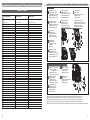
A(DE) Kolbenstangenschutzrohre
(GB) Piston rod protective tubes
Tube de protection
de la tige de piston
Vodící tyč pístnice
Rura ochronna tłoczyska
B(DE) Bremsschläuche
(GB) Brake hoses
Tuyaux de frein
Vzduchové hadice
Przewody hamulcowe
C(DE) Kupplungskopf
(GB) Coupling head
Tête d’attelage
Hlava spojky
Główka sprzęgu
Lok • Locomotive • Lokomotiva • Lokomotywa
D(DE) Kuppelhaken
(GB) Coupling
Crochet d’attelage hook
Hák spřáhla
Hak cięgłowy
(DE) Zur Vervollkommnung des Modelles liegen Zurüstteile, die laut Zeichnung angebracht werden können, bei.
(GB) We have enclosed accessories which can be attached as per drawing to bring the model to perfection.
(FR) Pour compléter le modèle, des accessoires sont joints, ils peuvent être installés conformément au dessin.
(CZ) Pro zdokonalení modelu jsou přiloženy jednotlivé díly příslušenství, které lze na model umístit dle výkresu.
( Dla udoskonalenia modelu dołączono wyposażenie dodatkowe, które można zamocować na modelu zgodnie z rysunkiem.
E(DE) Dampfkupplung
(GB) Steam coupling
Couplage vapeur
Spojka páry
Złącze parowe
A
BC
A
E
B
D

94
Tender • Tendr
(DE)
Die Lok-Betriebsnum-
mern der Artikel wechseln unter
Umständen bei Neuproduktion.
Ersatzteile zu den Art.-Nr. tra-
gen die jeweils in der Produktion
bendlichen Betriebsnummern.
Ersatzteile mit älteren Betriebs-
nummern nur solange Vorrat
reicht.
(GB)
The locomotive opera-
ting numbers of the articles can
potentially change in the event
of new production runs. Spa-
re parts for the article number
bear the operating numbers that
are respectively in production.
Spare parts with older operating
numbers are only available while
stocks last.
(FR)
Les numéros d’exploita-
tion de locomotives des articles
changent parfois lors d’une nou-
velle production. Les pièces de
rechange relatives au n° art. por-
tent respectivement les numéros
d’exploitation se trouvant en
production. Pièces de rechange
avec des numéros d’exploitation
plus anciens jusqu’à rupture du
stock.
(CZ)
Provozní číslo lokomotivy
u tohoto artiklu se může změnit
podle okolností nové výroby.
Náhradní díly jsou k dispozici k
tomuto kat. číslu, které je prá-
vě ve výrobě. Náhradní díly Ke
starším typům jsou pouze do té
doby, dokud vystačí skladové
zásoby.
(PL)
Numery części lokomo-
tywy mogą się zmieniać wraz z
nową produkcją modelu. Części
zamienne dla danego numeru
artykułu za każdym razem mają
numery przyjęte z produkcji.
Części zamienne ze starymi nu-
merami części są dostępne tylko
do wyczerpania zapasu.
!
!
!
!
!
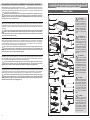
Das Modell ist mit einer Schnittstelle S nach NEM 651 im Tender der Lok ausgestattet. Diese Schnittstelle wird durch An-
heben der Kohleimitation(aufgerastet mit Rastnasen vorn und hinten) zugänglich. Der Entstörsatz kann gegen einen Decoder
getauscht werden. Beim Einsetzen des Decoders ist darauf zu achten, dass er nicht gegen die Schwungscheibe stößt. Als
Decoder empfehlen wir Art.-Nr.: 66032 (Uhlenbrock).
The model is tted with an NEM 651 S interface both in the tender and locomotive. This interface can be accessed by
lifting the imitation coal (it is secured by tabs front and rear). The suppression unit can be exchanged for a decoder. When tting
the decoder it is important to ensure that it does not contact the ywheel. We recommend as a decoder article number: 66032
(Uhlenbrock).
(FR) La maquette est équipée d’une interface S selon la norme NEM 651 dans le tender de la locomotive. Cette interface est
accessible en soulevant l’imitation de charbon (xée avec des ergots d’encliquetage à l’avant et l'arrière). Le kit antiparasitage
peut être remplacé par un décodeur. Lors de la pose du décodeur, veillez à ce qu’il n’entre pas en collision avec le volant d’in-
ertie. Pour le décodeur, nous recommandons l’art. réf. : 66032 (Uhlenbrock).
Model je vybaven rozhraním S dle NEM 651 v tendru lokomotivy. Toto rozhraní je přístupné po nadzvednutí imitace uhlí
(zacvaknuté západkami vpředu a vzadu). Odrušovací sadu je možné vyměnit za dekodér. Při vkládání dekodéru se ujistěte, že
nenarazil na setrvačník. Doporučujeme použití dekodéru Art.-č.: 66032 (Uhlenbrock).
Model wyposażony jest w złącze S zgodne z NEM 651 w tendrze lokomotywy. Złącze jest dostępne po podniesieniu imitacji
węgla (zatrzaśniętej noskami z przodu i z tyłu). Zespół przeciwzakłóceniowy można zastąpić dekoderem. Podczas wstawiania
dekodera należy zwrócić uwagę, aby nie dotykał koła zamachowego. Jako dekoder polecamy art nr.: 66032 (Uhlenbrock).
• •••
!
!
!
!
!
E R S A T Z T E I L L I S T E - T E N D E R
Lfd. Nr. Bezeichnung Art.-Nr.
1
2
3
o.Abb.
o.Abb.
4
5
6
7
8
9
10
11
12
13
14
15
16
17
18
19
20
21
22
23
24
25
26
27
28
29
30
31
32
33
34
35
36
37
38
39
40
o.Abb.
o.Abb.
41
42
43
Oberteil, dek. (02290)
Oberteil, dek. (02291)
Oberteil, dek. (02292)
Kohleaufsatz, lack.
Lampenhalter, oben (02290)
Lampe oben (02291/02292)
Lichteinsatz oben, dek. (02291/02292)
Werkzeugkasten, dek.
Werkzeugkasten, lack. (02292)
Auftritt
Lichteinsatz unten, dek.
Gewicht 1
Entstörleiterplatte
Leiterplatte Tender
Kontaktstift Dm 0,4 x 14,5 mm
Motorklammer
Motor, vollst.
Lichtprisma
Kontaktsatz, mont.
Kuppelkasten
Fahrgestell, lack.
Rohrleitung links
Rohrleitung rechts
Gewicht
Kupplungsdeichsel (lang)
Feder Dm 0,15 x 18,6 mm
Kupplungskopf
Kupplungshaken
Pufferbohle (lang)
Pufferteller, flach
Pufferteller, ballig
Luftbehälter
Gewicht 2
Zahnrad z17/z9
Achse Dm 1,2 x 8,0 mm
Zahnrad z11
Achse Dm 1,5 x 3,7 mm
Zahnrad z11
Achse Dm 1,5 x 7,9 mm
Getriebegehäuse A
Getriebegehäuse B
Drehgestell V, mont. (ohne Haftreifen)
Zahnrad z10
Getriebegehäuse (D), mont.
Treibradsatz mit Haftreifen
Haftreifen
Treibradsatz
Drehgestellblende
Bremsbacken
Drehgestell H, mont. (mit Haftreifen)
206177
206517
207227
206178
301128
301127
206608
206552
206179
301131
206609
351160
396130
396349
390541
301125
201773
301147
201870
301135
206175
301137
301138
351190
301157
380981
300672
330049
301141
316830
316840
301139
351170
301927
341321
341870
340710
323530
341330
301928
301929
201893
323540
201868
201867
227605
201865
301152
301142
201869
S-364381-S.4
04.06.2013
Dampflok
BR 50.35
2
1
5
8
9
10
11
12
16
15
14
27
35
31
32
36
37
33
34
29
30
18
17
4
7
13
19
24
21
28
22
43
23
20
26
25
6
38
39
40
41
42
3
191 Rmin
310
nur bei
02292
Nicht geeignet für Kinder unter 3 Jahren wegen
abnehmbarer und verschluckbarer Kleinteile
und Verletzungsgefahr durch funktionsbedingte
scharfe Ecken und Kanten.
0-3
Dieses Produkt darf am Ende seiner Nutzungsdauer
nicht über den normalen Hausmüll entsorgt werden, sondern
muss an einem Sammelpunkt für das Recycling von elektrischen
und elektronischen Geräten abgegeben werden.
Bitte fragen Sie bei Ihrem Händler oder der Gemeindeverwaltung
nach der zuständigen Entsorgungsstelle.
Technische Änderungen vorbehalten!
Bei Reklamationen
diese Anleitung bitte über Ihren Fachhändler
mitsenden an:
TILLIG Modellbahnen GmbH
Promenade 1, 01855 Sebnitz
Tel. +49 (0)35971 903-0, www.tillig.com
Achtung!
Die Lok-Betriebsnummern der Artikel wechseln unter Umständen bei Neuproduktion.
Ersatzteile zu den Art.-Nr. tragen die jeweils in der Produktion befindlichen Betriebsnummern.
Ersatzteile mit älteren Betriebsnummern nur solange Vorrat reicht.
12
4
8
7
16
9
15
11
10
13
19
21
43
17
5
22
39
3
6
18
30
38
20
41
35
40
29
1
24
26
25
23
28
42
37
14
27
33
34
31
32
36
E R S A T Z T E I L L I S T E - T E N D E R
Lfd. Nr. Bezeichnung Art.-Nr.
1
2
3
o.Abb.
o.Abb.
4
5
6
7
8
9
10
11
12
13
14
15
16
17
18
19
20
21
22
23
24
25
26
27
28
29
30
31
32
33
34
35
36
37
38
39
40
o.Abb.
o.Abb.
41
42
43
Oberteil, dek. (02290)
Oberteil, dek. (02291)
Oberteil, dek. (02292)
Kohleaufsatz, lack.
Lampenhalter, oben (02290)
Lampe oben (02291/02292)
Lichteinsatz oben, dek. (02291/02292)
Werkzeugkasten, dek.
Werkzeugkasten, lack. (02292)
Auftritt
Lichteinsatz unten, dek.
Gewicht 1
Entstörleiterplatte
Leiterplatte Tender
Kontaktstift Dm 0,4 x 14,5 mm
Motorklammer
Motor, vollst.
Lichtprisma
Kontaktsatz, mont.
Kuppelkasten
Fahrgestell, lack.
Rohrleitung links
Rohrleitung rechts
Gewicht
Kupplungsdeichsel (lang)
Feder Dm 0,15 x 18,6 mm
Kupplungskopf
Kupplungshaken
Pufferbohle (lang)
Pufferteller, flach
Pufferteller, ballig
Luftbehälter
Gewicht 2
Zahnrad z17/z9
Achse Dm 1,2 x 8,0 mm
Zahnrad z11
Achse Dm 1,5 x 3,7 mm
Zahnrad z11
Achse Dm 1,5 x 7,9 mm
Getriebegehäuse A
Getriebegehäuse B
Drehgestell V, mont. (ohne Haftreifen)
Zahnrad z10
Getriebegehäuse (D), mont.
Treibradsatz mit Haftreifen
Haftreifen
Treibradsatz
Drehgestellblende
Bremsbacken
Drehgestell H, mont. (mit Haftreifen)
206177
206517
207227
206178
301128
301127
206608
206552
206179
301131
206609
351160
396130
396349
390541
301125
201773
301147
201870
301135
206175
301137
301138
351190
301157
380981
300672
330049
301141
316830
316840
301139
351170
301927
341321
341870
340710
323530
341330
301928
301929
201893
323540
201868
201867
227605
201865
301152
301142
201869
S-364381-S.4
04.06.2013
Dampflok
BR 50.35
2
1
5
8
9
10
11
12
16
15
14
27
35
31
32
36
37
33
34
29
30
18
17
4
7
13
19
24
21
28
22
43
23
20
26
25
6
38
39
40
41
42
3
191 Rmin
310
nur bei
02292
Nicht geeignet für Kinder unter 3 Jahren wegen
abnehmbarer und verschluckbarer Kleinteile
und Verletzungsgefahr durch funktionsbedingte
scharfe Ecken und Kanten.
0-3
Dieses Produkt darf am Ende seiner Nutzungsdauer
nicht über den normalen Hausmüll entsorgt werden, sondern
muss an einem Sammelpunkt für das Recycling von elektrischen
und elektronischen Geräten abgegeben werden.
Bitte fragen Sie bei Ihrem Händler oder der Gemeindeverwaltung
nach der zuständigen Entsorgungsstelle.
Technische Änderungen vorbehalten!
Bei Reklamationen
diese Anleitung bitte über Ihren Fachhändler
mitsenden an:
TILLIG Modellbahnen GmbH
Promenade 1, 01855 Sebnitz
Tel. +49 (0)35971 903-0, www.tillig.com
Achtung!
Die Lok-Betriebsnummern der Artikel wechseln unter Umständen bei Neuproduktion.
Ersatzteile zu den Art.-Nr. tragen die jeweils in der Produktion befindlichen Betriebsnummern.
Ersatzteile mit älteren Betriebsnummern nur solange Vorrat reicht.
gilt für Art.-Nr. 04290
2
1

58
(DE)
Die Lok-Betriebsnum-
mern der Artikel wechseln unter
Umständen bei Neuproduktion.
Ersatzteile zu den Art.-Nr. tra-
gen die jeweils in der Produktion
bendlichen Betriebsnummern.
Ersatzteile mit älteren Betriebs-
nummern nur solange Vorrat
reicht.
(GB)
The locomotive opera-
ting numbers of the articles can
potentially change in the event
of new production runs. Spa-
re parts for the article number
bear the operating numbers that
are respectively in production.
Spare parts with older operating
numbers are only available while
stocks last.
(FR)
Les numéros d’exploita-
tion de locomotives des articles
changent parfois lors d’une nou-
velle production. Les pièces de
rechange relatives au n° art. por-
tent respectivement les numéros
d’exploitation se trouvant en
production. Pièces de rechange
avec des numéros d’exploitation
plus anciens jusqu’à rupture du
stock.
(CZ)
Provozní číslo lokomotivy
u tohoto artiklu se může změnit
podle okolností nové výroby.
Náhradní díly jsou k dispozici k
tomuto kat. číslu, které je prá-
vě ve výrobě. Náhradní díly Ke
starším typům jsou pouze do té
doby, dokud vystačí skladové
zásoby.
(PL)
Numery części lokomo-
tywy mogą się zmieniać wraz z
nową produkcją modelu. Części
zamienne dla danego numeru
artykułu za każdym razem mają
numery przyjęte z produkcji.
Części zamienne ze starymi nu-
merami części są dostępne tylko
do wyczerpania zapasu.
!
!
!
!
!
Lok • Locomotive • Lokomotiva • Lokomotywa
(DE) Das Modell ist ab Werk ausreichend gefettet. Ein Nachfetten ist erst nach ca. 100 Betriebs-
stunden erforderlich. Dabei sind alle beweglichen Teile der Steuerung und die Lokradsätze mit
einem Tropfen säure- und harzfreiem Öl zu versehen. Die Zahnräder des Antriebes sind mit tech-
nischer Vaseline zu fetten. Bei Verwendung von zu viel Fett und Öl besteht infolge Verschmut-
zung die Gefahr von Betriebsstörungen.
The model comes suciently greased at delivery. Regreasing is only necessary after
approx. 100 operating hours. All moving parts of the control unit and the locomotive wheel sets
are oiled with a drop of acid-free and resin-free oil. Use technical Vaseline for the drive gear
wheels. However, if too much grease and oil is used, malfunctions due to contamination may
occur.
Le modèle est susamment graissé à l’usine. Un regraissage n’est nécessaire qu’après
env. 100 heures de service. Huiler toutes les pièces mobiles de la commande et les essieux de
la locomotive avec une goutte d’huile exempte d’acide et de résine. Graisser les roues dentées
de l’entraînement avec une vaseline technique. L’utilisation trop importante de graisse et d’huile
risque de provoquer des défaillances de fonctionnement dues à des saletés.
Model je dostatečně namazán již z výroby. Domazání je potřebné až po cca 100 provoz-
ních hodinách. Mažou se všechny pohyblivé části řízení a soukolí lokomotivy kapkou oleje bez
obsahu kyselin a pryskyřic. Ozubená kola modelu se mažou technickou vazelínou. V případě
použití přílišného množství mazacího tuku oleje vzniká nebezpečí provozních poruch v důsledku
znečištění.
Model został dostatecznie nasmarowany przez producenta. Powtórne smarowanie koniecz-
ne jest dopiero po ok. 100 godzinach eksploatacji. Należy przy tym naoliwić za pomocą kropli
oleju wolnego od żywic i kwasów wszystkie ruchome części sterowania oraz zespoły kół loko-
motywy. Koła zębate napędu należy nasmarować wazeliną techniczną. W przypadku użycia
zbyt dużej ilości smaru lub oleju istnieje niebezpieczeństwo zakłóceń w eksploatacji wskutek
zabrudzenia.
• •••
(DE)
(GB)
(FR)
(CZ)
(PL)
(DE)
(GB)
(FR)
(CZ)
(PL)
E R S A T Z T E I L L I S T E - L O KE R S A T Z T E I L L I S T E - L O K
Lfd. Nr. Bezeichnung Art.-Nr.
1
2
3
4
5
6
7
8
9
10
11
12
13
14
15
16
17
18
19
20
21
22
23
24
25
26
27
28
29
30
31
32
33
Kessel, vollst
Glocke.
Rauchkammertür, vollst.
Führerhaus, vollst.
Kinematik Lok
Feder Kupplung
Umlauf, vollst.
Auftritt
Rahmenoberteil, mont.
Radschleifer Lok, gebogen
Leiterplatte Lok, lack.
Leiterplatte Verbindung
Rahmenvorderteil, mont.
Pufferteller, flach
Pufferteller, ballig
Zylinderpaar mit Schieberdeckel
Gleitbahnträger
Steuerung am Spritzling
(o. Kreuzkopf)
Kreuzkopf links
Kreuzkopf rechts
Lokrahmen, lack.
Kuppelradsatz 1 Dm 11,5 mm
Kuppelradsatz 2 Dm 11,5 mm
Treibradsatz Dm 11,5 mm
Vorläufer, vollst.
Feder Kupplung
Achsfeder Lok, hinten
Achsfeder Lok, vorn
Rahmenunterteil
Senkschraube PT 18x8
Bremsbacken Lok
Kupplungskopf
Kupplungshaken
202038
340630
203773
203772
323580
398200
203778
301239
202025
333320
207758
396481
203776
316830
316840
229841
301005
229851
323290
323280
208380
202804
202806
202809
398200
393110
203781
393140
323120
393210
323600
300672
330049
364385-S.3
03.04.2014
Dampflok
BR 50.0
191 Rmin
310
1
3
7
9
11
13
21
25
29
30
28
26
16
14
17
15
2
5
12
18
22
24
27
30
31
18
19
20
10
6
4
32
33
8
Achtung!
Die Lok-Betriebsnummern der Artikel wechseln
unter Umständen bei Neuproduktion. Ersatzteile
zu den Art.-Nr. tragen die jeweils in der Produktion
befindlichen Betriebsnummern. Ersatzteile mit
älteren Betriebsnummern nur solange Vorrat reicht.
23
23
22
10
17
18
28
3
12
7
15
20
23
22
27
25
1
11
16
29
24
2
8
9
E R S A T Z T E I L L I S T E - L O KE R S A T Z T E I L L I S T E - L O K
Lfd. Nr. Bezeichnung Art.-Nr.
1
2
3
4
5
6
7
8
9
10
11
12
13
14
15
16
17
18
19
20
21
22
23
24
25
26
27
28
29
30
31
32
33
Kessel, vollst
Glocke.
Rauchkammertür, vollst.
Führerhaus, vollst.
Kinematik Lok
Feder Kupplung
Umlauf, vollst.
Auftritt
Rahmenoberteil, mont.
Radschleifer Lok, gebogen
Leiterplatte Lok, lack.
Leiterplatte Verbindung
Rahmenvorderteil, mont.
Pufferteller, flach
Pufferteller, ballig
Zylinderpaar mit Schieberdeckel
Gleitbahnträger
Steuerung am Spritzling
(o. Kreuzkopf)
Kreuzkopf links
Kreuzkopf rechts
Lokrahmen, lack.
Kuppelradsatz 1 Dm 11,5 mm
Kuppelradsatz 2 Dm 11,5 mm
Treibradsatz Dm 11,5 mm
Vorläufer, vollst.
Feder Kupplung
Achsfeder Lok, hinten
Achsfeder Lok, vorn
Rahmenunterteil
Senkschraube PT 18x8
Bremsbacken Lok
Kupplungskopf
Kupplungshaken
202038
340630
203773
203772
323580
398200
203778
301239
202025
333320
207758
396481
203776
316830
316840
229841
301005
229851
323290
323280
208380
202804
202806
202809
398200
393110
203781
393140
323120
393210
323600
300672
330049
364385-S.3
03.04.2014
Dampflok
BR 50.0
191 Rmin
310
1
3
7
9
11
13
21
25
29
30
28
26
16
14
17
15
2
5
12
18
22
24
27
30
31
18
19
20
10
6
4
32
33
8
Achtung!
Die Lok-Betriebsnummern der Artikel wechseln
unter Umständen bei Neuproduktion. Ersatzteile
zu den Art.-Nr. tragen die jeweils in der Produktion
befindlichen Betriebsnummern. Ersatzteile mit
älteren Betriebsnummern nur solange Vorrat reicht.
23
23
22
6
5
19
26
30
E R S A T Z T E I L L I S T E - L O KE R S A T Z T E I L L I S T E - L O K
Lfd. Nr. Bezeichnung Art.-Nr.
1
2
3
4
5
6
7
8
9
10
11
12
13
14
15
16
17
18
19
20
21
22
23
24
25
26
27
28
29
30
31
32
33
Kessel, vollst
Glocke.
Rauchkammertür, vollst.
Führerhaus, vollst.
Kinematik Lok
Feder Kupplung
Umlauf, vollst.
Auftritt
Rahmenoberteil, mont.
Radschleifer Lok, gebogen
Leiterplatte Lok, lack.
Leiterplatte Verbindung
Rahmenvorderteil, mont.
Pufferteller, flach
Pufferteller, ballig
Zylinderpaar mit Schieberdeckel
Gleitbahnträger
Steuerung am Spritzling
(o. Kreuzkopf)
Kreuzkopf links
Kreuzkopf rechts
Lokrahmen, lack.
Kuppelradsatz 1 Dm 11,5 mm
Kuppelradsatz 2 Dm 11,5 mm
Treibradsatz Dm 11,5 mm
Vorläufer, vollst.
Feder Kupplung
Achsfeder Lok, hinten
Achsfeder Lok, vorn
Rahmenunterteil
Senkschraube PT 18x8
Bremsbacken Lok
Kupplungskopf
Kupplungshaken
202038
340630
203773
203772
323580
398200
203778
301239
202025
333320
207758
396481
203776
316830
316840
229841
301005
229851
323290
323280
208380
202804
202806
202809
398200
393110
203781
393140
323120
393210
323600
300672
330049
364385-S.3
03.04.2014
Dampflok
BR 50.0
191 Rmin
310
1
3
7
9
11
13
21
25
29
30
28
26
16
14
17
15
2
5
12
18
22
24
27
30
31
18
19
20
10
6
4
32
33
8
Achtung!
Die Lok-Betriebsnummern der Artikel wechseln
unter Umständen bei Neuproduktion. Ersatzteile
zu den Art.-Nr. tragen die jeweils in der Produktion
befindlichen Betriebsnummern. Ersatzteile mit
älteren Betriebsnummern nur solange Vorrat reicht.
23
23
22
17
E R S A T Z T E I L L I S T E - L O KE R S A T Z T E I L L I S T E - L O K
Lfd. Nr. Bezeichnung Art.-Nr.
1
2
3
4
5
6
7
8
9
10
11
12
13
14
15
16
17
18
19
20
21
22
23
24
25
26
27
28
29
30
31
32
33
Kessel, vollst
Glocke.
Rauchkammertür, vollst.
Führerhaus, vollst.
Kinematik Lok
Feder Kupplung
Umlauf, vollst.
Auftritt
Rahmenoberteil, mont.
Radschleifer Lok, gebogen
Leiterplatte Lok, lack.
Leiterplatte Verbindung
Rahmenvorderteil, mont.
Pufferteller, flach
Pufferteller, ballig
Zylinderpaar mit Schieberdeckel
Gleitbahnträger
Steuerung am Spritzling
(o. Kreuzkopf)
Kreuzkopf links
Kreuzkopf rechts
Lokrahmen, lack.
Kuppelradsatz 1 Dm 11,5 mm
Kuppelradsatz 2 Dm 11,5 mm
Treibradsatz Dm 11,5 mm
Vorläufer, vollst.
Feder Kupplung
Achsfeder Lok, hinten
Achsfeder Lok, vorn
Rahmenunterteil
Senkschraube PT 18x8
Bremsbacken Lok
Kupplungskopf
Kupplungshaken
202038
340630
203773
203772
323580
398200
203778
301239
202025
333320
207758
396481
203776
316830
316840
229841
301005
229851
323290
323280
208380
202804
202806
202809
398200
393110
203781
393140
323120
393210
323600
300672
330049
364385-S.3
03.04.2014
Dampflok
BR 50.0
191 Rmin
310
1
3
7
9
11
13
21
25
29
30
28
26
16
14
17
15
2
5
12
18
22
24
27
30
31
18
19
20
10
6
4
32
33
8
Achtung!
Die Lok-Betriebsnummern der Artikel wechseln
unter Umständen bei Neuproduktion. Ersatzteile
zu den Art.-Nr. tragen die jeweils in der Produktion
befindlichen Betriebsnummern. Ersatzteile mit
älteren Betriebsnummern nur solange Vorrat reicht.
23
23
22
14
13
21
27
E R S A T Z T E I L L I S T E - L O KE R S A T Z T E I L L I S T E - L O K
Lfd. Nr. Bezeichnung Art.-Nr.
1
2
3
4
5
6
7
8
9
10
11
12
13
14
15
16
17
18
19
20
21
22
23
24
25
26
27
28
29
30
31
32
Kessel, vollst. (02290)
Kessel, vollst. (02291/02292)
Glocke
Rauchkammertür, vollst. (02290)
Rauchkammertür, vollst. (02291)
Rauchkammertür, vollst. (02292)
Führerhaus, vollst. (02290)
Führerhaus, vollst. (02291)
Führerhaus, vollst. (02292)
Kinematik Lok
Feder Kupplung
Umlauf, vollst. (02290)
Umlauf, vollst. (02291)
Umlauf, vollst. (02292)
Rahmenoberteil, mont.
Radschleifer Lok, gebogen
Leiterplatte Lok, lack.
Leiterplatte Lok, lack. (02292)
Leiterplatte Verbindung
Rahmenvorderteil, mont. (02290/02291)
Rahmenvorderteil, mont. (02292)
Pufferteller, flach
Pufferteller, ballig
Zylinderpaar mit Schieberdeckel
Gleitbahnträger
Schlammabschneider
Steuerung am Spritzling (
o. Kreuzkopf
)
Kreuzkopf links
Kreuzkopf rechts
Lokrahmen, lack.
Kuppelradsatz Dm 11,5 mm
Treibradsatz Dm 11,5 mm
Vorläufer, vollst. (02290/02292)
Vorläufer, vollst. (02291)
Feder Kupplung
Achsfeder Lok, hinten
Achsfeder Lok, vorn
Rahmenunterteil
Senkschraube PT 18x8
Bremsbacken Lok
Kupplungskopf
Kupplungshaken
201852
202178
340630
201850
202176
202933
201849
202175
202932
323580
398200
201858
202179
202937
201853
333320
206549
207537
396481
201854
202936
316830
316840
229841
301005
301013
229851
323290
323280
208380
201625
201626
201631
201632
398200
393110
393140
323120
393210
323600
300672
330049
Dampflok
BR 50.35
1
3
7
8
10
12
21
24
28
29
27
25
15
17
13
16
14
2
5
11
18
22
23
26
29
30
18
19
20
9
6
4
31
32
191 Rmin
310
nur bei
02292
364381-S.3
04.06.2013
4
21

76
2
7
8
20
22
23
25
26
27
28
29
30
Windleitblech li., lack.
Windleitblech re., lack.
Kessel, vollst.
Rauchkammertür, voll.
Führerhaus, vollst.
Kinematik Lok
Feder Kupplung
Umlauf, vollst.
Rahmenoberteil, mont.
Radschleifer Lok, gebogen
Leiterplatte Lok, vollst.
Leiterplatte Verbindung
Rahmenvorderteil, mont.
Puerteller, ach
Puerteller, ballig
Zylinderpaar mit Schieberdeckel
Gleitbahnträger
Steuerung am Spritzling
(ohne Kreuzkopf)
Kreuzkopf, links
Kreuzkopf, rechts
Lokrahmen, lack.
Kuppelradsatz Dm 11,5 mm
Treibradsatz Dm 11,5 mm
Vorläufer, vollst.
Achsfeder Lok, hinten
Achsfeder Lok, vorn
Rahmenunterteil
Senkschraube PT 1,8x8
Bremsbacken
Kupplungskopf
Kupplungshaken
Smoke deector left, varnish.
Smoke deector right, varnish.
Boiler, complete
Smoke box door, complete
Driver´s cab, complete
Kinematics locomotive
Spring coupling
Running board, complete
Top frame, mounted
Wheel contact locomotive, curved
Circuit board loc., complete
Circuit board connection
Frontside framework, moun.
Buer plate, at
Buer plate, spherical
Cylinder pair with slide box cover
Guide rails
Control on moulding
(without Crosshead)
Crosshead, left
Crosshead, right
Locomotive frame, varnish.
Coupled wheel set Dm 11,5 mm
Driving wheel set Dm 11,5 mm
Extra train, complete
Axle spring locomotive, rear
Axle spring locomotive, front
Bottom frame
Countersunk screw PT 1,8x8
Brake shoe
Coupling head
Clutch hook
Plaque de guidage de vent gauche, laqué
Plaque de guidage de vent droite, laqué
Chaudière, complète
Porte de boîte de fumée, complète
Cabine du conducteur, complète
Cinématique locomotive
Ressort attelage
Circonférence, complète
Partie supérieure de châssis, montée
Capteur de roue locomotive, courbé
Carte de circ. imprimés loc., complète
Carte de circuits imprimés lien
Partie avant du châssis, mon.
Plateau de tampons, plat
Plateau de tampons, en forme de balle
Paire de cylindres avec couvercle
du boîtier de raclage
Support de glissière
Commande sur la pièce
injectée (sans Crosse)
Crosse, gauche
Crosse, droite
Châssis locomotive, laqué
Essieu couplé Dm 11,5 mm
Essieu moteur Dm 11,5 mm
Bogie avant, complète
Ressort d’essieu locomotive, arrière
Ressort d’essieu locomotive, avant
Partie inférieure
Vis à tête conique 1,8x8
Segment de frein
Tête d’attelage
Crochet d’attelage
Lok • Locomotive • Lokomotiva • Lokomotywa
Deektor kouře levý, lak.
Deektor kouře pravý, lak.
Kotel, kompletní
Dýmniční dveře, kompletní
Kabina strojvedoucího, kompletní
Kinematika lokomotiva
Pružina spřáhlo
Rám, kompletní
Horní díl rámu, namontovat
Kontakty kol lokomotiva, zahnuté
Deska s plošnými spoji lok., kompl.
Deska s plošnými spoji připojení
Rám čelníku, namontovat
Kotouč nárazníku, plochý
Kotouč nárazníku, vypouklý
Parní válce, pár se víko skříně
šoupátka
Držák pravítek
Řízení na vstřikovaném
dílu (bez Křižák)
Křižák, levý
Křižák, pravý
Rám lokomotivy, lak.
Kola Dm 11,5 mm
Hnací dvojkolí Dm 11,5 mm
Běhoun přední, kompletní
Odpružení nápravy loko., vzadu
Odpružení nápravy loko., vpředu
Spodní díl rámu
Zápustný šroub 1,8x8
Brzdové čelisti
Hlava spojky
Spojkový hák
Owiewka lewo, lak.
Owiewka prawo, lak.
Kocioł, kompletny
Drzwi dymnicy, kompletny
Budka maszynisty, kompletny
Kinematyka lokomotywa
Sprężyna sprzęg
Przewody cyrkul. kotła, kompl. DR
Część górna ostoi, zmontowana
Ślizgacz kołowy lokomotywa, zgięty
Płytka drukowana lok., kompletny
Płytka drukowana połączenie
Część przednia ostoi, zmontowana
Talerz zderzaka, płaski
Talerz zderzaka, baryłkowaty
Para cylindrów z pokrywa skrzyni
suwakowej
Prowadnica ślizgowa
Sterowanie na wyprasce
(bez Wodzik)
Wodzik, prawo
Wodzik, lewo
Rama lokomotywy, lak.
Zestaw koło. dowiązany Dm 11,5 mm
Zestaw koło. napędowy Dm 11,5 mm
Przedni wózek toczny, kompletny
Sprężyna osiowa lokomotywa, z tyłu
Sprężyna osiowa loko., z przodu
Część dolna ostoi
Śruba z łbem PT 1,8x8
Szczęki hamulcowe
Główka sprzęgu
Hak sprzęgu
Lok • Locomotive • Lokomotiva • Lokomotywa
03030
209078
209077
220298
220299
323580
398200
220296
333320
220295
220305
323290
323280
208380
202806
202809
323600
300672
209078
209077
220375
323580
398200
333320
220373
220305
323290
323280
208380
202806
202809
323600
300672
03032
209078
209077
220708
220709
323580
398200
220705
333320
220707
220305
323290
323280
208380
202806
202809
323600
300672
03033
209078
209077
323580
398200
333320
220305
323290
323280
208380
202806
202809
323600
300672
-
 1
1
-
 2
2
-
 3
3
-
 4
4
-
 5
5
-
 6
6


TILLIG BAHN 03030 Bedienungsanleitung
- Typ
- Bedienungsanleitung
in anderen Sprachen
- français: TILLIG BAHN 03030 Le manuel du propriétaire
- slovenčina: TILLIG BAHN 03030 Návod na obsluhu
- polski: TILLIG BAHN 03030 Instrukcja obsługi
Verwandte Papiere
-
TILLIG BAHN 02236 Bedienungsanleitung
-
-
-
-
-
-
-
-
-