
ISTRUZIONI PER L'INSTALLAZIONE E LA MANUTENZIONE (IT)
INSTRUCTIONS FOR INSTALLATION AND MAINTENANCE (EN)
INSTRUCTIONS POUR L´INSTALLATION ET LA MAINTENANCE (FR)
INSTALLATIONS-UND WARTUNGSANLEITUNGEN (DE)
INSTRUCCIONES DE INSTALACIÓN Y MANTENIMIENTO (ES)
CP2-G CM2-G
DCP2-G DCM2-G
More languagers
are avaiable on the website

ITALIANO
pag.
01
ENGLISH
page
09
FRANÇAIS
page
17
DEUTSCH
seite
25
ESPAÑOL
pág.
33

ITALIANO
1
INDICE
1. GENERALITÀ ..........................................................................................................................................................................................3
1.1 Applicazioni ............................................................................................................................................................................................3
2. Liquidi Pompabili ...................................................................................................................................................................................3
3. Caratteristiche tecniche.........................................................................................................................................................................3
4. GESTIONE ...............................................................................................................................................................................................4
4.1 Immagazzinaggio ...................................................................................................................................................................................4
4.2 Movimentazione .....................................................................................................................................................................................4
4.3 Pesi .........................................................................................................................................................................................................4
4.4 Controllo rotazione albero motore ..........................................................................................................................................................4
4.5 Nuovi impianti .........................................................................................................................................................................................4
5. PROTEZIONI ...........................................................................................................................................................................................4
5.1 Parti in movimento ..................................................................................................................................................................................4
5.2 Livello di rumorosità ................................................................................................................................................................................4
5.3 Parti calde o fredde ................................................................................................................................................................................5
6. INSTALLAZIONE ....................................................................................................................................................................................5
6.1 Fondazione .............................................................................................................................................................................................5
6.2 Collegamento delle tubazioni .................................................................................................................................................................5
6.3 Isolamento ..............................................................................................................................................................................................5
7. ALLACCIAMENTO ELETTRICO .............................................................................................................................................................6
8. MESSA IN FUNZIONE.............................................................................................................................................................................6
8.1 Avviamento .............................................................................................................................................................................................6
8.2 Rodaggio tenuta meccanica ...................................................................................................................................................................6
8.2 Arresto ....................................................................................................................................................................................................6
9. PRECAUZIONI.........................................................................................................................................................................................7
9.1 Pericolo di gelo .......................................................................................................................................................................................7
10. MANUTENZIONE E PULIZIA ..................................................................................................................................................................7
10.1 Regolazione dell'albero ........................................................................................................................................................................7
10.2 Flange cieche .......................................................................................................................................................................................8
10.3 Lubrificazione dei cuscinetti ..................................................................................................................................................................8
11. RICERCA E SOLUZIONE INCONVENIENTI ..........................................................................................................................................8

ITALIANO
2
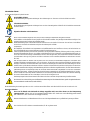
LEGENDA
Nella trattazione sono stati usati i seguenti simboli:
SITUAZIONE DI PERICOLO GENERALE.
Il mancato rispetto delle istruzioni che seguono può causare danni a persone e cose.
SITUAZIONE DI RISCHIO DI SCOSSA ELETTRICA.
Il mancato rispetto delle istruzioni che seguono può
causare una situazione di grave pericolo per la sicurezza delle persone.
Note e informazioni generali.
AVVERTENZE
Una mancata osservanza delle avvertenze può creare situazioni di pericolo per le persone o le cose e far decadere la garanzia del prodotto.
Avvertenze particolari
Prima di intervenire sulla parte elettrica o meccanica dell’impianto togliere sempre la tensione di rete. Sono
ammissibili solo allacciamenti di rete saldamente cablati. L’apparecchio deve essere messo a terra (IEC 536 classe 1, NEC
ed altri standard al riguardo).
Morsetti di rete e i morsetti motore possono portare tensione pericolosa anche a motore fermo.
L’apparecchio deve essere utilizzato solamente per le funzioni per le quali è stato costruito.
Prima di procedere all’installazione leggere attentamente questa documentazione.
L’installazione ed il funzionamento dovranno essere conformi alla regolamentazione di sicurezza del paese di installazione
del prodotto. Tutta l’operazione dovrà essere eseguita a regola d’arte.
Il mancato rispetto delle norme di sicurezza, oltre a creare pericolo per l’incolumità delle persone e danneggiare le
apparecchiature, farà decadere ogni diritto di intervento in garanzia.
Personale Specializzato
È consigliabile che l’installazione venga eseguita da personale competente e qualificato, in possesso dei requisiti tecnici
richiesti dalle normative specifiche in materia.
Per personale qualificato si intendono quelle persone che per la loro formazione, esperienza ed istruzione, nonché le
conoscenze delle relative norme, prescrizioni provvedimenti per la prevenzione degli incidenti e sulle condizioni di servizio,
sono stati autorizzati dal responsabile della sicurezza dell’impianto ad eseguire qualsiasi necessaria attività ed in questa
essere in grado di conoscere ed evitare qualsiasi pericolo (Definizione per il personale tecnico IEC 364).
L’apparecchio può essere utilizzato da bambini di età non inferiore a 8 anni e da persone con ridotte capacità fisiche,
sensoriali o mentali, o prive di esperienza o della necessaria conoscenza, purché sotto sorveglianza oppure dopo che le
stesse abbiano ricevuto istruzioni relative all’uso sicuro dell’apparecchio e alla comprensione dei pericoli ad esso inerenti.
I bambini non devono giocare con l’apparecchio. La pulizia e la manutenzione destinata ad essere effettuata
dall’utilizzatore non deve essere effettuata da bambini senza sorveglianza.
Protezione da sovraccarico. La pompa monofase è dotata di un salvamotore termico. In caso di eventuale
surriscaldamento del motore, il salvamotore spegne la pompa automaticamente. Il tempo di raffreddamento è di circa 15-
20 min. dopo di che la pompa si riaccende automaticamente. Dopo l’intervento del salvamotore è assolutamente
necessario ricercarne la causa ed eliminarla. Consultate Ricerca Guasti.
Le pompe trifase sono sprovviste di salvamotore termico e vanno installate con un quadro di protezione.
L’utilizzo è consentito solamente se l’impianto elettrico è contraddistinto da misure di sicurezza secondo le Normative
vigenti nel paese di installazione del prodotto (per l’Italia CEI64/2).

ITALIANO
3
RESPONSABILITÀ
Il costruttore non risponde del buon funzionamento delle elettropompe o di eventuali danni da queste provocati, qualora le stesse
vengano manomesse, modificate e/o fatte funzionare fuori dal campo di lavoro consigliato o in contrasto con altre disposizioni
contenute in questo manuale.
Declina inoltre ogni responsabilità per le possibili inesattezze contenute nel presente manuale istruzioni, se dovute ad errori di stampa o di
trascrizione. Si riserva il diritto di apportare ai prodotti quelle modifiche che riterrà necessarie od utili, senza pregiudicarne le caratteristiche essenziali.
1. GENERALITÀ
Le pompe della serie IN LINE costituiscono una gamma completa di circolatori. Le presenti istruzioni di installazione e funzionamento
descrivono tutta la gamma di modelli per la serie IN LINE. Il tipo di modello specifico è indicato sulla confezione e sulla targhetta di
identificazione del prodotto.
1.1 Applicazioni
Indicate per realizzare gruppi di pressurizzazione per impianti idrici di piccole, medie e grosse utenze. Possono essere impiegate nei più
svariati campi, quali:
- Impianti di riscaldamento e condizionamento
- Impianti solari
- Alimentazione di caldaie
- Impianti di circolazione
2. LIQUIDI POMPABILI
La macchina è progettata e costruita per pompare acqua con glicole in percentuale fino al 50%, privi di sostanze esplosive e particelle solide
o fibre, con densità pari a 1000 Kg/m3, viscosità cinematica uguale ad 1mm2/s e liquidi non chimicamente aggressivi. L’utilizzo con altri
fluidi è consentito solo previa autorizzazione del costruttore.
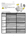
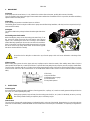
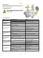
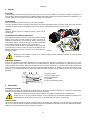
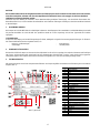
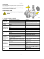
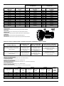
3. CARATTERISTICHE TECNICHE
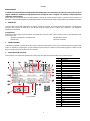
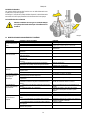
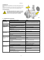
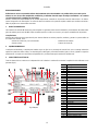
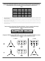
Tutti i dati tecnici sono segnati nell’etichetta tecnica sulla pompa. Di seguito la spiegazione delle varie voci presenti (Fig.1):
Fig.1 Targhetta
Pos.
Descrizione
1
Descrizione
2
Revisione
3
Anno
4
Settimana
5
Numero seriale
6
Massima temperatura del liquido
7
Uso
8
Portata nominale
9
Prevalenza massima
10
Prevalenza minima
11
Classe di isolamento
12
Grado di protezione
13
Prevalenza nominale
14
Tensione nominale
15
Ampere
16
P1
17
P2 HP
18
P2 kW
19
Frequenza
20
Norma MEI
21
Diametro nominale di mandata
22
Diametro girante
23
Valore MEI
24
N°di giri nominali
25
Loghi
26
Codice pompa
27
Efficienza idraulica MEI

ITALIANO
4
4. GESTIONE
4.1 Immagazzinaggio
Tutte le pompe devono essere immagazzinate in luogo coperto, asciutto e con umidità dell’aria possibilmente costante, privo di vibrazioni e
polveri. Vengono fornite nel loro imballo originale nel quale devono rimanere fino al momento dell’installazione. Se così non fosse provvedere
a chiudere accuratamente la bocca di aspirazione e mandata.
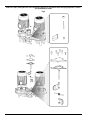
4.2 Movimentazione
Evitare di sottoporre i prodotti ad inutili urti o collisioni.
Le figure seguenti indicano come devono essere sollevate rispettivamente le elettropompe in esecuzione e quelle in esecuzione gemellare
durante la fase di installazione, dopo essere state tolte dall’imballo.(Vedi Fig.7 a fine libretto)
4.3 Pesi
La targhetta adesiva posta sull’imballo riporta l’indicazione del peso totale
dell’elettropompa.
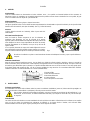
4.4 Controllo
rotazione albero motore
Prima di installare la pompa assicurarsi che le parti in movimento ruotino
liberamente. A tale scopo procedere come segue: togliere il copriventola
dalla sede del coperchio posteriore del motore, svitando i dadi ciechi
a
seconda della modalità di montaggio
. Agendo manualmente sulla ventola
far compiere qualche giro all’albero rotore.
Se ciò non fosse possibile procedere allo smontaggio del corpo pomp
a
allentando
i dadi per verificare la presenza di eventuali corpi estranei al
suo interno. Procedere in senso inverso a quanto descritto per eseguire il
montaggio.
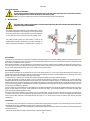
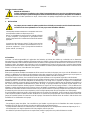
4.5 Nuovi impianti
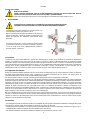
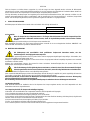
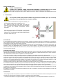
Prima di far funzionare impianti nuovi si devono pulire accuratamente valvole, tubazioni, serbatoi ed attacchi. Spesso scorie di saldatura
scaglie di ossido od altre impurità si staccano solamente dopo un certo periodo di tempo. Per evitare che entrino nella pompa devono essere
raccolte da opportuni filtri. La superficie libera del filtro deve avere una sezione almeno 3 volte maggiore di quella della tubazione su cui il
filtro è montato, in modo da non creare perdite di carico eccessive. Si consiglia l’impiego di filtri TRONCO CONICI costruiti in materiali
resistenti alla corrosione (VEDI DIN 4181):
1-Corpo del filtro
2-Filtro a maglie strette
3-Manometro differenziale
4-Lamiera forata
5-Bocca aspirante della pompa
5. PROTEZIONI
5.1 Parti in movimento
In conformità alle norme antinfortunistiche tutte le parti in movimento (ventole, ecc.) devono essere accuratamente protette, con appositi
strumenti (copriventole, coprigiunti), prima di far funzionare la pompa.
5.2 Livello di rumorosità
I livelli di rumorosità delle pompe con motore fornito di serie sono indicati in tabella A a fine libretto. Si fa presente che nei casi in cui il livelli
di rumorosità LpA superi gli 85dB(A) nei luoghi di installazione si dovranno utilizzare opportune PROTEZIONI ACUSTICHE come previsto
dalle normative vigenti in materia.
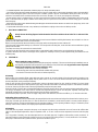
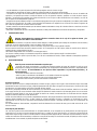
Non forzare sulla ventola con pinze o altri attrezzi per cercare di
sbloccare la pompa in quanto si causerebbe la
deformazione o la rottura della stessa.
Durante il funzionamento della pompa evitare di avvicinarsi alle parti in movimento (albero, ventola, ecc.). ed in ogni caso,
se fosse necessario, solo con un abbigliamento adeguato e a norme di legge in modo da scongiurare l’impigliamento.
Fig.2

ITALIANO
5
5.3 Parti calde o fredde
Nel caso in cui le parti calde o fredde provochino pericolo, si dovrà proteggerle accuratamente per evitare contatti con esse.
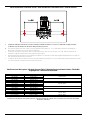
6. INSTALLAZIONE
L’elettropompa deve essere installata in un luogo ben aerato e con
una temperatura ambiente non superiore a 50°C.
Nel caso di installazione del gruppo in ambienti ove sia presente il
pericolo di esplosione si dovranno rispettare le prescrizioni locali
relative alla protezione “Ex” utilizzando esclusivamente motori
appropriati.
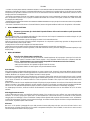
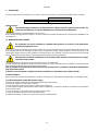
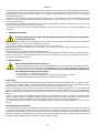
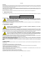
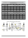
La pompa per potenze fino a 7.5 kW compresi può essere installata
sia in posizione verticale che orizzontale. Per potenze superiori ai
7.5 kW la pompa deve essere obbligatoriamente installata in
posizione verticale. (Vedi Fig.3)
6.1 Fondazione
L’acquirente ha la piena responsabilità per la preparazione della fondazione che deve essere realizzata in conformità alle dimensioni di
ingombro. Se metalliche devono essere verniciate per evitare la corrosione, in piano e sufficientemente rigide per sopportare eventuali
sollecitazioni. Devono essere dimensionate in modo da evitare l’insorgere di vibrazioni dovute a risonanza. Con fondazioni in calcestruzzo
occorre far attenzione che lo stesso abbia fatto buona presa e che sia completamente asciutto prima di sistemarvi il gruppo. La superficie di
appoggio dovrà risultare perfettamente piana ed orizzontale. Posizionata la pompa sulla fondazione si dovrà controllare che sia
perfettamente in bolla con l’ausilio di una livella. Nel caso contrario dovranno essere utilizzati opportuni spessori.
6.2 Collegamento delle tubazioni
Evitare che le tubazioni metalliche trasmettano sforzi eccessivi alle bocche della pompa, per non creare deformazioni o rotture. Le dilatazioni
per effetto termico delle tubazioni devono venire compensate con opportuni provvedimenti per non gravare sulla pompa stessa. Le
controflange delle tubazioni devono essere parallele alle flange della pompa.
Per ridurre al minimo il rumore si consiglia di montare giunti antivibranti sulle tubazioni di aspirazione e di mandata.
È sempre buona norma posizionare la pompa il più vicino possibile al liquido da pompare. È consigliabile l’impiego di un tubo di aspirazione
di diametro maggiore di quello della bocca aspirante dell’elettropompa. Se il battente all’aspirazione è negativo è indispensabile installare in
aspirazione una valvola di fondo con adeguate caratteristiche. Passaggi irregolari tra diametri delle tubazioni e curve strette aumentano
notevolmente le perdite di carico. L’eventuale passaggio da una tubazione di piccolo diametro ad una di diametro maggiore deve essere
graduale. Di regola la lunghezza del cono di passaggio deve essere 5÷7 la differenza dei diametri. Controllare accuratamente che le
giunzioni del tubo aspirante non permettano infiltrazioni d’aria. Controllare che le guarnizioni tra flange e controflange siano ben centrate in
modo da non creare resistenze al flusso nella tubazione. Per evitare il formarsi di sacche d’aria nel tubo di aspirazione, prevedere una
leggera pendenza positiva del tubo di aspirazione stesso verso l’elettropompa.
Nel caso di installazione di più pompe, ogni pompa deve avere la propria tubazione aspirante. Fa eccezione la sola pompa di riserva (se
prevista), che entrando in funzione solo nel caso di avaria della pompa principale assicura il funzionamento di una sola pompa per tubazione
aspirante. A monte ed a valle della pompa devono essere montate delle valvole di intercettazione in modo da evitare di dover svuotare
l’impianto in caso di manutenzione alla pompa.
6.3 Isolamento
− Per proteggere la pompa da depositi è opportuno non installarla nel punto più basso dell’impianto. Effettuare il montaggio della pompa
sull’impianto solo alla fine di tutti i lavori di saldatura e verificare che lo stesso sia ben pulito.
− La pompa deve essere installato in un luogo ben aerato, protetto dalle intemperie e con una temperatura ambiente non superiore a 50°C.
− Le elettropompe con grado di protezione IPX5 sono protette contro i getti d'acqua.
− Per facilitare le operazioni di controllo e sostituzione installare la pompa in posizione di facile accesso.
PERICOLO DI USTIONI!!
Il fluido contenuto nell’impianto, oltre che ad alta temperatura e pressione, può trovarsi anche sotto forma di
vapore! Può essere pericoloso anche solo toccare la pompa o parti dell’impianto.
Le pompe possono contenere piccole quantità di acqua residua proveniente dai collaudi.
Consigliamo di lavarle brevemente con acqua pulita prima dell’installazione definitiva.
Fig.3

ITALIANO
6
− Le frecce sul corpo pompa indicano la direzione del flusso. Si raccomanda l’utilizzo di saracinesche di intercettazione sulle tubazioni di
aspirazione e di mandata, per evitare lo svuotamento dell’impianto in caso di riparazione. Prevedere inoltre un circuito di by-pass tra mandata
ed aspirazione per garantire un minimo ricircolo nel caso in cui sulle tubazioni venissero utilizzate delle elettrovalvole, in modo da non far
insorgere pericolose sovratemperature.
− Assicurarsi che l’impianto sia fornito di un sistema di spurgo per l’aria e che il vaso di espansione (se previsto) sia installato prima della
bocca di aspirazione. Quando, invece, la pompa è installata sulla mandata di un circuito a vaso aperto, accertarsi che il tubo di sicurezza
sia collegato prima della pompa.
− Montare la pompa sull’impianto evitando che le tubazioni metalliche trasmettano al corpo pompa sforzi o tensioni eccessive che potrebbero
creare incrinature e rotture.
− Per evitare la trasmissione del rumore o di eventuali vibrazioni, montare dei giunti antivibranti sulle bocche di aspirazione e di mandata.
7. ALLACCIAMENTO ELETTRICO
Nel caso di motori trifase con avviamento stella-triangolo si deve assicurare che il tempo di commutazione tra stella e triangolo sia il più
ridotto possibile e che rientri nella tabella B a fine libretto.
Prima di accedere alla morsettiera e operare sulla pompa accertarsi che sia stata tolta tensione.
Verificare la tensione di rete prima di eseguire qualsiasi collegamento. Se corrisponde a quella di targa procedere al collegamento dei fili
alla morsettiera dando priorità a quello di terra.
Le pompe devono essere sempre collegate ad un interruttore esterno.
I motori devono essere protetti da appositi salvamotori tarati opportunamente in rapporto alla corrente di targa.
Negli impianti dove è prevista l’esecuzione gemellare, ai fini della continuità di servizio, prevedere cablaggi ed interruttori separati per ogni
singola pompa.
8. MESSA IN FUNZIONE
8.1 Avviamento
Prima dell’avviamento è indispensabile riempire l’impianto con acqua e spurgare l’aria. Spurgare il corpo pompa dall'aria residua inserendo
un tubetto nel rubinetto di sfiato e svitando leggermente fino a quando fuoriesce solo acqua. Questo per far in modo che la tenuta meccanica
risulti ben lubrificata e che la pompa cominci subito a funzionare in modo regolare.
Dare tensione e controllare il giusto senso di rotazione che, osservando il motore dal lato ventola, dovrà avvenire in senso orario. Il controllo
dovrà essere eseguito dopo aver alimentato la pompa agendo sull’interruttore generale con una veloce sequenza marcia arresto. Nel caso
in cui il senso di rotazione sia contrario invertire tra di loro due qualsiasi conduttori di fase, dopo aver isolato la pompa dalla rete di
alimentazione.
Quando il circuito idraulico è stato completamente riempito di liquido aprire progressivamente la saracinesca di mandata fino alla massima
apertura consentita. Si deve infatti controllare il consumo energetico del motore e confrontarlo con quello indicato in targhetta specialmente
nel caso in cui si sia intenzionalmente dotata la pompa di motore con potenza ridotta (controllare le caratteristiche di progetto).
Con l’elettropompa in funzione, verificare la tensione di alimentazione ai morsetti del motore che non deve differire del +/- 5% dal valore
nominale.
8.2 Rodaggio tenuta meccanica
Le facce della tenuta meccanica sono lubrificate dal liquido pompato, il che comporta che possa verificarsi una certa perdita dalla tenuta
meccanica. Se si avvia la pompa per la prima volta o se viene installata una nuova tenuta meccanica, è necessario un certo periodo di
rodaggio prima che il trafilaggio si riduca a livelli minimi. Il tempo richiesto dipende dalle condizioni di funzionamento, ovvero, cambiando le
condizioni di funzionamento, si inizierà un nuovo periodo di rodaggio. In condizioni normali, il liquido che fuoriesce evapora immediatamente.
Come risultato, la perdita di liquido risulta invisibile.
8.3 Arresto
Nel caso in cui sia previsto il pompaggio di acqua calda prevedere l’arresto della pompa solo dopo aver escluso la fonte di calore e aver
fatto trascorrere un periodo di tempo tale da far scendere la temperatura del liquido a valori accettabili, in modo da non creare eccessivi
aumenti di temperatura all’interno del corpo pompa.
Rispettare rigorosamente gli schemi elettrici riportati all’interno della scatola morset
tiera e quelli riportati nella
Tab. C a fine libretto.
Prima di avviare l’elettropompa controllare che:
− la pompa sia regolarmente adescata, provvedendo al totale riempimento del corpo pompa. Questo per far in modo che
la pompa cominci a funzionare subito in modo regolare e che il dispositivo di tenuta (meccanica o baderna) risulti ben
lubrificata. Il funzionamento a secco provoca danni irreparabili sia alla tenuta meccanica che a baderna;
− i circuiti ausiliari siano stati correttamente collegati;
− tutte le parti in movimento siano protette da appositi sistemi di sicurezza;
− il collegamento elettrico sia stato eseguito come precedentemente indicato.

ITALIANO
7
Per un lungo periodo di arresto chiudere l’organo di intercettazione della tubazione aspirante, ed eventualmente, se previsti, tutti gli attacchi
ausiliari di controllo. Per garantire la massima funzionalità dell’impianto sarà necessario prevedere dei brevi periodi di messa in marcia (5 –
10 min) ad intervalli di tempo che possono essere di 1 - 3 mesi.
Nel caso in cui la pompa venga rimossa dall’impianto ed immagazzinata procedere come indicato in par.5.1
9. PRECAUZIONI
L’elettropompa non deve essere sottoposta ad un eccessivo numero di avviamenti per ora. Il numero massimo ammissibile è il seguente:
Numero massimo avviamenti/ora
Motori Trifase fino a 4 Kw
20 ÷ 30
Motori Trifase da 5.5 a 44 Kw
5 ÷ 10
9.1 Pericolo di gelo
Non richiudere il tappo di scarico finché la pompa non verrà utilizzata nuovamente.
L’avviamento dopo lunga inattività richiede il ripetersi delle operazioni descritte nei paragrafi “AVVERTENZE” ed “AVVIAMENTO”
precedentemente elencate.
10. MANUTENZIONE E PULIZIA
In ogni caso tutti gli interventi di riparazione e manutenzione si devono effettuare solo dopo aver scollegato la pompa dalla rete di
alimentazione. Assicurarsi che quest’ultima non possa essere accidentalmente inserita.
Durante la manutenzione programmata scaricare la condensa eventualmente presente nel motore agendo sul piolo (per elettropompe con
grado di protezione al motore IP55).
Si dovranno inoltre osservare le disposizioni di legge per lo smaltimento di eventuali liquidi nocivi.
L’elettropompa nel funzionamento normale non richiede alcun tipo di manutenzione. Tuttavia è consigliabile un periodico controllo
dell’assorbimento di corrente, della prevalenza manometrica a bocca chiusa e della massima portata, che permetta di individuare
preventivamente guasti od usure.
Dopo qualsiasi operazione che implichi lo smontaggio della testata motore dal corpo pompa, è consigliabile sostituire l’OR di
tenuta tra corpo pompa e supporto.
Inoltre in caso di manutenzione o sostituzione del circolatore completo si richiede di utilizzare un nuovo set di guarnizioni.
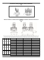
10.1 Regolazione dell'albero
Se il motore è stato rimosso durante l'installazione o per la riparazione della pompa, l'albero della pompa deve essere regolato dopo aver
rimontato il motore.
10.1.1 Regolazione dell'albero per pompe con giunto in due parti
Assicurarsi che il perno dell'albero sia montato nell'albero della pompa. Regolare l’albero della pompa come segue:
1. Rimuovere le griglie coprigiunto con un cacciavite.
2. Fissare la vite ad esagono incassato nel giunto e non serrarla.
3. Sollevare al massimo il giunto e l'albero della pompa (verso il motore) con un cacciavite o uno strumento simile, in modo che la pompa e
gli alberi del motore entrino in contatto.
4. Serrare la vite ad esagono incassato nel giunto a 5 Nm (0,5 kpm).
5. Verificare che gli spazi su entrambi i lati del giunto siano identici.
6. Serrare le viti due alla volta (un lato per volta) alla coppia indicata di seguito.
Verificare che la fuoriuscita del liquido non danneggi cose o persone specialmente negli impianti che utilizzano
acqua calda. Lo scarico dell’impianto deve essere eseguito solo quando la temperatura del liquido ha raggiunto
quella ambiente.
L’elettropompa non può essere smontata se non da personale
specializzato e qualificato in possesso dei requisiti
richiesti dalle normative specifiche in materia.
Nel caso in cui per eseguire la manutenzione sia necessario scaricare il liquido, verificare che la fuoriuscita del
liquido non danneggi cose o persone specialmente negli impianti che utilizzano acqua calda.

ITALIANO
8
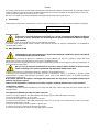
10.2 Flange cieche
Per le pompe gemellari è disponibile una flangia cieca con una guarnizione
per il corpo pompa.
Se è necessaria la riparazione di una delle due pompe, la flangia cieca viene
montata per consentire il funzionamento
dell’altra pompa.
10.
3 Lubrificazione dei cuscinetti
Provvedere alla manutenzione in base al tipo di
cuscinetto presente in targhetta dati tecnici.
Vedi tabelle
a fine libretto.
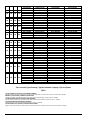
11. RICERCA E SOLUZIONE INCONVENIENTI
Problemi
Verifiche (possibili cause)
Rimedi
Il motore non parte e
non genera rumore.
− Verificare i fusibili di protezione.
Se bruciati sostituirli.
− Verificare le connessioni elettriche.
Un eventuale ed immediato ripristino del guasto
sta ad indicare che il motore è in corto circuito.
− Verificare che il motore sia sotto tensione.
La pompa eroga una
portata insufficiente.
− Girante usurata od ostruita.
Sostituire la girante o rimuovere l’ostruzione.
− Verificare il corretto senso di rotazione per i motori
trifase.
Invertire tra di loro due fili di alimentazione.
Il motore non parte ma
genera rumori.
− Assicurarsi che la tensione di alimentazione
corrisponda a quella di targa.
− Controllare che le connessioni siano state eseguite
correttamente.
Correggere eventuali errori.
− Verificare in morsettiera la presenza di tutte le fasi.
In caso negativo ripristinare la fase mancante.
− L’albero è bloccato. Ricercare possibili ostruzioni della
pompa o del motore.
Rimuovere l’ostruzione.
− Condensatore in cortocircuito o interrotto.
Sostituire il condensatore.
Il motore gira con
difficoltà.
− Verificare la tensione di alimentazione che potrebbe
essere insufficiente.
− Verificare possibili raschiamenti tra parti mobili e parti
fisse.
Provvedere ad eliminare la causa del
raschiamento.
− Verificare lo stato dei cuscinetti.
Sostituire eventualmente i cuscinetti danneggiati.
La protezione (esterna)
del motore interviene
subito dopo
l’avviamento.
− Verificare la presenza in morsettiera di tutte le fasi
(per i modelli trifase)
In caso negativo ripristinare la fase mancante.
− Verificare possibili contatti aperti o sporchi nella
protezione.
Sostituire o ripulire il componente interessato.
− Verificare il possibile isolamento difettoso del motore
controllando la resistenza di fase e l’isolamento verso
massa.
Sostituire la cassa motore con statore o ripristinare
possibili cavi a massa.
La protezione del
motore interviene con
troppa frequenza.
− Verificare che la temperatura ambiente non sia troppo
elevata.
Aerare adeguatamente l’ambiente di installazione
della pompa.
− Verificare la taratura della protezione.
Eseguire la taratura ad un valore di corrente
adeguato all’assorbimento del motore a pieno
carico.
− Controllare la velocità di rotazione del motore.
Consultare i dati di targa del motore.
− Verificare lo stato dei cuscinetti.
Sostituire i cuscinetti danneggiati
La pompa vibra con
funzionamento
rumoroso.
− Verificare che la pompa o/e le tubazioni siano ben
fissate.
Bloccare le parti allentate.
− La pompa cavita.
Aumentare, pur restando nei limiti consentiti, la
pressione del sistema.
− La pompa funziona oltre i dati di targa.
Ridurre la portata.
− Verificare che la tensione di alimentazione
corrisponda a quella di targa.
Fig.4

ENGLISH
9
INDEX
1. GENERAL ..............................................................................................................................................................................................11
1.1 Applications ..........................................................................................................................................................................................11
2. PUMPED FLUIDS ..................................................................................................................................................................................11
3. Technical characteristics ....................................................................................................................................................................11
4. MANAGEMENT .....................................................................................................................................................................................12
4.1 Storage .................................................................................................................................................................................................12
4.2 Handling ...............................................................................................................................................................................................12
4.3 Weights .................................................................................................................................................................................................12
4.4 Checking motor shaft rotation ...............................................................................................................................................................12
4.5 New systems ........................................................................................................................................................................................12
5. PROTECTIONS .....................................................................................................................................................................................12
5.1 Moving parts .........................................................................................................................................................................................12
5.2 Noise level ............................................................................................................................................................................................12
5.3 Hot and cold parts ................................................................................................................................................................................13
6. INSTALLATION .....................................................................................................................................................................................13
6.1 Foundation ............................................................................................................................................................................................13
6.2 Connecting the pipes ............................................................................................................................................................................13
6.3 Insulation ..............................................................................................................................................................................................13
7. ELECTRICAL CONNECTION ...............................................................................................................................................................14
8. STARTING UP .......................................................................................................................................................................................14
8.1 Starting .................................................................................................................................................................................................14
8.2 Breaking in the mechanical seal ...........................................................................................................................................................14
8.2 Stopping ...............................................................................................................................................................................................14
9. PRECAUTIONS .....................................................................................................................................................................................15
9.1 Danger of frost ......................................................................................................................................................................................15
10. MAINTENANCE AND CLEANING ........................................................................................................................................................15
10.1 Shaft adjustment .................................................................................................................................................................................15
10.2 Blanking flanges .................................................................................................................................................................................16
10.3 Lubricating the bearings .....................................................................................................................................................................16
11. TROUBLESHOOTING ...........................................................................................................................................................................16

ENGLISH
10
KEY
The following symbols have been used in the discussion:
SITUATION OF GENERAL DANGER
.
Failure to respect the following instructions may cause damage to persons and property
.
SITUATION OF RISK OF ELECTRIC
SHOCK.
Failure to respect the following instructions may cause a situation of serious danger for personal safety
.
Notes and general information
.
WARNINGS
Failure to observe the warnings may create situations of risk for persons or property and will void the product guarantee.
Particular warnings
Always switch off the mains power supply before working on the electrical or mechanical part of the system. Only
firmly cabled mains connections are admissible. The appliance must be earthed (IEC 536 class 1, NEC and other applicable
standards).
Mains terminals and motor terminals may still have dangerous voltage when the motor is stopped.
The appliance may only be used for the functions for which it was designed.
Under certain calibration conditions, the converter can start automatically after a power failure.
Read this documentation carefully before installation.
Installation and operation must comply with the local safety regulations in force in the country in which the product is
installed. Everything must be done in a workmanlike manner.
Failure to respect the safety regulations not only causes risk to personal safety and damage to the equipment, but
invalidates every right to assistance under guarantee.
Skilled personnel
It is advisable that installation be carried out by competent, skilled personnel in possession of the technical qualifications
required by the specific legislation in force.
The term skilled personnel means persons whose training, experience and instruction, as well as their knowledge of the
respective standards and requirements for accident prevention and working conditions, have been approved by the person
in charge of plant safety, authorizing them to perform all the necessary activities, during which they are able to recognize
and avoid all dangers (Definition for technical personnel IEC 364).
The appliance may be used by children over 8 years old and by persons with reduced physical, sensory or mental
capacities, or who lack experience or knowledge, on condition that they are under supervision or after they have received
instructions concerning the safe use of the appliance and the understanding of the dangers involved. Children must not
play with the appliance. Cleaning and maintenance intended to be carried out by the user must not be performed by
children without supervision.
Overload protection. The single-phase pump is equipped with a thermal motor protector. If the motor overheats, the motor
protector switches the pump off automatically. The cooling time is about 15-20 min. after which the pump automatically
switches on again. After the motor protector has tripped, it is absolutely necessary to find the cause and eliminate it. See
Troubleshooting. Three-phase pumps have no thermal motor protector and must be installed with a protection panel.
Use is allowed only if the electric system is in possession of safety precautions in accordance with the regulations in force
in the country where the product is installed (for Italy CEI64/2).

ENGLISH
11
RESPONSIBILITY
The Manufacturer does not vouch for correct operation of the electro pumps or answer for any damage that they may cause if they
have been tampered with, modified and/or run outside the recommended work range or in contrast with other indications given in
this manual.
The Manufacturer declines all responsibility for possible errors in this instructions manual, if due to misprints or errors in copying. The
Manufacturer reserves the right to make any modifications to the products that it may consider necessary or useful, without affecting their
essential characteristics.
1. GENERAL
The pumps in the IN LINE series represent a complete range of circulators. These installation and operating instructions describe the entire
range of models for the IN LINE series The specific type of model is indicated on the pack and on the product identification plate.
1.1 Applications
Indicated for booster sets for water systems of small, medium and large users. They can be used in the most varied fields, such as:
- Heating and conditioning systems
- Solar energy systems
- Boiler supply
- Circulation systems
2. PUMPED FLUIDS
The machine is designed and built to pump water with up to 50% glycol, free from explosive substances and solid particles or fibers, with a
density of 1000 kg/m³ and a kinematic viscosity of 1 mm²/s, and chemically non-aggressive liquids. Use with other fluids is allowed only with
the manufacturer’s authorization.
3. TECHNICAL CHARACTERISTICS
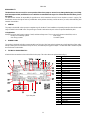
All technical data are marked on the technical label on the pump. The various items are explained below (Fig. 1):
Fig.1 Data plate
Pos.
Description
1
Description
2
Revision
3
Year
4
Week
5
Serial number
6
Maximum liquid temperature
7
Use
8
Rated flow
9
Maximum head
10
Minimum head
11
Insulation class
12
Degree of protection
13
Rated head
14
Rated voltage
15
Ampere
16
P1
17
P2 HP
18
P2 kW
19
Frequency
20
MEI Standard
21
Rated delivery diameter
22
Impeller diameter
23
MEI value
24
Rated number of revolutions
25
Logos
26
Pump code
27
MEI hydraulic efficiency

ENGLISH
12
4. MANAGEMENT
4.1 Storage
All the pumps must be stored indoors, in a dry, vibration-free and dust-free environment, possibly with constant air humidity.
They are supplied in their original packaging and must remain there until the time of installation. If this is not possible, the intake and delivery
aperture must be accurately closed.
4.2 Handling
Avoid subjecting the products to needless impacts or collisions.
The following figures show how single and twin electric pumps must be lifted during installation, after they have been unpacked (see Fig.7
at the end of the booklet).
4.3 Weights
The adhesive label on the package indicates the total weight of the
electro
pump
.
4.4
Checking motor shaft rotation
Before installing the pump, ensure that moving parts rotate freely. To do
this, proceed as follows: remove the fan cover from the seat of t
he rear
engine cover, unscrewing the blank nuts according to the installation
method. Manually operating the fan, turn the rotor shaft a few revolutions.
If this is not possible, proceed to disassemble the pump body by loosening
the nuts to check for any f
oreign bodies inside. Proceed in the opposite
direction to that described for assembly.
4.5 New systems
Before running new systems the valves, pipes, tanks and couplings must be cleaned accurately. Often welding waste, flakes of oxide or
other impurities fall off after only a certain period of time. To prevent them from getting into the pump they must be caught by suitable filters.
The free surface of the filter must have a section at least 3 times larger than the section of the pipe on which the filter is fitted, so as not to
create excessive load losses. We recommend the use of TRUNCATED CONICAL filters made of corrosion-resistant materials (SEE DIN
4181):
1- Filter body
2- Narrow mesh filter
3- Differential pressure gauge
4- Perforated sheet
5- Pump intake aperture
5. PROTECTIONS
5.1 Moving parts
In accordance with accident-prevention regulations, all moving parts (fans, couplings, etc.) must be accurately protected with special devices
(fan covers, ecc.) before operating the pump.
5.2 Noise level
The noise levels of pumps with standard motor are indicated in table A at the end of the booklet. Remember that, in cases where the LpA
noise levels exceed 85 Db(A), suitable HEARING PROTECTION must be used in the place of installation, as required by the regulations in
force.
Do not force the fan with pliers or other tools to try to free the pump as this could cause deformation or breakage of the
pump.
During pump operation, keep well away from the moving parts (shaf
t, fan, etc.) unless it is absolutely necessary, and only
then wearing suitable clothing as required by law, to avoid being caught.
Fig.2

ENGLISH
13
5.3 Hot and cold parts
If the hot or cold parts are a source of danger, they must be accurately protected to avoid contact with them.
6. INSTALLATION
The electro pump must be fitted in a well ventilated place, with an
environment temperature not exceeding 50°C. If the unit is installed
in a location where there is a risk of explosion, the local regulations
on "Ex" protection must be respected, using only suitable motors.
The pump for power ratings up to and including 7.5 kW can be
installed either vertically or horizontally. For powers exceeding 7.5
kW, the pump must be installed in a vertical position. (See Fig.3)
6.1 Foundation
The buyer is fully responsible for preparing the foundation which must be made in conformity with the dimensions. Metal foundations must
be painted to avoid corrosion; they must be level and sufficiently rigid to withstand any stress. Their dimensions must be calculated to avoid
the occurrence of vibrations due to resonance.
With concrete foundations, care must be taken to ensure that the concrete has set firmly and is completely dry before placing the unit on it.
The surface that it sits on must be perfectly flat and horizontal. After the pump has been positioned on the foundation, check with a spirit
level to ensure that it is sitting perfectly level. If not, suitable shims must be inserted.
6.2 Connecting the pipes
Ensure that the metal pipes do not transmit excess force to the pump apertures, so as to avoid causing deformations or breakages. Any
expansion due to the heat of the pipes must be compensated with suitable precautions to avoid weighing down on the pump. The counter
flanges of the pipes must be parallel to the flanges of the pump.
To reduce noise to a minimum it is advisable to fit vibration-damping couplings on the intake and delivery pipes.
It is always good practice to place the pump as close as possible to the liquid to be pumped. It is advisable to use a suction pipe with a
diameter larger than that of the intake aperture of the electro pump. If the head at intake is negative, it is indispensable to fit a foot valve with
suitable characteristics at intake. Irregular passages between the diameters of the pipes and tight curves considerably increase load losses.
Any passage from a pipe with a small diameter to one with a larger diameter must be gradual. Usually the length of the passage cone must
be 5 to 7 times the difference in diameter.
Check accurately to ensure that the joins in the intake pipe do not allow air infiltrations. Ensure that the gaskets between flanges and counter
flanges are well centered so as not to create resistances to the flow in the pipes. To prevent the formation of air pockets, the intake pipe
must slope slightly upwards towards the pump.
If more than one pump is installed, each pump must have its own intake pipe. The only exception is the reserve pump (if envisaged) which,
as it starts up only in the case of breakdown of the main pump, ensures the operation of only one pump for each intake pipe. Interception
valves must be fitted upstream and downstream from the pump so as to avoid having to drain the system when carrying out pump
maintenance.
6.3 Insulation
− To protect the pump from deposits, it should not be installed at the lowest point of the system. Only install the pump on the system after
all welding work has been completed and check that the system is properly cleaned.
− The pump must be installed in a well ventilated place, protected from unfavorable weather conditions, and with an environment temperature
not higher than 50°C.
− The electric pumps with IPX5 degree of protection are protected against water jets.
DANGER OF BURNING!!
As well as being at high temperature and high pressure, the fluid in the system may also be in the form of steam!
It may be dangerous even to touch the pump or parts of the system.
The pumps may contain small quantities of residual water from testing. We advise flushing them briefly with clean
water before their final installation.
Fig.3

ENGLISH
14
− To facilitate inspection and replacement, install the pump in an easily accessible position.
− The arrows on the pump body indicate the direction of flow. The use of gate valves on the suction and delivery pipes is recommended in
order to avoid draining the system in the event of repairs. In addition, provide a by-pass circuit between delivery and suction to ensure a
minimum of recirculation in the event that solenoid valves are used on the pipes, so as not to cause dangerous overheating.
− Ensure that the system is equipped with an air vent system and that the expansion tank (if fitted) is installed before the suction mouth.
When, on the other hand, the pump is installed on the delivery side of an open vessel circuit, make sure that the safety pipe is connected
before the pump.
− Mount the pump on the system without allowing the metal pipes to transmit excessive stresses or strains to the pump body, which could
lead to cracks and breakage.
− To prevent the transmission of noise or any vibrations, fit anti-vibration couplings to the suction and delivery mouths.
7. ELECTRICAL CONNECTION
In the case of three-phase motors with star-delta starting, it must be ensured that the switching time between star and delta is as short as
possible and falls within table B at the end of the booklet.
Before accessing the terminal board and working on the pump, make sure that power has been switched off.
Check the mains voltage before making any connections. If it corresponds to the data plate, connect the wires to the terminal board, giving
priority to the earth wire.
The pumps must always be connected to an external switch.
The motors must be protected by motor protectors that are appropriately rated in relation to the current indicated on the data plate.
In systems where the twin version is envisaged, for the purposes of continuity of service, provide separate wiring and switches for each
individual pump.
8. STARTING UP
8.1 Starting
Before starting, it is essential to fill the system with water and to vent the air. Vent the residual air from the pump body by inserting a hose
into the venting tap and unscrewing it slightly until only water comes out. This is to ensure that the mechanical seal is well lubricated and
that the pump starts running smoothly immediately.
Power up and check the correct direction of rotation which, looking at the motor from the fan side, should be clockwise. The check should
be carried out after the pump has been powered up by acting on the main switch with a fast start-stop sequence. If the direction of rotation
is reversed, invert any two phase leads, after having isolated the pump from the power mains.
When the hydraulic circuit has been completely filled with liquid, gradually open the delivery gate valve to the maximum permissible opening.
The energy consumption of the motor must be checked and compared with the value on the data plate, especially if the pump was
intentionally equipped with a motor with reduced power (check the design specifications).
With the electric pump in operation, check the supply voltage at the motor terminals, which must not differ by +/- 5% from the rated value.
8.2 Breaking in the mechanical seal
The faces of the mechanical seal are lubricated by the pumped liquid, which means that some leakage from the mechanical seal may occur.
If the pump is started up for the first time or if a new mechanical seal is installed, a certain break-in period is necessary before leakage is
reduced to a minimum. The time required depends on the operating conditions, i.e. if the operating conditions change, a new break-in period
will begin. Under normal conditions, the escaping liquid evaporates immediately.
8.3 Stopping
If hot water is to be pumped, arrange that the pump can be stopped only after having excluded the source of heat and let sufficient time
elapse to allow the liquid temperature to drop to acceptable values, so as not to create excessive temperature increases inside the pump
body.
For a long period of inactivity, close the interception device on the intake pipe and, if supplied, all the auxiliary control connections. To
guarantee maximum system functionality it will be necessary to arrange for brief running periods (5 - 10 min) at intervals of 1 to 3 months.
If the pump is removed from the system and stored, proceed as indicated in par 4.1
Strictly observe the wiring diagrams inside the terminal board box and those shown in the Tab. C
at the end of the
booklet.
Before starting the pump, check that:
−
the pump has been properly primed, filling the pump body completely. This ensures that the pump immediately starts to
work regularly and that the seal (mechanical seal or stuffing box seal) is well lubricated.
Dry operation causes irreparable
damage to the mechanical seal and the stuffing box seal;
− the auxiliary circuits have been correctly connected;
− all the moving parts have been protected with suitable safety systems;
− the electrical connection has been made as indicated previously.

ENGLISH
15
9. PRECAUTIONS
The electric pump must not be subjected to an excessive number of starts per hour. The maximum permissible number is as follows:
Maximum number of starts/hour
Three-phase motors up to 4 kW
20 ÷ 30
Three-phase motors from 5.5 to 44 Kw
5 ÷ 10
9.1 Danger of frost
Do not close the drainage cap until the pump is to be used again.
When restarting after long periods of inactivity it is necessary to repeat the operations described above in the paragraphs “WARNINGS” and
“STARTING UP”.
10. MAINTENANCE AND CLEANING
In any case, all repair and maintenance jobs must be carried out only after having disconnected the pump from the power mains. Ensure
that it cannot be switched on accidentally. If possible, keep to a maintenance schedule: expensive repairs or machine down times can be
avoided with a minimum expense. During maintenance schedule discharge the condensate, if necessary present into the motor, through
the hole, removing the exhaust port plug no (electropumps with IP55 Degree of motor protection only).
The legal requirements on the disposal of any harmful fluids must also be complied with.
In normal operation, the pump does not require any kind of maintenance. However, from time to time it is advisable to check the plate data,
which will enable you to have advance warning of any faults or wear.
After any operation involving the removal of the motor head from the pump body, it is advisable to change the O-ring between the
pump body and the support.
In addition, a new set of gaskets is required in the event of maintenance or replacement of the complete circulator.
10.1 Shaft adjustment
If the motor has been removed during installation or for repair of the pump, the pump shaft must be adjusted after reassembling the motor.
10.1.1 Shaft adjustment for pumps with two-part coupling
Ensure that the shaft pin is fitted into the pump shaft. Adjust the pump shaft as follows:
1. Remove the coupling cover grids with a screwdriver.
2. Secure the hexagon socket screw inside the coupling and do not tighten it.
3. Lift the coupling and pump shaft (towards the motor) as high as possible with a screwdriver or similar tool, so that the pump and the motor
shafts come into contact.
4. Secure the hexagon socket screw inside the coupling to 5 Nm (0.5 kpm).
5. Check that the gaps on both sides of the coupling are identical.
6. Tighten the screws two at a time (one side at a time) to the torque indicated below.
Check that the leakage of liquid does not damage persons or things, especially in plants that use hot
water. The
system must be drained only once the fluid temperature has reached environment temperature.
The electropump can only be dismantled by competent skilled personnel, in possession of the qualifications
required by the legislation in force.
If the
liquid has to be drained out maintenance, ensure that the liquid coming out cannot harm persons or things,
especially in using hot water.

ENGLISH
16
10.2 Blanking flanges
For twin-head pumps, a blanking flange with a pump housing gasket is
available. If one pump requires service, the blanking flange is fitted to allow
the other pump to continue operating
.
10.
3 Lubricating the bearings
Carry out maintenance based on the type of bearing
indicated on the technical data plate.
See tables at the
end of the booklet.
11. TROUBLESHOOTING
Fault
Check (possible cause)
Remedy
The motor does not start
and makes no noise.
− Check the protection fuses.
If they are burnt-out, change them.
− Check the electric connections.
If the fault is repeated immediately this means
that the motor is short circuiting.
− Check that the motor is live.
The pump supplies
insufficient flow.
− The impeller is worn or blocked.
Change the impeller or remove the obstruction.
− Check that the direction of rotation on three-
phase versions is correct.
Invert the connection of two supply wires.
The motor does not start
but makes noise.
− Ensure that the mains voltage corresponds to
the voltage on the data plate.
− Check that the connections have been made
correctly.
Correct any errors.
− Check that all the phases are present on the
terminal board.
If not, restore the missing phase.
− The shaft is blocked. Look for possible
obstructions in the pump or motor.
Remove any obstructions.
− Capacitor short-circuiting or broken.
Change the capacitor.
The motor turns with
difficulty.
− Check the supply voltage which may be
insufficient.
− Check whether any moving parts are
scraping against fixed parts.
Eliminate the cause of the scraping.
− Check the state of the bearings.
Change any worn bearings.
The (external) motor
protection trips immediately
after starting.
− Check that all the phases are present on the
terminal board (on three-phase models).
If not, restore the missing phase.
− Look for possible open or dirty contacts in the
protection.
Change or clean the component concerned.
− Look for possible faulty insulation of the
motor, checking the phase resistance and insulation to
earth.
Change the motor casing with the stator or reset
any cables discharging to earth.
The motor protection trips
too frequently.
− Ensure that the environment temperature is
not too high.
Provide suitable ventilation in the environment
where the pump is installed.
− Check the calibration of the protection.
Calibrate at a current value suitable for the motor
absorption at full load.
− Check the motor rotation speed.
Consult the motor data plate.
− Check the state of the bearings.
Change any worn bearings.
The pump vibrates and
operates noisily.
− Check that the pump and/or the pipes are
firmly anchored.
Fasten any loose parts.
− There is cavitation in the pump.
Increase the system pressure, keeping within the
allowed limits.
− The pump is running above its plate
characteristics.
Reduce the flow rate.
− Ensure that the mains voltage corresponds to
the voltage on the data plate.
Fig.4

FRANÇAIS
17
SOMMAIRE
1. GÉNÉRALITÉS ......................................................................................................................................................................................19
1.1 Applications ..........................................................................................................................................................................................19
2. Liquides Pompables ............................................................................................................................................................................19
3. CARACTÉRISTIQUES TECHNIQUES ..................................................................................................................................................19
4. GESTION ...............................................................................................................................................................................................20
4.1 Stockage ...............................................................................................................................................................................................20
4.2 Manipulation .........................................................................................................................................................................................20
4.3 Poids .....................................................................................................................................................................................................20
4.4 Vérification de la rotation de l’arbre moteur ..........................................................................................................................................20
4.5 Nouvelles installations ..........................................................................................................................................................................20
5. PROTECTIONS .....................................................................................................................................................................................20
5.1 Parties en mouvement ..........................................................................................................................................................................20
5.2 Niveau de bruit .....................................................................................................................................................................................20
5.3 Parties chaudes ou froides ...................................................................................................................................................................21
6. INSTALLATION .....................................................................................................................................................................................21
6.1 Fondations ............................................................................................................................................................................................21
6.2 Raccordement des tuyauteries .............................................................................................................................................................21
6.3 Isolation ................................................................................................................................................................................................21
7. CONNEXION ÉLECTRIQUE .................................................................................................................................................................22
8. MISE EN SERVICE ................................................................................................................................................................................22
8.1 Démarrage ............................................................................................................................................................................................22
8.2 Rodage de la garniture mécanique.......................................................................................................................................................22
8.2 Arrêt ......................................................................................................................................................................................................23
9. PRÉCAUTIONS .....................................................................................................................................................................................23
9.1 Danger de gel .......................................................................................................................................................................................23
10. MAINTENANCE ET LAVAGE ...............................................................................................................................................................23
10.1 Réglage de l'arbre ..............................................................................................................................................................................23
10.2 Brides d'obturation ..............................................................................................................................................................................24
10.3 Lubrification des roulements ...............................................................................................................................................................24
11. IDENTIFICATION DES INCONVÉNIENTS ET REMÊDES ...................................................................................................................24

FRANÇAIS
18
LÉGENDE
Dans ce manuel, les symboles suivants ont été utilisés:
SITUATION DE DANGER GÉNÉRALE.
Le non
-respect des instructions suivantes peut entraîner des dommages aux personnes et aux biens.
SITUATION DE RISQUE DE CHOC ÉLECTRIQUE.
Le non
-respect des instructions suivantes peut entraîner une situation de grave danger pour la sécurité des personnes.
Notes et informations générales
.
MISES EN GARDE
Le non-respect de ces avertissements peut créer des situations dangereuses pour les personnes ou les biens et invalider la garantie du produit.
Recommandations particulières
Toujours couper la tension de secteur avant de travailler sur la partie électrique ou mécanique de l’installation.
Seuls
les branchements de secteur solidement câblés sont admissibles. L´appareil doit être mis à la terre (CEI 536 classe
1, NEC et autres normes concernant cette disposition).
Les bornes de secteur et les bornes du moteur peuvent porter une tension dangereuse même lorsque le moteur est arrêté.
L'appareil ne doit être utilisé que pour les fonctions pour lesquelles il a été construit.
Avant de procéder à l´installation lire attentivement cette documentation.
L'installation et l'utilisation doivent être conformes aux réglementations de sécurité du pays où le produit est installé.
L'ensemble de l'opération doit être effectué selon les règles de l'art.
Le non-respect des règles de sécurité, en plus de créer un danger pour la sécurité des personnes et des dommages à
l'équipement, annulera tout droit d'intervention sous garantie.
Personnel spécialisé
Nous recommandons que l'installation soit effectuée par du personnel compétent et qualifié, en possession des exigences
techniques requises par la réglementation spécifique en la matière.
Par personnel qualifié, on désigne les personnes qui, du fait de leur formation, de leur expérience et de leur formation,
ainsi que de leur connaissance des réglementations, des dispositions relatives à la prévention des accidents et aux
conditions de service en vigueur, ont été autorisées par le responsable de la sécurité des installations à effectuer toutes
les tâches suivantes: toute activité nécessaire et en ce faire reconnaitre et éviter tout danger (Définition pour le personnel
technique CEI 364).
L’appareil peut être utilisé par des enfants de plus de 8 ans et par des personnes ayant des capacités physiques,
sensorielles ou mentales réduites ou avec un manque d’expérience et de connaissances, à condition qu’elles soient
surveillées ou après avoir reçu des instructions sur l’utilisation de l’appareil en toute sécurité et qu’elles ont compris les
dangers qui y sont inhérents. Les enfants ne doivent pas jouer avec l'appareil. Le nettoyage et la maintenance à effectuer
par l'utilisateur ne doivent pas être effectués par des enfants sans surveillance.
Protection contre les surcharges. La pompe monophasée est équipée d’un disjoncteur thermique. En cas de surchauffe
du moteur, le disjoncteur arrête automatiquement la pompe. Le temps de refroidissement est d'environ 15-20 min. après
quoi la pompe se rallume automatiquement. Après le déclenchement du disjoncteur, il est absolument nécessaire d’en
rechercher la cause la cause et de l’éliminer. Voir Dépannages. Les pompes triphasées ne sont pas équipées d’un
disjoncteur thermique et doivent être installées avec un coffret de protection
L'utilisation n'est autorisée que si le système électrique est caractérisé par des mesures de sécurité conformes à la réglementation
en vigueur dans le pays d'installation du produit (pour l’Italie CEI 64/2).
Seite wird geladen ...
Seite wird geladen ...
Seite wird geladen ...
Seite wird geladen ...
Seite wird geladen ...
Seite wird geladen ...
Seite wird geladen ...
Seite wird geladen ...
Seite wird geladen ...
Seite wird geladen ...
Seite wird geladen ...
Seite wird geladen ...
Seite wird geladen ...
Seite wird geladen ...
Seite wird geladen ...
Seite wird geladen ...
Seite wird geladen ...
Seite wird geladen ...
Seite wird geladen ...
Seite wird geladen ...
Seite wird geladen ...
Seite wird geladen ...
Seite wird geladen ...
Seite wird geladen ...
Seite wird geladen ...
Seite wird geladen ...
Seite wird geladen ...
Seite wird geladen ...
Seite wird geladen ...
Seite wird geladen ...
Seite wird geladen ...
Seite wird geladen ...
-
 1
1
-
 2
2
-
 3
3
-
 4
4
-
 5
5
-
 6
6
-
 7
7
-
 8
8
-
 9
9
-
 10
10
-
 11
11
-
 12
12
-
 13
13
-
 14
14
-
 15
15
-
 16
16
-
 17
17
-
 18
18
-
 19
19
-
 20
20
-
 21
21
-
 22
22
-
 23
23
-
 24
24
-
 25
25
-
 26
26
-
 27
27
-
 28
28
-
 29
29
-
 30
30
-
 31
31
-
 32
32
-
 33
33
-
 34
34
-
 35
35
-
 36
36
-
 37
37
-
 38
38
-
 39
39
-
 40
40
-
 41
41
-
 42
42
-
 43
43
-
 44
44
-
 45
45
-
 46
46
-
 47
47
-
 48
48
-
 49
49
-
 50
50
-
 51
51
-
 52
52


in anderen Sprachen
- français: DAB CM-CP2 DN32 Manuel utilisateur
- español: DAB CM-CP2 DN32 Manual de usuario
- italiano: DAB CM-CP2 DN32 Manuale utente
Verwandte Artikel
Andere Dokumente
-
Sulzer SKS End-Suction Centrifugal Pump Benutzerhandbuch
-
-
SAER SAER CMP 76 , 0.75 HP Benutzerhandbuch
-
SAER SAER CENTRIFUGAL 6BP4/110 Benutzerhandbuch
-
SAER SAER CENTRIFUGAL FC 25-2C Benutzerhandbuch
-
-
GGM Gastro TWF1758TD Bedienungsanleitung