
Internet-Anleitung
stromführende Kurzkupplung # 56047
Online instruction sheet for current conducting couplers # 56047
URWUHG
URWUHG
VFKZDU]EODFN
VFKZDU]EODFN
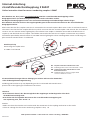
Bitte beachten Sie, dass jeweils verschiedenfarbige Kabel der stromführenden Kurzkupplung auf der
Baugruppen-Platine (z.B. Beleuchtungsbausatz) miteinander verbunden werden.
Bei Wagen ohne Baugruppen-Platine kann eine Direktverbindung verschiedenfarbiger Kabel erfolgen.
Bitte beachten Sie beim Anschluss der Kupplungskabel generell die Herstellerinformationen der anzuschließenden
Baugruppen-Platinen.
Please note that the first coupler’s red wire is connected to the second coupler’s black wire via the circuit board contacts.
The same is true for the first coupler’s black wire, which connects with the second coupler’s red wire via the circuit board
contacts. On cars without interior lighting kits, the red wire from coupler 1 should be connected to the black wire of
coupler 2, and the black wire of coupler 1 should be connected to the red wire of coupler 2. Please note any relevant
information provided by manufacturers of non-PIKO interior lighting kits when installing PIKO current conducting cou-
plers on other manufacturers’ circuit boards.
Die Kontaktbezeichnungen können abhängig von Platine und Hersteller abweichen -
siehe diesbezügliche Montageanleitung
Soldering pad locations may vary depending on the circuit board and manufacturer –
please refer to the lighting kit installation instructions.
Hinweise:
• Bitte achten Sie darauf, dass die Beweglichkeit der Kupplungen und Drehgestelle nicht durch
die Kabel beeinträchtigt wird
• Bitte halten Sie die folgenden Grenzwerte der stromführenden Kurzkupplung ein:
max. Spannung 24 V, max. Strom 1 A
Caution:
• Make sure that the wires do not interfere with the movement of the coupling mechanism or the trucks
• The max. voltage for the current conducting couplers is 24 V, 1 A
Anschlussprinzip
Connecting the coupler wires
to a PIKO circuit board:
!
!
WL - Lötpunkt für Kabel an Radschleifer links
WL - Soldering pad for wire from left wheel contact
WR - Lötpunkt für Kabel an Radschleifer rechts
bzw. Mittelschleifer
WR - Soldering pad for wire from right wheel
contact or third-rail contact
:5$
URWUHG
URWUHG
VFKZDU]EODFN
VFKZDU]EODFN
:5$
:/$
:/$
:5$
URWUHG
URWUHG
VFKZDU]EODFN
VFKZDU]EODFN
:5$
:/$
:/$
56047-90-7010
PIKO Spielwaren GmbH • Lutherstraße 30 • 96515 Sonneberg • GERMANY

Typische Anwendungsfälle:
Operating situations:
*) Bitte beachten Sie, dass der Betrieb der stromführenden Kurzkupplung nicht mit dem ersten Anwendungsfall
gemischt werden darf, da dies zu einer Beschädigung des Funktionsdecoders führen kann.
*) Caution: Do not operate a train equipped with current conducting couplers that contains both a function decoder-equipped car
and another car that is also equipped with electrical pick-ups from the rail. This will cause two different voltages to run through the
couplers and will damage the function decoder!
**) Ausgang abhängig vom verwendeten Beleuchtungsbausatz
**) Function output voltage depends on the lighting kit used
Nr. Prinzip Vorteil Spannung auf
Kupplung
Funktions-
decoder
Wagen mit
Stromab-
nahme
Kontakte für
Anschluss der
Kupplungs-
kabel
1
Abbildung 1
bzw. 2
Zug-
beleuchtung
immer
eingeschaltet
Einsparung
weiterer Mittel-
schleifer und
Radschleifer
Gleisspannung Nein Mindestes einer;
empfohlen alle
5 Wagen
WR/A, WL/A
2
Abbildung 3
bzw. 4
Zug-
beleuchtung
schaltbar
Einsparung
weiterer Mittel-
schleifer und
Radschleifer,
zentrale Schalt-
barkeit
Ausgangs-
spannung des
Funktions-
decoders
Ja, einer pro Zug Nur der Wagen
mit Funktions-
decoder*
Wagen mit
Funktions-
decoder:
F+, A3**
Andere: WR/A,
WL/A
Nr. Operational
state
Advantage Current
conducted by
couplers
Function
decoder
installed in
car
Car with
electrical
pick-up from
the rails
Contact
points for
coupler wires
1
Fig. 1
respectively 2
Train lighting is
constantly on
No need for
additional cars in
the train to have
electrical pick-up
from the rails
Couplers only
use track voltage
No At least one
car in the train
needs electrical
pick-up from
the rails; at least
one car in a five
car train needs
electrical pick-up
from the rails
WR/A, WL/A
2
Fig. 3
respectively 4
Train lighting
can be switched
on or off
No need for
additional cars in
the train to have
electrical pick-up
from the rails;
train lighting is
controlled from
a single decoder
in one car
Output voltage
of single
function decoder
located in one
car in the train
Yes, one decoder
per train
Only for the
car with the
function
decoder*
F+ and A3** on
function decoder
of car equipped
with function
decoder: all
other cars WR/A,
WL/A

URWHV.DEHO
UHGZLUH
VFKZDU]HV.DEHO
EODFNZLUH
URWHV.DEHO
UHGZLUH
VFKZDU]HV.DEHO
EODFNZLUH
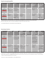
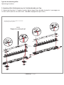
Typische Anwendungsfälle:
Operating situations:
1. Kupplung führt Gleisspannung, ohne Funktionsdecoder
1. Couplers conduct track voltage (digital or analog); no decoder present in passenger car consist
VFKZDU]HV.DEHO
EODFNZLUH
URWHV.DEHO
UHGZLUH
URWHV.DEHO
UHGZLUH
VFKZDU]HV.DEHO
EODFNZLUH
Abbildung 1 / Fig. 1
Anschlussschema Stromabnehmerkabel für DC-Betrieb
Pick-up wiring for DC operation
Kupplungskabel s. Abbildung Anschlussprinzip
Coupler wiring refer to related figure

URWHV.DEHO
UHGZLUH
VFKZDU]HV.DEHO
EODFNZLUH
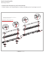
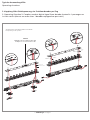
Typische Anwendungsfälle:
Operating situations:
1. Kupplung führt Gleisspannung, ohne Funktionsdecoder
1. Couplers conduct track voltage (digital or analog); no decoder present in passenger car consist
VFKZDU]HV.DEHO
EODFNZLUH
URWHV.DEHO
UHGZLUH
URWHV.DEHO
UHGZLUH
VFKZDU]HV.DEHO
EODFNZLUH
Abbildung 2 / Fig. 2
Anschlussschema Stromabnehmerkabel für AC-Betrieb
Pick-up wiring for AC operation
Kupplungskabel s. Abbildung Anschlussprinzip
Coupler wiring refer to related figure

URWHV.DEHOUHGZLUH
VFKZDU]HV.DEHOEODFNZLUH
VFKZDU]HV.DEHO
EODFNZLUH
URWHV.DEHO
UHGZLUH
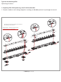
Typische Anwendungsfälle:
Operating situations:
2. Kupplung führt Schaltspannung, ein Funktionsdecoder pro Zug
2. Operating Situation 2: Couplers conduct digital signal from decoder located in 1 passenger car
in train consist (do not use more than 1 decoder-equipped car per train!)
# 56126
Multiprotokoll- Funktionsdecoder
multiprotocol function decoder
VFKZDU]HV.DEHO
EODFNZLUH
URWHV.DEHO
UHGZLUH
URWHV.DEHO
UHGZLUH
VFKZDU]HV.DEHO
EODFNZLUH
Anschlussschema Stromabnehmerkabel für DC-Betrieb
Pick-up wiring for DC operation
Abbildung 3 / Fig. 3

URWHV.DEHOUHGZLUH
VFKZDU]HV.DEHOEODFNZLUH
Typische Anwendungsfälle:
Operating situations:
2. Kupplung führt Schaltspannung, ein Funktionsdecoder pro Zug
2. Operating Situation 2: Couplers conduct digital signal from decoder located in 1 passenger car
in train consist (do not use more than 1 decoder-equipped car per train!)
# 56126
Multiprotokoll- Funktionsdecoder
multiprotocol function decoder
VFKZDU]HV.DEHO
EODFNZLUH
URWHV.DEHO
UHGZLUH
URWHV.DEHO
UHGZLUH
VFKZDU]HV.DEHO
EODFNZLUH
Anschlussschema Stromabnehmerkabel für AC-Betrieb
Pick-up wiring for AC operation
Abbildung 4 / Fig. 4
-
 1
1
-
 2
2
-
 3
3
-
 4
4
-
 5
5
-
 6
6


