Pepperl+Fuchs UB4000-F42-E6-V15 Bedienungsanleitung
- Typ
- Bedienungsanleitung

Ultraschall-Sensor
Ultrasonic sensor
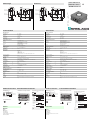
Abmessungen
Technische Daten Technical data
Elektrischer Anschluss Kurven/
Zusätzliche Informationen
Electrical connection Curves/additional information
Dimensions
UB4000-F42-E6-V15
Folientastatur
LED-Fenster
7,5
52,5
15,5
5,2
30
10
5
34
15
M12x1
80
65
80
65
16
34
A1A2
TEACH IN
MODE SET
-
Membrane keys
LED window
7.5
52.5
15.5
5.2
30
10
5
34
15
M12x1
80
65
80
65
16
34
A1A2
TEACH IN
MODE SET
Allgemeine Daten
Erfassungsbereich 200 ... 4000 mm
Einstellbereich 240 ... 4000 mm
Blindzone 0 ... 200 mm
Normmessplatte 100 mm x 100 mm
Wandlerfrequenz ca. 85 kHz
Ansprechverzug ca. 325 ms
Anzeigen/Bedienelemente
LED grün permanent grün: Power on
LED gelb 1 permanent: Schaltzustand Schaltausgang 1
blinkend: Lernfunktion
LED gelb 2 permanent: Schaltzustand Schaltausgang 2
blinkend: Lernfunktion
LED rot Normalbetrieb: "Störung"
Lernfunktion: kein Objekt erkannt
Elektrische Daten
Betriebsspannung 10 ... 30 V DC , Welligkeit 10 %SS
Leerlaufstrom I0≤ 60 mA
Ein-/Ausgang
Synchronisation bidirektional
0-Pegel: -UB...+1 V
1-Pegel: +4 V...+UB
Eingangsimpedanz: > 12 KΩ
Synchronisationsimpuls: ≥ 100 µs, Synchronisationsimpulspause: ≥ 2 ms
Synchronisationsfrequenz
Gleichtaktbetrieb ≤ 13 Hz
Multiplexbetrieb ≤ 13/n Hz, n = Anzahl der Sensoren
Ausgang
Ausgangstyp 2 Schaltausgänge pnp, Schließer/Öffner wählbar
Voreinstellung Schaltpunkt A1: 240 mm , Schaltpunkt A2: 4000 mm , breite Ultraschallkeule
Reproduzierbarkeit ≤ 0,5 % vom Schaltpunkt
Bemessungsbetriebsstrom Ie200 mA , kurzschluss-/überlastfest
Spannungsfall Ud≤ 2,5 V
Schaltfrequenz f ≤ 1,2 Hz
Abstandshysterese H 1 % des eingestellten Schaltabstandes
Temperatureinfluss ± 1 % des Endwertes
Normenkonformität
Normen EN 60947-5-2
Umgebungsbedingungen
Umgebungstemperatur -25 ... 70 °C (248 ... 343 K)
Lagertemperatur -40 ... 85 °C (233 ... 358 K)
Mechanische Daten
Schutzart IP65
Anschluss Gerätestecker V15 (M12 x 1), 5-polig
Material
Gehäuse ABS
Wandler Epoxidharz/Glashohlkugelgemisch; Schaum Polyurethan, Deckel PBT
Masse 150 g
General specifications
Sensing range 200 ... 4000 mm
Adjustment range 240 ... 4000 mm
Unusable area 0 ... 200 mm
Standard target plate 100 mm x 100 mm
Transducer frequency approx. 85 kHz
Response delay approx. 325 ms
Indicators/operating means
LED green permanently green: Power on
LED yellow 1 permanent: switching state switch output 1
flashing: TEACH-IN function
LED yellow 2 permanent: switching state switch output 2
flashing: TEACH-IN function
LED red normal operation: "fault"
TEACH-IN function: no object detected
Electrical specifications
Operating voltage 10 ... 30 V DC , ripple 10 %SS
No-load supply current I0≤ 60 m A
Input/output
Synchronisation bi-directional
0 level -UB...+1 V
1 level: +4 V...+UB
input i mpedance: > 12 KOhm
synchronisation pulse: ≥ 100 µs, synchronisation interpulse period: ≥ 2 ms
Synchronisation frequency
Common mode operation ≤ 13 Hz
Multiplex operation ≤ 13/n Hz, n = number of sensors
Output
Output type 2 switch outputs pnp, normally open/close selectable
Default setting Switch point A1: 240 mm , Switch point A2: 4000 mm , wide sound lobe
Repeat accuracy ≤ 0.5 % of switching point
Rated operational current Ie200 mA , short-circuit/overload protected
Voltage drop Ud≤ 2.5 V
Switching frequency f ≤ 1.2 Hz
Range hysteresis H 1 % of the set operating distance
Temperature influence ± 1 % of full-scale value
Standard conformity
Standards EN 60947-5-2
Ambient conditions
Ambient temperature -25 ... 70 °C (248 ... 343 K)
Storage temperature -40 ... 85 °C (233 ... 358 K)
Mechanical specifications
Protection degree IP65
Connection connector V15 (M12 x 1), 5 pin
Material
Housing ABS
Transducer epoxy resin/hollow glass sphere mixture; foam polyurethane, cover PBT
Mass 150 g
Sync.
Schaltausgang 1
Schaltausgang 2
Normsymbol/Anschluss:
(Version E6, pnp)
Adernfarben gemäß EN 60947-5-2.
+ UB
1
- UB
5
2
3
4
(BN)
(GY)
(BK)
(WH)
(BU)
U
Steckverbinder V15
2
31
45X
Y
Abstand X [m]
Charakteristische Ansprechkurve
Abstand Y [m]
breite Schallkeule
schmale Schallkeule
ebene Platte 100 mm x 100 mm
Rundstab, Ø 25 mm
0 1 2 3 4 5 6
2
1,5
1
0,5
0
-0,5
-1
-1,5
-2
A1
A2
A2
A1
A2A1
A1
A2
A1
A3
A3
A2
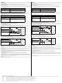
Programmierung der Schaltausgänge
Objektabstand
Betriebsart 1:
Ausgang 1
Ausgang 2
Betriebsart 2:
Ausgang 1
Ausgang 2
Betriebsart 3:
Ausgang 1
Ausgang 2
A1 , A2 : Detektion auf Objektanwesen-
heit. Beide Ausgänge verhalten sich gemäß eingestellter
Betriebsart, wenn sich ein Objekt innerhalb des
Erfassungsbereichs befindet.
Fenster und Schaltausgang:
Ausgang 1
Ausgang 1
Ausgang 2
Ausgang 2
Hinweis:
bedeutet: bedecken Sie beim Einlernen dieses
Schaltpunktes die Sensorfläche mit der Hand.
Wenn A1 = A2, arbeiten die Ausgänge so, als wäre A1 < A2
Blindzone
Prog. mit Taste A1
Prog. mit Taste A2
Montagehilfen
MH 04-3505
MHW 11
Kabeldosen *)
V15-G-2M-PVC
V15-W-2M-PUR
*) Weitere Kabeldosen finden Sie im
Abschnitt „Zubehör“.
Zubehör
A1
A2
A2
A1
A2A1
A1
A2
A1
A3
A3
A2
Switching output programmation
Object distance
Note:
means: cover transducer surface with your hand,
while programming the output.
If A1 = A2, the output work like A1 < A2
Unusable area
prog. with A1 key
prog. with A2 key
Mode 1:
output 1
output 2
Mode 2:
output 1
output 2
Mode 3:
output 1
output 2
A1 , A2 : Object presence detection.
Both outputs operate according to the selected mode,
if an object is located within the detection range.
Window and Switching point:
output 1
output 1
output 2
output 2
X
Y
Characteristic response curve
Distance X [m]
Distance Y [m]
wide sonic beam
narrow sonic beam
Flat surface 100 mm x 100 mm
Round bar, Ø 25 mm
0 1 2 3 4 5 6
2
1.5
1
0.5
0
-0.5
-1
-1.5
-2
Mounting aids
MH 04-3505
MHW 11
Cable sockets *)
V15-G-2 M-PVC
V15-W-2M-PUR
*) For additional cable sockets see section
„Accessories“.
Accessories
Standard symbol/Connections:
(version E6, pnp)
Sync.
Switch output 1
Switch output 2
Core colours in accordance with EN 60947-5-2.
+ UB
1
- UB
5
2
3
4
(BN)
(GY)
(BK)
(WH)
(BU)
U
Connector V15
2
31
45
Part. No.:
Date:
134001
12/20/2005 DIN A3 -> DIN
45-1505ADoc. No.:

Hinweise Notes
Adressen / Addresses / Adresses / Direcciónes / Indirizzi
Deutschland: Pepperl+Fuchs GmbH, Königsberger Allee 87, 68307 Mannheim, Tel. +49 (0) 621 776-1111, Fax +49 (0) 621 776-1000, fa-info@de.pepperl-fuchs.com
Great Britain: Pepperl+Fuchs (GB) Ltd., 77 Riponden Road, OLDHAM OL1 4EL, Lancashire, Tel. (161) 6 33 64 31, Telefax (161) 6 28 31 14, sales@gb.pepperl-fuchs.com
USA: Pepperl+Fuchs Inc., 1600 Enterprise Parkway, Twinsburg, Ohio 44087, Cleveland-USA, Tel. (330) 4 25 35 55, Telefax (330) 4 25 93 85, sal[email protected]rl-fuchs.com
France: Pepperl+Fuchs SARL, 12 Avenue des Tropiques - Les Ulis, 91955 COURTABOEUF CEDEX, Tel. (1) 60 92 13 13, Telefax (1) 60 92 13 25, commercial@fr.pepperl-fuchs.com
España Pepperl+Fuchs S.A., Txori-Erri Etorbidea 46, Pol. Izarza, 48150 SONDIKA (Vizcaya), Tel. (4) 4 53 50 20, Telefax (4) 4 53 51 80, s[email protected]rl-fuchs.com
Italia Pepperl+Fuchs ELCON S.r.l., Via delle Industrie, 4, 20050 MEZZAGO (Milano), Tel. (039) 6 29 21, Telefax (039) 6 29 22 40, info@it.pepperl-fuchs.com
Singapore Pepperl+Fuchs Pte Ltd., P+F Building, 18 Ayer Rajah Crescent, Singapore 139942, Tel. (65) 67 79 90 91, Telefax (65) 68 73 16 37, sales@sg.pepperl-fuchs.com
For more contact-adresses refer to the catalogue or internet: http://www.pepperl-fuchs.com
Funktionsbeschreibung
Der Sensor kann über 2 Tasten an der Gehäuseseite vollständig parametriert werden. Ein besonderes Merkmal dieses Sensors ist die
Möglichkeit die Ultraschall-Keulenbreite an die Umgebungsbedingungen am Einsatzort des Sensors anzupassen.
Einlernen der Schaltpunkte:
Mit dem Einlernen der Schaltpunkte werden die Punkte festgelegt, bei denen die Schaltausgänge ihren Zustand wechseln. Dabei bestimmt
die Anordnung der Schaltpunkte A1 < A2, bzw. A1 > A2 die Wirkungsrichtung (Öffner-/Schließerfunktion) des Schaltfensters in der Betriebsart
„Fenster + Schaltpunkt“ (siehe unten).
Das Einlernen des Schaltpunktes A2 erfolgt analog zu obiger Beschreibung mittels Taste A2.
Besonderheit bei Ausgangsfunktion „Fenster + Schaltpunkt“
Im Falle der Ausgangsfunktion (Betriebsart) „Fenster + Schaltpunkt“ (siehe unten) definieren die Schaltpunkte A1 und A2 die Fenstergrenzen
des Schaltausgangs 1.
Zusätzlich lässt sich ein 3. Schaltpunkt A3 definieren, bei dem der Schaltausgang 2 umschaltet.
Ein Einlernen der Schaltpunkte ist nur innerhalb der ersten 5 Minuten nach Zuschalten der Spannungsversorgung möglich. Sollen die
Schaltpunkte zu einem späteren Zeitpunkt verändert werden, so ist dies erst nach einem erneuten Power On möglich.
Parametrierung der Ausgangsfunktion und der Ultraschall-Keulenbreite
Wenn die Taste A1 während des Zuschaltens der Spannungsversorgung gedrückt und danach noch für 1 s gehalten wird, so geht der Sensor in die zweistufige Parame-
trierung der Betriebsmodi.
Stufe 1, Parametrierung der Ausgangsfunktion
Ausgehend von der zuletzt parametrieten Ausgangsfunktion, können durch kurzes Betätigen der Taste A2 nacheinander die möglichen
Ausgangsfunktionen angewählt werden. Diese werden durch die Blinkfolge der grünen LED angezeigt.
Mit dem Drücken der Taste A1 für 2 Sekunden wird die gewählte Ausgangsbetriebsart gespeichert, der Parametriervorgang abgeschlossen und der Sensor kehrt in den
Normalmodus zurück. Drücken Sie die Taste A1 statt dessen nur kurz, so gelangen Sie in Stufe 2 (Parametrierung der Ultraschall-Keulenbreite).
Stufe 2, Parametrierung der Ultraschall-Keulenbreite
In Stufe 2 kann die Breite der Ultraschall-Keule an die Erfordernisse der jeweiligen Applikation angepasst werden.
Ausgehend von der zuletzt parametrieten Keulenbreite, können durch kurzes Betätigen der Taste A2 nacheinander die möglichen
Keulenbreiten angewählt werden. Diese werden durch die Blinkfolge der roten LED angezeigt.
Mit dem Drücken der Taste A1 für 2 Sekunden wird die gewählte Keulenform gespeichert, der Parametriervorgang abgeschlossen und der Sensor kehrt in den Normal-
modus zurück. Drücken Sie die Taste A1 statt dessen nur kurz, so gelangen Sie zurück in Stufe 1 (Parametrierung der Ausgangsfunktion).
Wird die Parametrierung nicht binnen 5 Minuten abgeschlossen (Drücken der Taste A1 für 2 Sekunden), so bricht der Sensor den Parametriermodus mit unveränderten
Einstellungen ab.
Synchronisation
Zur Unterdrückung gegenseitiger Beeinflussung verfügt der Sensor über einen Synchronisationsanschluss. Ist dieser unbeschaltet, arbeitet
der Sensor mit einer intern erzeugten Taktrate. Eine Synchronisation mehrerer Sensoren kann auf folgende Arten erreicht werden.
Fremdsynchronisation:
Der Sensor kann durch äußeres Anlegen einer Rechteckspannung synchronisiert werden. Ein Synchronisationsimpuls am
Synchronisationseingang führt zur Durchführung eines Messzyklus. Die Impulsbreite muss größer 100 µs sein. Der Messzyklus wird mit der
fallenden Flanke gestartet. Ein Low Pegel > 1 s oder ein offener Synchronisationseingang führt zum Normalbetrieb des Sensors. Ein High
Pegel am Synchronisationseingang deaktiviert den Sensor.
Zwei Betriebsarten sind möglich
- Mehrere Sensoren werden mit dem selben Synchronisationssignal angesteuert. Die Sensoren arbeiten im Gleichtakt.
- Die Synchronisationsimpulse werden zyklisch nur jeweils einem Sensor zugeführt. Die Sensoren arbeiten im Multiplexbetrieb.
Selbstsynchronisation:
Die Synchronisationsanschlüsse von bis zu 5 Sensoren mit der Möglichkeit der Selbstsynchronisation werden miteinander verbunden. Diese
Sensoren arbeiten nach dem Einschalten der Betriebsspannung im Multiplexbetrieb. Der Ansprechverzug erhöht sich entsprechend der
Anzahl der zu synchronisierenden Sensoren. Während des Einlernens kann nicht synchronisiert werden und umgekehrt. Zum Einlernen der
Schaltpunkte müssen die Sensoren unsynchronisiert betrieben werden.
Hinweis:
Wird die Möglichkeit zur Synchronisation nicht genutzt, so ist der Synchronisationseingang mit Masse (0V) zu verbinden oder der Sensor mit
einem V1-Anschlusskabel (4-polig) zu betreiben.
Einlernen des Schaltpunktes A1 mit der Taste A1
Taste A1 > 2 s drücken Der Sensor geht in den Lernmodus für den Schaltpunkt A1
Zielobjekt in gewünschtem Abstand
positionieren
Der Sensor zeigt durch schnelles Blinken der gelben LED an, dass das
Zielobjekt erkannt wird. Bei nicht erkanntem Objekt blinkt die rote LED.
Taste A1 kurz drücken Der Sensor beendet den Einlernvorgang des Schaltpunktes A1 und speichert
diesen Wert nichtflüchtig ab. Bei unsicherem Objekt (rote LED leuchtet
unregelmäßig) ist der eingelernt Wert ungültig. Der Einlernmodus wird
verlassen.
Einlernen des Schaltpunktes A3 mit den Tasten A1 und A2
(nur Betriebsart Fenster + Schaltpunkt)
Taste A1 + A2 > 2 s drücken Der Sensor geht in den Lernmodus für den Schaltpunkt A3
Zielobjekt in gewünschtem Abstand
positionieren
Der Sensor zeigt durch schnelles Blinken der gelben LEDs an, dass das
Zielobjekt erkannt wird. Bei nicht erkanntem Objekt blinkt die rote LED.
Taste A1 kurz drücken
(Ausgang 2: Öffner)
oder
Taste A2 kurz drücken
(Ausgang 2: Schließer)
Der Sensor beendet den Einlernvorgang des Schaltpunktes A3 und speichert
diesen Wert nichtflüchtig ab.
Bei unsicherem Objekt (rote LED leuchtet unregelmäßig) ist der eingelernt
Wert ungültig. Der Einlernmodus wird verlassen.
Betriebsart Blinkfolge der grünen LED Taste A2
2 x Schließerfunktion
(default)
2 x Öffnerfunktion
2 Schaltpunkte
Schließer (Ausgang 1) +
Öffner (Ausgang 2)
Fenster (Ausgang 1) +
Schaltpunkt (Ausgang 2)
Keulenbreite Blinkfolge der roten LED Taste A2
schmale Keule
mittlere Keule
breite Keule
(default)
Pause
Pause
Pause
Pause
Pause
Pause
Pause
Functional description
The sensor can be completely parameterised using 2 keys on the side of the housing. One special feature of this sensor is the optio n o f
adapting the ultrasonic beam width to the ambient conditions at the place where the sensor is used.
Teach-in of switching points:
Teach-in of switching points is used to determine the points at which the switching outputs will change their state. In addition, the order of
switching points A1 < A2, or A1 > A2 also determines the effective direction (normally closed/open function) of the window in the output function
(operating mode) "Window + Switching point“ (see below).
The process for Teach-in of switching point A2 is similar to what was described above, using key A2.
Special feature for output function "Window + switching point“
In the case of the output function (operating mode) "Window + switching point“ (see below), switching points A1 and A2 define the window
limits of switch output 1.
A third switching point A3 can also be defined here at which switch output 2 switches.
Teach-in for switching points can only be performed within the first 5 minutes after turning on the power supply. If the switching points need to
be changed at a later time, this cannot be done until there is a new Power On.
Parameter assignment of the output function and ultrasound beam width
If you press the A1 key while the power supply is being turned on and then hold it down for 1 second, the sensor goes into the two-level parameterisation of operating modes.
Level 1, parametrisation of the output function
Pressing the A2 key briefly will cause the possible output functions to be selected one after the other (depending on the last output function to
be parameterised). The functions are indicated by a flashing sequence of the green LED.
Pressing the A1 key for 2 seconds saves the selected output operating mode. The parameter assignment process is then complete and the sensor returns to normal mode.
If you press the A1 key briefly instead, you go to Level 2 (parameter assignment of ultrasonic beam range).
Level 2, parameter assignment of ultrasonic beam width
The ultrasonic beam width can be adjusted to match the requirements of the application in Level 2.
Pressing the A2 key briefly will cause the possible beam widths to be selected one after the other (depending on the last beam width to be
parameterised). The functions are indicated by a flashing sequence of the red LED.
Pressing the A1 key for 2 seconds saves the selected type of beam width. The parameter assignment process is then complete and the sensor returns to normal mode. If
you press the A1 briefly instead, you go back to Level 1 (parameter assignment of output function).
If parameterisation is not complete within 5 minutes (pressing the A1 key for 2 seconds), the sensor interrupts parameterisation mode without changing the settings.
Synchronisation
The sensor is equipped with a synchronisation connection to suppress mutual interaction. If it is not turned on, the sensor works at an internally
generated cycle rate. Synchronisation of more than one sensor is possible in a number of different ways.
External synchronisation:
The sensor can be synchronised by the application of a square wave voltage externally. A synchronisation pulse on the synchronisation input
results in the execution of a measurement cycle. The pulse width must be greater than 100 µs. The measurement cycle must be started with
the falling signal edge. A Low level > 1 s or an open synchronisation input results in normal operation of the sensor. A High level on the
synchronisation input deactivates the sensor.
Two different operating modes are possible
- Multiple sensors can be controlled by the same synchronisation signal. The sensors work on synonymous cycle.
- Synchronisation pulses are sent cyclically to only one sensor each time. The sensors work in Multiplex mode.
Self synchronisation:
The synchronisation connections of up to 5 sensors with option for self-synchronisation are connected with each other. These sensors work
after turning on the operating voltage in Multiplex mode. The On delay increases depending on the number of sensors to be synchronised.
Synchronisation is possible during Teach-in and vice-versa. Sensors must be operated unsynchronised to perform Teach-in of switching
points.
Note:
If the option for synchronisation is not used, the synchronisation input can be connected with ground (0 V) or the sensor can be operated with
a V1 connection cable (4-pin).
Teach-in of switching point A1 with key A1
Press key A1 > 2 seconds The sensor goes into learning mode for switching point A1
Position the target object at the desired
distance
The sensor indicates by rapid flashing of the yellow LED that the target object
has been detected. If no object is detected, the red LED flashes.
Press key A1 briefly The sensor completes the Teach-in process for switching point A1 and stores
the value in permanent memory. If the object is uncertain (red LED lit
irregularly) the Teach-in value is not valid. Teach-in mode closes.
Teach-in of switching point A3 with keys A1 and A2
(only for operating mode window + switching point, see below)
Press key A1 + A2 > 2 seconds The sensor goes into learning mode for switching point A3
Position the target object at the desired
distance
The sensor indicates by rapid flashing of the yellow LEDs that the target
object has been detected. If no object is detected, the red LED flashes.
Press key A1 briefly
(output 2: normally closed)
or
Press key A2 briefly
(output 2: normally open)
The sensor completes the Teach-in process for switching point A3 and stores
the value in permanent memory.
If the object is uncertain (red LED lit irregularly) the Teach-in value is not valid.
Teach-in mode closes.
Operating mode Flashing sequence of green LED A2 key
2 x normally open function
(default)
2 x normally closed function
2 switching points
n.o. (output 1) +
n.c. (output 2)
Window (output 1) +
switching point (output 2)
Beam width Flashing sequence of red LED A2 key
Narrow beam width
Average beam width
Wide beam
(default)
Pause
Pause
Pause
Pause
Pause
Pause
Pause
-
 1
1
-
 2
2


Pepperl+Fuchs UB4000-F42-E6-V15 Bedienungsanleitung
- Typ
- Bedienungsanleitung
in anderen Sprachen
Verwandte Artikel
-
Pepperl+Fuchs UB6000-F42-E6-V15 Bedienungsanleitung
-
-
-
-
-
-
-
-