
LED 1 und LED 2 leuchten, der Schalter für Fernspeisung ist aus:
Durch vorgeschaltete Baugruppen liegt über die SAT-ZF-Eingänge eine Fern-
speisespannung an oder eine Spannungsversorgung ist am Gerät ange-
schlossen. Eine zweite Spannung liegt durch nachgeschaltete Baugruppen
über die SAT
seitig nicht, da der DC-Durchgang mit der Schalterstellung Fernspeisung aus
geblockt wird.
LED 1 and LED 2 are ON, and switch for remote power is OFF:
Due to units connected upstream, ther
e is
power on the SAT-IF
inputs or the unit is connected to an external PSU. There is also power
on the S
AT
-IF outputs due to units connected downst
r
eam. Both power
sources do not influence each other because the DC pass is blocked by
means of the remote power switch being set to
OFF
.
LED 1 und LED 2 leuchten, der Schalter für Fernspeisung ist ein:
Durch vorgeschaltete Baugruppen liegt über die SAT-ZF-Eingänge eine Fern-
speisespannung an oder eine Spannungsversorgung ist am Gerät ange-
schlossen. Mit der Schalterstellung Fernspeisung ein wird die Spannung
über die SAT-ZF-Ausgänge an nachgeschaltete Baugruppen weitergegeben.
Oder:
Durch nachgeschaltete Baugruppen liegt über die SAT-ZF-Ausgänge eine
Fernspeisespannung an. Mit der Schalterstellung Fernspeisung ein wird
die Spannung über die SAT-ZF-Eingänge an vorgeschaltete Baugruppen
weitergegeben.
► Einen Parallelbetrieb mit externem Netzteil und beidseitiger Fernspeisung
vermeiden.
LED 1 and LED 2 are on and the remote power switch is set to ON:
Due to units connected upstream, there is
power on the SAT-IF
inputs or the unit is connected to an external PSU. With the remote power
switch set to on, the units connected downstream will receive power
through the SAT-IF outputs.
Or
The unit is powered via S
AT
-IF outputs due to units connected downst
r
eam.
With the remote power switch set to on
, the power is passed
to units con-
nected upstream via the SAT-Inputs.
► Avoid parallel operation of an external PSU and bidirectional remote feed.
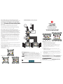
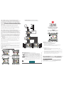
Die ECO T5 LINE/LAUNCH Verstärker können in Kombination mit folgenden
Geräten verwendet werden:
The ECO T5 LINE/LAUNCH Amplifier can be used in combinations with
following devices:
Anschlussbeispiel / Installation Example
Entsorgung / Disposal
Elektronische Geräte gehören nicht in den Hausmüll, sondern müssen
gemäß Richtlinie 2002/96/EG DES EUROPÄISCHEN PARLAMENTS UND
DES RATES vom 27. Januar 2003 über Elektro- und Elektronik-Altgeräte
fachgerecht entsorgt werden. Bitte geben Sie dieses Gerät am Ende seiner
Verwendung zur Entsorgung an den dafür vorgesehenen öffentlichen Sam-
melstellen ab.
Electronic equipment is not domestic waste – in accordance with directive
2002/96/EC OF THE EUROPEAN PARLIAMENT AND THE COUNCIL dated
27th January 2003 concerning used electrical and electronic appliances, it
must be disposed of properly. At the end of its service life, take this unit for
disposal at a designated public collection point.
Installationsanleitung
Installation Manual
Verstärker/Amplifier 20/30 dB
Type: ECO T5 LINE/LAUNCH AMP
Merkmale / Characteristics
kade mehrere Spannungsversorgungen durch vor- oder/und nachgeschaltete Baugruppen
verwendet werden, wird der DC-Durchgang mit dem Schalter Fernspeisung ein/aus
geblockt oder weitergeleitet. Dadurch wird verhindert, dass sich Spannungen der ein-
plies via units connected upstream or downstream are used in the cascade system,
the DC pass is blocked or passed using the Remote Power Switch.
This prevents interaction between different power supplies.
Änderungen vorbehalten. /Subject to change.
Abzweiger/ Taps ECO T5 1-WAY/2-WAY TAP:
High
T
V
Low
Band
V
High
Band
TER
T
V
Low
Band
V
High
Band
H
H
H
H
ECO T5: 1-Way Variable Tap
DC IN
Low
Attenuators
SAT TER
Part No: 318160Product of the Triax Group
TER
T
V
V
H
H
Tap
Outputs
30dB
25dB
20dB
15dB
12dB
30dB
12dB
25dB 15dB
20dB
TER
TMS1533-55 PSU-BS.
TMS1533-55 PSU-BS
TER 2
TER 1
TAP 2
TAP 1
SAT In
SAT Out
2
T
V
Low
Band
V
High
Band
TER In
H
H
2
T
V
Low
V
High
H
H
2
V
Low
Band
V
High
Band
H
H
2
T
V
Low
V
High
H
H
T
TER Out
ECO T5: 2-Way Variable Tap
Part No: 318161
Product of the Triax Group
SAT 2 TER 2 TER 1 SAT 1
dB
30
12
25
20
15
12
25
30
1520
dB
12
25
30
30
12
25
20
15
1520
Verstärker mit
externem Netzteil
/ amplifier with
external power
supply unit
Verteiler
/ splitter
T
V
Low
Band
V
High
Band
DC IN
T
V
Low
Band
V
High
Band
H
H
H
ECO T5 LINE AMP 20dB
Part No: 318171
Remote
Power
Product of the Triax Group
TER
TER
15dB 0dB 15dB 0dB 15dB 0dB 15dB 0dB 15dB 0dB
LNB
Power
H
power
LED
T
V
Low
Band
V
High
Band
T
V
Low
Band
V
High
Band
H
H
H
H
ECO T5: 2-Way Splitter
DC IN
Part No: 318180
Product of the Triax Group
TER
TER
T
V
Low
V
High
H
H
TER
HV V H T
GND
1
3
5
7
864
2
HV V H T
Receiver
Receiver
GND
1
3
5
7
864
2
91113
15
642 16
14
12
10
864
2
864
2
Low
Band
High
Band
TER
T516
Part No: 318101
ECO T5 Multiswitch
Product of the Triax Group
Technical spec. TER. SAT.
Frequency Range 10...790 MHz 950-2400 MHz
Insertion Loss Subscriber Outputs -1dB ±2dB -3...0dB ±2dB
Shielding Class A A
Max. Output level, IMA3@(60|35)dB 88 dBµV 102 dBµV
HV V H T
GND
1357
8642
HV V H T
Receiver
Receiver
GND
1357
8642
9111315
64
2
16
14
12108642 8642
Low
Band
High
Band
TER
T516
Part No: 318101
ECO T5 Multiswitch
Product of the Triax Group
Technical spec. TER. SAT.
Frequency Range 10...790 MHz 950-2400 MHz
Insertion Loss Subscriber Outputs -1dB ±2dB -3...0dB ±2dB
Shielding Class A A
Max. Output level, IMA3@(60|35)dB 88 dBµV 102 dBµV
power
LED
T
V
Low
Band
V
High
Band
T
V
Low
Band
V
High
Band
H
H
H
H
ECO T5: 2-Way Splitter
DC IN
Part No: 318180
Product of the Triax Group
TER
TER
T
V
Low
V
High
H
H
TER
Verteiler/Splitter ECO T5 2-WAY:
T
V
Low
Band
V
High
Band
DC IN
T
V
Low
Band
V
High
Band
H
H
H
ECO T5 LINE AMP 20dB
Part No: 318171
Remote
Power
Product of the Triax Group
TER
TER
15dB 0dB 15dB 0dB 15dB 0dB 15dB 0dB 15dB 0dB
LNB
Power
H
LNB
Power
T
V
Low
Band
V
High
Band
DC IN
T
V
Low
Band
V
High
Band
H
H
H
H
ECO T5 LAUNCH AMP 30dB
Part No: 318170
TER
TER
Product of the Triax Group
Remote
Power
Gain
Slope
-7dB 0dB -7dB 0dB -7dB 0dB -7dB 0dB -7dB 0dB
15dB 30dB 15dB 30dB 15dB 30dB 15dB 30dB 15dB 30dB
● Als Eingangs- und Stammverstärker
einsetzbar
Can
be used as a Launch or Distribution amplifier
●
Für Anlagen mit 4 SAT-ZF-Linien
zzgl. des terrestrischen Bereichs
For use on a 5 Wire trunk, 4 x SAT-IF plus terrestrial
●
Jeder Anschluss individuell im Bereich von 5 - 20/30 dB regelbar
Adjustable from 5 to 20/30 dB on each port
DC-Durchgang / DC pass:
● Reibungslose Fernspeisung über die SAT-ZF-Linien durch einen
schaltba
r
en DC-Du
r
chgang
Remote power supply over the SAT-IF lines due to
switchable DC Pass
● Geräte benötigen eine externe Spannungsversorgung oder können
ferngespeist werden, sofern zu den Ausgängen die Fernspeisung nicht
ausgeschaltet ist.*
Devices require external power supply or can be remotely powered
as long as the DC switch is not set to OFF.*
TRIAX A/S | Bjørnkærvej 3 | DK 8783 Hornsyld | Denmark
-
Gain

Bestimmungsgemäßer Gebrauch / Intended Use
Die Geräte dienen ausschließlich der Installation von Satellitenempfangs-
anlagen. Jegliche anderweitige Nutzung oder die Nichtbeachtung dieses
Anwendungshinweises hat den Verlust der Gewährleistung bzw. der Garantie
zur Folge.
The devices ar
e designed solely for the installation of IRS systems.
Any other use or failure
to comply with these instructions will void the
warranty or guarantee.
Montage- und Sicherheitshinweise
Installation and Safety Instructions
Warnung / Warning
Gefahr durch elektrische Spannung! / Danger to life from electric shock!
● Gerät nicht öffnen oder daran manipulieren.
Do not open or tamper with the unit.
● Bei Arbeiten an der Anlage immer Netzstecker aus der Steckdose
ziehen.
When working on the system, always unplug the mains plug from
the socket.
● Um das Gerät allseitig ein Fr
● Gerät nicht an der Decke montieren.
Do not mount the units on top of each other.
● Um das Gerät eine freie Luftzirkulation sicherstellen.
Ensure free circulation of air t
o dissipate
the heat emitted by the unit.
●
Per
● Auf das Netzgerät keine mit Flüssigkeit gefüllten Gegenstände
stellen.
Do not place any liquid-filled items on top of th
e products.
.
● Das Netzgerät nicht Tropf- oder Spritzwasser aussetzen.
Do not expose the
products to dripping or
s
p
l
as
hin
g
wa
t
e
r.
● Sicherstellen, dass der Netzstecker ohne Schwierigkeiten zugäng-
lich und benutzbar ist.
Make sure that the power supply unit is easily accessible and operable.
●
Netzstecker ziehen, um das Gerät sicher vom Netz zu trennen.
Switch off the mains supply before unplugging the unit.
Achtung / Notice
Gefahr von Geräteschäden! / Risk of material damage!
● Gerät nur in trockenen Innenräumen und nicht auf oder an leicht
entzündlichen Materialien montieren.
Install the unit only in dry areas indoors. Do not install on or
against highly combustible materials.
● Gerät mit einer Potenzial-Ausgleichsleitung versehen
2
).
Make sure that the unit is provided with an earthing wire (Cu, at
2
).
● Sicherheitsbestimmungen der jeweils aktuellen Normen
Comply with the safety regulations set out in the current
● Befestigungsmittel: Holzschrauben, Ø max. 4,5 mm
Fixings: wood scr
● V
according to
● Nicht benutzte Teilnehmerausgänge mit 75-Ω-Widerständen
abschließen.
.
●
V
o
r In
bet
r
ieb
n
a
hm
e
die
An
lag
e
au
f
evt
l. K
u
rz
sc
hl
üsse
de
r
Koaxia
l
-
k
abe
l
überprüfen. Darauf achten, dass die Eingangspegel der S
AT
-
Ebenen möglichst gleich hoch sind. Eine Powe
r
-LED zeigt den
Betrieb an. Die St
r
omzufuhr kont
r
ollie
r
en, wenn die Powe
r-LED
nicht leuchtet.
Befo
r
e commissioning, make su
r
e the
r
e is no short circuit in the
coaxial cable. Ensu
r
e that the input levels a
r
e the same, if pos-
sible. A power LED shows the operation mode. If it is not on,
check the power source.
●
Nur Koaxialkabel mit einem maximalen Innenleiterdu
r
chmesser
Only use coaxial cables with the max. Ø of the inner conductor of
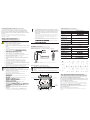
Installation /
Installation
F
-
Ste
cker
m
ontie
r
e
n
/
Connecting the F-type Connector
Abb. 2: F-Stecker montie
r
en /
Fig. 2: Connecting the F-type connector
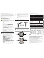
Gerät anschließen / Connecting the unit
Anschlüsse gemäß dem Aufdruck installieren.
Connect according to the sticker on the device.
Elektrische Installationen nur durch geschultes Fachpersonal durchführen
lassen.
Make sure electrical installations are performed by qualified personnel.
S
AT
-ZF-Eingänge
Input S
AT
-IF lines
T
er
r
. Eingang
Input ter
r
.
Spannungsversorgung 15 V DC
T
er
r
. Ausgang
Output ter
r
.
SAT-Ausgänge
Output SAT
Fe
r
nspeisung an/aus
Remote power on/off
Ground
Power supply 15 V DC
Technische Daten / Technical Data
LED – Signalisierungszustände und Fernspeisefälle
LED – Signal Status and Remote Power Supply operation
LED 1 leuchtet, der Schalter für Fernspeisung ist aus:
Durch vorgeschaltete Baugruppen liegt über die SAT-ZF-Ausgänge eine Fern-
speisespannung an oder am Gerät selbst ist eine Spannungsversorung ange-
schlossen (TMS1533-55 PSU-BS).
LED 1 is on and remote power switch is off:
Due to units connected upstream, there is a remote power on the SAT-IF
inputs or the unit is connected to an external PSU (TMS1533-55 PSU-BS).
LED 2 leuchtet, der Schalter für Fernspeisung ist aus:
Durch nachgeschaltete Baugruppen liegt über die SAT-ZF-Ausgänge eine
Fernspeisespannung an.
LED 2 is on and the remote power switch is off:
Due to units connected downstream, there is
r
emo
t
e
po
w
e
r on the SAT-IF
outputs.
Überstand /
excess length
(Gefahr des Überdrehens)/
(danger of overwinding)
fr
ee of burrs
T
V
Low
Band
V
High
Band
DC IN
T
V
Low
Band
V
High
Band
H
H
H
ECO T5 LINE AMP 20dB
Part No: 318171
Remote
Power
Product of the Triax Group
TER
TER
15dB 0dB 15dB 0dB 15dB 0dB 15dB 0dB 15dB 0dB
LNB
Power
H
Verstärkungsregler
Gain control
Eingänge/Inputs
Ausgänge/Outputs
Eingangs- und Ausgangsimpedanz
Input and output impedance
75 ohm F-Female
Frequenzbereich/Frequency range SAT
Frequenzbereich/Frequency range TER
Verstärkung SAT/
Gain SAT
Verstärkung TER/Gain TER
Isolation H/V
Preemphase/Slope
Ausgangspegel SAT
Output level SAT
Ausgangspegel TER
Output level TER
Rauschmaß/Noise figure
Return loss
Externes Netzteil
External PSU
Stromverbrauch/Current consumption
Gewicht/Weight
Betriebstemperaturbereich
Operating temperature range
DC-Anschlusstyp
DC Connector type
Typ
ECO T5 Line Amp 20 dB ECO T5 Launch Amp 30 dB
40 - 790 MHz
950 - 2200 MHz
(control range)
(control range)
30 dB
30 dB
20 dB
20 dB
3 dB
112 dBµV 118 dBµV
105 dBµV 110 dBµV
> 10 dB
7 dB5 dB
TMS1533-55 PSU-BS
220 mA 300 mA
Dimensions (L x W x H)
160x120x62 mm 160x140x62 mm
~ 350 g ~ 400 g
-20...70 °C
DC-Netzteilbuchse 5,5/2,1
DC-jack 5,5/2,1
- 20 °C bis 70 °C
- 20 °C bis 70 °C
3...10 dB
T
er
r
. Ausgang
Output ter
r
.
SAT-Ausgänge
Output SAT
Spannungsversorgung 15 V DC
Power supply 15 V DC
S
AT
-ZF-Eingänge
Input S
AT
-IF lines
T
er
r
. Eingang
Input ter
r
.
Ground
Fe
r
nspeisung an/aus
Remote power on/off
Verstärkungsregler
Gain control
Steigungsregler
Slope control
T
V
Low
Band
V
High
Band
DC IN
T
V
Low
Band
V
High
Band
H
H
H
H
ECO T5 LAUNCH AMP 30dB
Part No: 318170
TER
TER
Product of the Triax Group
Remote
Power
Gain
Slope
-7dB 0dB -7dB 0dB -7dB 0dB -7dB 0dB -7dB 0dB
15dB 30dB 15dB 30dB 15dB 30dB 15dB 30dB 15dB 30dB
LNB
Power
Gain

LED 1 und LED 2 leuchten, der Schalter für Fernspeisung ist aus:
Durch vorgeschaltete Baugruppen liegt über die SAT-ZF-Eingänge eine Fern-
speisespannung an oder eine Spannungsversorgung ist am Gerät ange-
schlossen. Eine zweite Spannung liegt durch nachgeschaltete Baugruppen
über die SAT
seitig nicht, da der DC-Durchgang mit der Schalterstellung Fernspeisung aus
geblockt wird.
LED 1 and LED 2 are ON, and switch for remote power is OFF:
Due to units connected upstream, there is
power on the SAT-IF
inputs or the unit is connected to an external PSU. There is also power
on the S
AT
-IF outputs due to units connected downst
r
eam. Both power
sources do not influence each other because the DC pass is blocked by
means of the remote power switch set to OFF.
LED 1 und LED 2 leuchten, der Schalter für Fernspeisung ist ein:
Durch vorgeschaltete Baugruppen liegt über die SAT-ZF-Eingänge eine Fern-
speisespannung an oder eine Spannungsversorgung ist am Gerät ange-
schlossen. Mit der Schalterstellung Fernspeisung ein wird die Spannung
über die SAT-ZF-Ausgänge an nachgeschaltete Baugruppen weitergegeben.
Oder:
Durch nachgeschaltete Baugruppen liegt über die SAT-ZF-Ausgänge eine
Fernspeisespannung an. Mit der Schalterstellung Fernspeisung ein wird
die Spannung über die SAT-ZF-Eingänge an vorgeschaltete Baugruppen
weitergegeben.
► Einen Parallelbetrieb mit externem Netzteil und beidseitiger Fernspeisung
vermeiden.
LED 1 and LED 2 are ON, and the switch for R
emote
P
ower is ON:
Due to units connected upstream, there is
power on the SAT-IF
inputs or the unit is connected to an external PSU. With the remote power
switch set to on, the units connected downstream will receive power
through the SAT-IF outputs.
Or
The unit is powered via S
AT
-IF outputs due to units connected downst
r
eam.
With the remote power switch set to on, the power is passed
to units con-
nected upstream via the S
AT
-IF inputs.
► Avoid parallel operation of an external PSU and bidirectional
r
emote feed.
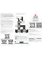
Die ECO T5 1-Way/2-Way Abzweiger können in Kombination mit folgenden
Geräten verwendet werden:
The ECO T5 1-Way/2-Way Taps can be used in combinations with
following devices:
Anschlussbeispiel / Installation Example
Entsorgung / Disposal
Elektronische Geräte gehören nicht in den Hausmüll, sondern müssen
gemäß Richtlinie 2002/96/EG DES EUROPÄISCHEN PARLAMENTS UND
DES RATES vom 27. Januar 2003 über Elektro- und Elektronik-Altgeräte
fachgerecht entsorgt werden. Bitte geben Sie dieses Gerät am Ende seiner
Verwendung zur Entsorgung an den dafür vorgesehenen öffentlichen Sam-
melstellen ab.
Electronic equipment is not domestic waste – in accordance with directive
2002/96/EC OF THE EUROPEAN PARLIAMENT AND THE COUNCIL dated
27th January 2003 concerning used electrical and electronic appliances, it
must be disposed of properly. At the end of its service life, take this unit for
disposal at a designated public collection point.
Installationsanleitung
Installation Manual
Abzweiger/Taps
Type: ECO T5 1-Way/2-Way Tap
Merkmale / Characteristics
kade meh
r
e
r
e Spannungsverso
r
gungen du
r
ch vo
r
- oder/und nachgeschaltete Baugruppen
verwendet we
r
den, wi
r
d der DC-Du
r
chgang mit dem Schalte
r
Fe
r
nspeisung ein/aus
geblockt oder weite
r
geleitet. Dadu
r
ch wi
r
d verhindert, dass sich Spannungen der ein-
Änderungen vorbehalten. /Subject to change.
TMS1533-55 PSU-BS.
Verstärker mit
externem Netzteil
/ amplifier with
external power
supply unit
Abzweiger
/ Tap
T
V
Low
Band
V
High
Band
DC IN
T
V
Low
Band
V
High
Band
H
H
H
ECO T5 LINE AMP 20dB
Part No: 318171
Remote
Power
Product of the Triax Group
TER
TER
15dB 0dB 15dB 0dB 15dB 0dB 15dB 0dB 15dB 0dB
LNB
Power
H
HV V H T
GND
1
3
5
7
864
2
HV V H T
Receiver
Receiver
GND
1
3
5
7
864
2
91113
15
642 16
14
12
10
864
2
864
2
Low
Band
High
Band
TER
T516
Part No: 318101
ECO T5 Multiswitch
Product of the Triax Group
Technical spec. TER. SAT.
Frequency Range 10...790 MHz 950-2400 MHz
Insertion Loss Subscriber Outputs -1dB ±2dB -3...0dB ±2dB
Shielding Class A A
Max. Output level, IMA3@(60|35)dB 88 dBµV 102 dBµV
HV V H T
GND
1357
8642
HV V H T
Receiver
Receiver
GND
1357
8642
9111315
64
2
16
14
12108642 8642
Low
Band
High
Band
TER
T516
Part No: 318101
ECO T5 Multiswitch
Product of the Triax Group
Technical spec. TER. SAT.
Frequency Range 10...790 MHz 950-2400 MHz
Insertion Loss Subscriber Outputs -1dB ±2dB -3...0dB ±2dB
Shielding Class A A
Max. Output level, IMA3@(60|35)dB 88 dBµV 102 dBµV
power
LED
T
V
Low
Band
V
High
Band
T
V
Low
Band
V
High
Band
H
H
H
H
ECO T5: 2-Way Splitter
DC IN
Part No: 318180
Product of the Triax Group
TER
TER
T
V
Low
V
High
H
H
TER
Verteiler/Splitter ECO T5 2-WAY:
●
Als Eingangs- und Stammabzweiger einsetzbar
C
a
n
be
used
as
in
p
u
t
o
r
t
r
u
nk
Tap
●
Für Anlagen mit 4 SAT-ZF Linien
zzgl. des ter
r
estrischen Be
r
eichs
For use on a 5 wire trunk, 4 SAT-IF lines plus terrestrial
DC-Du
r
chgang
/ DC pass:
●
Reibungslose Fernspeisung über die SAT-ZF-Linien durch
einen schaltba
r
en DC-Du
r
chgang
High
T
V
Low
Band
V
High
Band
TER
T
V
Low
Band
V
High
Band
H
H
H
H
ECO T5: 1-Way Variable Tap
DC IN
Low
Attenuators
SAT TER
Part No: 318160
Product of the Triax Group
TER
T
V
V
H
H
Tap
Outputs
30dB
25dB
20dB
15dB
12dB
30dB
12dB
25dB 15dB
20dB
TER
TER 2
TER 1
T
AP 2
TAP 1
SAT In
SAT Out
2
T
V
Low
Band
V
High
Band
TER In
H
H
2
T
V
Low
V
High
H
H
2
V
Low
Band
V
High
Band
H
H
2
T
V
Low
V
High
H
H
T
TER Out
ECO T5: 2-Way Variable Tap
Part No: 318161
Product of the Triax Group
SAT 2 TER 2 TER 1 SAT 1
dB
30
12
25
20
15
12
25
30
1520
dB
12
25
30
30
12
25
20
15 1520
T
V
Low
Band
V
High
Band
DC IN
T
V
Low
Band
V
High
Band
H
H
H
ECO T5 LINE AMP 20dB
Part No: 318171
Remote
Power
Product of the Triax Group
TER
TER
15dB 0dB 15dB 0dB 15dB 0dB 15dB 0dB 15dB 0dB
LNB
Power
H
LNB
Power
T
V
Low
Band
V
High
Band
DC IN
T
V
Low
Band
V
High
Band
H
H
H
H
ECO T5 LAUNCH AMP 30dB
Part No: 318170
TER
TER
Product of the Triax Group
Remote
Power
Gain
Slope
-7dB 0dB -7dB 0dB -7dB 0dB -7dB 0dB -7dB 0dB
15dB 30dB 15dB 30dB 15dB 30dB 15dB 30dB 15dB 30dB
High
T
V
Low
Band
V
High
Band
TER
T
V
Low
Band
V
High
Band
H
H
H
H
ECO T5: 1-Way Variable Tap
DC IN
Low
Attenuators
SAT TER
Part No: 318160
Product of the Triax Group
TER
T
V
V
H
H
Tap
Outputs
30dB
25dB
20dB
15dB
12dB
30dB
12dB
25dB 15dB
20dB
TER
TRIAX A/S | Bjørnkærvej 3 | DK 8783 Hornsyld | Denmark
-
Remote power supply over the SAT-IF lines due to
switchable DC Pass
plies via units connected upst
r
eam or downst
r
eam a
r
e used in the cascade system,
the DC pass is blocked or passed using the Remote Power Switch.
This prevents interaction between different power supplies.
TMS1533-55 PSU-BS

Bestimmungsgemäßer Gebrauch / Intended Use
Die Geräte dienen ausschließlich der Installation von Satellitenempfangs-
anlagen. Jegliche anderweitige Nutzung oder die Nichtbeachtung dieses
Anwendungshinweises hat den Verlust der Gewährleistung bzw. der Garantie
zur Folge.
Montage- und Sicherheitshinweise
Installation and Safety Instructions
Warnung / Warning
Gefahr durch elektrische Spannung! / Danger to life from electric shock!
● Gerät nicht öffnen oder daran manipulieren.
Do not open or tamper with the unit.
● Bei Arbeiten an der Anlage immer Netzstecker aus der Steckdose
ziehen.
When working on the system, always unplug the mains plug from
the socket.
● Um das Gerät allseitig ein Fr
● Gerät nicht an der Decke montieren.
● Um das Gerät eine freie Luftzirkulation sicherstellen.
●
Per
● Auf das Netzgerät keine mit Flüssigkeit gefüllten Gegenstände
stellen.
.
● Das Netzgerät nicht Tropf- oder Spritzwasser aussetzen.
.
● Sicherstellen, dass der Netzstecker ohne Schwierigkeiten zugäng-
lich und benutzbar ist.
Make sure that the power supply unit is easily accessible and operable.
●
Netzstecker ziehen, um das Gerät sicher vom Netz zu trennen.
Switch off the mains supply before unplugging the unit.
Achtung / Notice
Gefahr von Geräteschäden! / Risk of material damage!
● Gerät nur in trockenen Innenräumen und nicht auf oder an leicht
entzündlichen Materialien montieren.
Install the unit only in dry areas indoors. Do not install on or
against highly combustible materials.
● Gerät mit einer Potenzial-Ausgleichsleitung versehen
2
).
Make sure that the unit is provided with an earthing wire (Cu, at
2
).
● Sicherheitsbestimmungen der jeweils aktuellen Normen
Comply with the safety regulations set out in the current
● Befestigungsmittel: Holzschrauben, Ø max. 4,5 mm
Fixings: wood scr
● V
according to
● Nicht benutzte Teilnehmerausgänge mit 75-Ω-Widerständen
abschließen.
● Vor Inbetriebnahme die Anlage auf evtl. Kurzschlüsse der Koaxial-
kabel überprüfen. Darauf achten, dass die Eingangspegel der SAT-
Ebenen möglichst gleich hoch sind. Eine Power-LED zeigt den
Betrieb an. Die Stromzufuhr kontrollieren, wenn die Power-LED
nicht leuchtet.
Before commissioning, make sure there is no short circuit in the
coaxial cable. Ensure that the input levels are the same, if pos-
sible. A power LED shows the operation mode. If it is not on,
check the power source.
● Nur Koaxialkabel mit einem maximalen Innenleiterdurchmesser
Only use coaxial cables with the max. Ø of the inner conductor of
Installation / Installation
F-Stecker montieren / Connecting the F-type Connector
Abb. 2: F-Stecker montieren / Fig. 2: Connecting the F-type connector
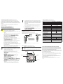
Gerät anschließen / Connecting the unit
Anschlüsse gemäß dem Aufdruck installieren.
Connect according to the sticker on the device.
Elektrische Installationen nur durch geschultes Fachpersonal durchführen
lassen.
Make sure electrical installations are performed by qualified personnel.
S
AT
-ZF-Eingänge
Input S
AT
-IF lines
T
er
r
. Eingang
Input ter
r
.
Spannungsversorgung 15 V DC
T
er
r
. Ausgang
Output ter
r.
SAT-Durchgang
SAT throughput
Ground
Power supply 15 V DC
Technische Daten / Technical Data
Überstand /
excess length
(Gefahr des Überdrehens)/
(danger of overwinding)
free of burrs
Abzweigausgänge
Tap outputs
Eingänge/Inputs
Ausgänge/Outputs
Eingangs- und Ausgangsimpedanz
Input and output impedance
75 ohm F-Female
Frequenzbereich/Frequency range SAT
Frequenzbereich/Frequency range TER
Typ
ECO T5 1-Way Tap ECO T5 2-Way Tap
10 - 790 MHz
950 - 2400 MHz
- 20 °C bis 70 °C
- 20 °C bis 70 °C
Abzweigdämpfung/Tap loss SAT
Abzweigdämpfung/Tap loss TER
Durchgangsdämpfung SAT
Through loss SAT
Durchgangsdämpfung TER
Through loss TER
ssdämpfung SAT
Return loss SAT
Externes Netzteil
External PSU
Gewicht/Weight
Betriebstemperaturbereich
Operating temperature range
DC-Anschlusstyp
DC Connector type
Abmessungen L x B x H
Dimensions L x W x H
SAT
Ausgänge/Outputs TER
4 x line, 4 x tap 4 x line, 2 x 4 tap
1 x line, 1 x tap 1 x line, 2 x 1 tap
15...12 dB ± 1 dB
12 dB ± 1 dB
Attenuator SAT/TER 0...18 dB
1...2 dB ±1 dB 2...4 dB ±1 dB
1 dB ±0,5 dB 3,5 dB ±1 dB
> 10 dB
ssdämpfung TER
Return loss TER
> 10 dB
TMS1533-55 PSU-BS
160x140x62 mm 160x140x62 mm
~ 400 g ~ 400 g
- 20...70 °C
DC-Netzteilbuchse 5,5/2,1 mm
DC Jack 5,5/2,1 mm
High
T
V
Low
Band
V
High
Band
TER
T
V
Low
Band
V
High
Band
H
H
H
H
ECO T5: 1-Way Variable Tap
DC IN
Low
Attenuators
SAT TER
Part No: 318160
Product of the Triax Group
TER
T
V
V
H
H
Tap
Outputs
30dB
25dB
20dB
15dB
12dB
30dB
12dB
25dB 15dB
20dB
TER
output power on/off
tap power on/off
input power on/off
Terr. Ausgang
Output terr.
The devices are designed solely for the installation of IRS systems.
Any other use or failure
to comply with these instructions will void the
warranty or guarantee.
Do not mount the units on top of each other.
Ensure free circulation of air t
o dissipate
the heat emitted by the unit.
Do not place any liquid-filled items on top of th
e products.
Do not expose the
products to dripping or
s
p
l
as
hin
g
wa
t
e
r.
LED – Signalisierungszustände und Fe
r
nspeisefälle
LED – Signal Status and Remote Power Supply operation
LED 1 leuchtet, der Schalter für Fe
r
nspeisung ist aus:
Du
r
ch vo
r
geschaltete Baugruppen liegt über die S
AT
-ZF-Ausgänge eine Fe
rn-
speisespannung an oder am Gerät selbst ist eine Spannungsversorung ange-
schlossen (TMS1533-55 PSU-BS).
LED 1 is on and remote power switch is off:
Due to units connected upst
r
eam, the
r
e is a
r
emote power on the SAT-IF
inputs or the unit is connected to an exte
r
nal PSU (TMS1533-55 PSU-BS).
LED 2 leuchtet, der Schalter für Fe
r
nspeisung ist aus:
Du
r
ch nachgeschaltete Baugruppen liegt über die S
AT
-ZF-Ausgänge eine
Fe
r
nspeisespannung an.
LED 2 is on and the remote power switch is off:
D
ue
t
o
u
ni
t
s
co
n
nected
do
wn
s
t
r
ea
m
,
t
h
e
r
e
i
s
r
emo
t
e
po
w
e
r on the SAT-IF
out
p
u
t
s
.

Der ECO T5 2-Way Splitter kann in Kombination mit folgenden Geräten
verwendet werden:
The ECO T5 2-Way Splitter can be used in combinations with following
devices:
Input-/T
Anschlussbeispiel / Installation Example
Entsorgung / Disposal
Elektronische Geräte gehören nicht in den Hausmüll, sondern müssen
gemäß Richtlinie 2002/96/EG DES EUROPÄISCHEN PARLAMENTS UND
DES RATES vom 27. Januar 2003 über Elektro- und Elektronik-Altgeräte
fachgerecht entsorgt werden. Bitte geben Sie dieses Gerät am Ende seiner
Verwendung zur Entsorgung an den dafür vorgesehenen öffentlichen Sam-
melstellen ab.
Electronic equipment is not domestic waste – in accordance with directive
2002/96/EC OF THE EUROPEAN PARLIAMENT AND THE COUNCIL dated
27th January 2003 concerning used electrical and electronic appliances, it
must be disposed of properly. At the end of its service life, take this unit for
disposal at a designated public collection point.
Installationsanleitung
Installation Manual
Splitter
Type: ECO T5 2-WAY Splitter
Merkmale / Characteristics
● Zur Erweiterung der Triax Satellitenanlagen.
For extension of
Triax IRS systems.
●
Für Anlagen mit 4 SAT-ZF Linien zzgl. des terrestrischen Bereich
DC-Durchgang / DC pass:
● Reibungslose Fer
nspeisung über die SAT-ZF-Linien durch einen
schaltbaren DC-Durchgang
● keine Spannungsversorgung notwendig, es kann optional zur Fernspei-
sung ander
er Elemente ein Netzteil angeschlossen we
r
den.*
No power supply needed, however, it is possible to connect an external
power supply unit for r
emote power supply of other units
kade mehrere Spannungsversorgungen durch vor- oder/und nachgeschaltete Baugruppen
verwendet werden, wird der DC-Durchgang mit dem Schalter Fernspeisung ein/aus
geblockt oder weitergeleitet. Dadurch wird verhindert, dass sich Spannungen der ein-
Änderungen vorbehalten. /Subject to change.
Abzweiger/ Taps ECO T5 1-WAY/2-WAY TAP:
T
V
Low
Band
V
High
Band
DC IN
T
V
Low
Band
V
High
Band
H
H
H
ECO T5 LINE AMP 20dB
Part No: 318171
Remote
Power
Product of the Triax Group
TER
TER
15dB 0dB 15dB 0dB 15dB 0dB 15dB 0dB 15dB 0dB
LNB
Power
H
LNB
Power
T
V
Low
Band
V
High
Band
DC IN
T
V
Low
Band
V
High
Band
H
H
H
H
ECO T5 LAUNCH AMP 30dB
Part No: 318170
TER
TER
Product of the Triax Group
Remote
Power
Gain
Slope
-7dB 0dB -7dB 0dB -7dB 0dB -7dB 0dB -7dB 0dB
15dB 30dB 15dB 30dB 15dB 30dB 15dB 30dB 15dB 30dB
High
T
V
Low
Band
V
High
Band
TER
T
V
Low
Band
V
High
Band
H
H
H
H
ECO T5: 1-Way Variable Tap
DC IN
Low
Attenuators
SAT TER
Part No: 318160Product of the Triax Group
TER
T
V
V
H
H
Tap
Outputs
30dB
25dB
20dB
15dB
12dB
30dB
12dB
25dB 15dB
20dB
TER
TMS1533-55 PSU-BS.
TER 2
TER 1
TAP 2
TAP 1
SAT In
SAT Out
2
T
V
Low
Band
V
High
Band
TER In
H
H
2
T
V
Low
V
High
H
H
2
V
Low
Band
V
High
Band
H
H
2
T
V
Low
V
High
H
H
T
TER Out
ECO T5: 2-Way Variable Tap
Part No: 318161
Product of the Triax Group
SAT 2 TER 2 TER 1 SAT 1
dB
30
12
25
20
15
12
25
30
1520
dB
12
25
30
30
12
25
20
15
1520
Verstärker mit
externem Netzteil
/ amplifier with
external power
supply unit
Verteiler
/ splitter
T
V
Low
Band
V
High
Band
DC IN
T
V
Low
Band
V
High
Band
H
H
H
ECO T5 LINE AMP 20dB
Part No: 318171
Remote
Power
Product of the Triax Group
TER
TER
15dB 0dB 15dB 0dB 15dB 0dB 15dB 0dB 15dB 0dB
LNB
Power
H
power
LED
T
V
Low
Band
V
High
Band
T
V
Low
Band
V
High
Band
H
H
H
H
ECO T5: 2-Way Splitter
DC IN
Part No: 318180
Product of the Triax Group
TER
TER
T
V
Low
V
High
H
H
TER
HV V H T
GND
1357
8642
HV V H T
Receiver
Receiver
GND
1357
8642
9111315
642 161412108642 8642
Low
Band
High
Band
TER
T516
Part No: 318101
ECO T5 Multiswitch
Product of the Triax Group
Technical spec. TER. SAT.
Frequency Range 10...790 MHz 950-2400 MHz
Insertion Loss Subscriber Outputs -1dB ±2dB -3...0dB ±2dB
Shielding Class A A
Max. Output level, IMA3@(60|35)dB 88 dBµV 102 dBµV
HV V H T
GND
1357
8642
HV V H T
Receiver
Receiver
GND
1357
8642
9111315
642 161412108642 8642
Low
Band
High
Band
TER
T516
Part No: 318101
ECO T5 Multiswitch
Product of the Triax Group
Technical spec. TER. SAT.
Frequency Range 10...790 MHz 950-2400 MHz
Insertion Loss Subscriber Outputs -1dB ±2dB -3...0dB ±2dB
Shielding Class A A
Max. Output level, IMA3@(60|35)dB 88 dBµV 102 dBµV
power
LED
T
V
Low
Band
V
High
Band
T
V
Low
Band
V
High
Band
H
H
H
H
ECO T5: 2-Way Splitter
DC IN
Part No: 318180
Product of the Triax Group
TER
TER
T
V
Low
V
High
H
H
TER
TRIAX A/S | Bjørnkærvej 3 | DK
-
8783 Hornsyld | Denmark
LED 1 und LED 2 leuchten, der Schalter für Fernspeisung ist aus:
Durch vorgeschaltete Baugruppen liegt über die SAT-ZF-Eingänge eine Fern-
speisespannung an oder eine Spannungsversorgung ist am Gerät ange-
schlossen. Eine zweite Spannung liegt durch nachgeschaltete Baugruppen
über die SAT
seitig nicht, da der DC-Durchgang mit der Schalterstellung Fernspeisung aus
geblockt wird.
LED 1 and LED 2 are ON, and switch for remote power is OFF:
Due to units connected upstream, ther
e is
power on the SAT-IF
inputs or the unit is connected to an external PSU. Ther
e is also power
on the S
AT
-IF outputs due to units connected downst
r
eam. Both power
sources do not influence each other because the DC pass is blocked by
means of the r
emote power switch being set to
OFF
.
LED 1 und LED 2 leuchten, der Schalter für Fernspeisung ist ein:
Durch vorgeschaltete Baugruppen liegt über die SAT-ZF-Eingänge eine Fern-
speisespannung an oder eine Spannungsversorgung ist am Gerät ange-
schlossen. Mit der Schalterstellung Fernspeisung ein wird die Spannung
über die SAT-ZF-Ausgänge an nachgeschaltete Baugruppen weitergegeben.
Oder:
Durch nachgeschaltete Baugruppen liegt über die SAT-ZF-Ausgänge eine
Fernspeisespannung an. Mit der Schalterstellung Fernspeisung ein wird
die Spannung über die SAT-ZF-Eingänge an vorgeschaltete Baugruppen
weitergegeben.
► Einen Parallelbetrieb mit externem Netzteil und beidseitiger Fernspeisung
vermeiden.
LED 1 and LED 2 are on and the remote power switch is set to ON:
Due to units connected upstream, ther
e is
power on the SAT-IF
inputs or the unit is connected to an external PSU. With the remote power
switch set to on, the units connected downstream will r
eceive power
through the SAT-IF outputs.
Or
The unit is power
ed via S
AT
-IF outputs due to units connected downst
r
eam.
With the remote power switch set to on
, the power is passed
to units con-
nected upstr
eam via the SAT-Inputs.
► Avoid parallel operation of an exter
nal PSU and bidirectional remote feed.
For use on a 5 Wire trunk, 4 x SAT-IF plus terrestrial
Remote power supply over the SAT-IF lines due to
switchable DC Pass
plies via units connected upst
r
eam or downst
r
eam a
r
e used in the cascade system,
the DC pass is blocked or passed using the Remote Power Switch.
This prevents interaction between different power supplies.
TMS1533-55 PSU-BS

Bestimmungsgemäßer Gebrauch / Intended Use
Die Geräte dienen ausschließlich der Installation von Satellitenempfangs-
anlagen. Jegliche anderweitige Nutzung oder die Nichtbeachtung dieses
Anwendungshinweises hat den Verlust der Gewährleistung bzw. der Garantie
zur Folge.
Montage- und Sicherheitshinweise
Installation and Safety Instructions
Warnung / Warning
Gefahr durch elektrische Spannung! / Danger to life from electric shock!
● Gerät nicht öffnen oder daran manipulieren.
Do not open or tamper with the unit.
● Bei Arbeiten an der Anlage immer Netzstecker aus der Steckdose
ziehen.
When working on the system, always unplug the mains plug from
the socket.
● Um das Gerät allseitig ein Fr
● Gerät nicht an der Decke montieren.
● Um das Gerät eine freie Luftzirkulation sicherstellen.
.
●
● Auf das Netzgerät keine mit Flüssigkeit gefüllten Gegenstände
stellen.
● Das Netzgerät nicht Tropf- oder Spritzwasser aussetzen.
.
● Sicherstellen, dass der Netzstecker ohne Schwierigkeiten zugäng-
lich und benutzbar ist.
Make sure that the power supply unit is easily accessible and operable.
●
Netzstecker ziehen, um das Gerät sicher vom Netz zu trennen.
Achtung / Notice
Gefahr von Geräteschäden! / Risk of material damage!
● Gerät nur in trockenen Innenräumen und nicht auf oder an leicht
entzündlichen Materialien montieren.
Install the unit only in dry areas indoors. Do not install on or
against highly combustible materials.
● Gerät mit einer Potenzial-Ausgleichsleitung versehen
2
).
Make sure that the unit is provided with an earthing wire (Cu, at
2
).
● Sicherheitsbestimmungen der jeweils aktuellen Normen
Comply with the safety regulations set out in the current
● Befestigungsmittel: Holzschrauben, Ø max. 4,5 mm
Fixings: wood scr
● V
according to
● Nicht benutzte Teilnehmerausgänge mit 75-Ω-Widerständen
abschließen.
●
V
o
r In
betrieb
n
ah
m
e
die
An
lage
au
f
evtl
. K
u
r
zsc
hl
üsse
de
r
Koaxia
l
-
kabe
l
überprüfen. Darauf achten, dass die Eingangspegel der S
AT
-
Ebenen möglichst gleich hoch sind. Eine Powe
r
-LED zeigt den
Betrieb an. Die St
r
omzufuhr kont
r
ollie
r
en, wenn die Powe
r-LED
nicht leuchtet.
Befo
r
e commissioning, make su
r
e the
r
e is no short circuit in the
coaxial cable. Ensu
r
e that the input levels a
r
e the same, if pos-
sible. A power LED shows the operation mode. If it is not on,
check the power source.
●
Nur Koaxialkabel mit einem maximalen Innenleiterdu
r
chmesser
Only use coaxial cables with the max. Ø of the inner conductor of
Installation /
Installation
F
-
Stecker montie
r
e
n
/
Connecting the F-type Connector
Abb. 2: F-Stecker montie
r
en /
Fig. 2: Connecting the F-type connector
Gerät anschließen / Connecting the unit
Anschlüsse gemäß dem Aufdruck installieren.
Connect according to the sticker on the device.
Elektrische Installationen nur durch geschultes Fachpersonal durchführen
lassen.
Make sure electrical installations are performed by qualified personnel.
S
AT
-ZF-Eingänge
Input S
AT
-IF lines
T
er
r
. Eingang
Input ter
r
.
Spannungsversorgung 15 V DC
T
er
r
. Ausgang
Output ter
r
.
S
AT
-Splitte
r
-Ausgänge
Splitter out S
AT
Splitter-
Ausgänge
Splitter outputs
Ground
Power supply 15 V DC
Technische Daten / Technical Data
Typ
Eingänge/
Inputs
Ausgänge/
Outputs
Eingangs- und
Ausgangsimpedanz
Input and output impedance
75 ohm F-Female
Frequenzbereich SAT
Frequency range SAT
Frequenzbereich TER
Frequency range TER
Line/splitter loss SAT
Line/splitter loss TER
AT
Return loss SAT
Return loss TER
Externes Netzteil
External PSU
TMS1533-55 PSU-BS
Gewicht/
Weight
Betriebstemperaturbereich
Operating temperature range
DC-Anschlusstyp
DC Connector type
Überstand /
excess length
(Gefahr des Übe
r
d
r
ehens)/
(danger of overwinding)
fr
ee of burrs
Terr. Ausgang
Output terr.
power
LED
T
V
Low
Band
V
High
Band
T
V
Low
Band
V
High
Band
H
H
H
H
ECO T5: 2-Way Splitter
DC IN
Part No: 318180
Product of the Triax Group
TER
TER
T
V
Low
V
High
H
H
TER
Zulässige Umgebungstemperatur: - 20 °C...70 °C
Permissible ambient temperature: -20 °C...70 °C
output power on/off
tap power on/off
input power on/off
- 20 °C...70 °C
ECO T5 2-WAY Splitter
> 10 dB
> 10 dB
The devices ar
e designed solely for the installation of IRS systems.
Any other use or failure
to comply with these instructions will void the
warranty or guarantee.
Do not mount the units on top of each other.
Ensure free circulation of air t
o dissipate
the heat emitted by the unit.
Do not place any liquid-filled items on top of th
e products.
Do not expose the
products to dripping or
s
p
l
as
hin
g
wa
t
e
r.
Switch off the mains supply before unplugging the unit.
LED – Signalisierungszustände und Fernspeisefälle
LED – Signal Status and Remote Power Supply operation
LED 1 leuchtet, der Schalter für Fernspeisung ist aus:
Durch vorgeschaltete Baugruppen liegt über die SAT-ZF-Ausgänge eine Fern-
speisespannung an oder am Gerät selbst ist eine Spannungsversorung ange-
schlossen (TMS1533-55 PSU-BS).
LED 1 is on and remote power switch is off:
Due to units connected upstream, there is a r
emote power on the SAT-IF
inputs or the unit is connected to an external PSU (TMS1533-55 PSU-BS).
LED 2 leuchtet, der Schalter für Fernspeisung ist aus:
Durch nachgeschaltete Baugruppen liegt über die SAT-ZF-Ausgänge eine
Fernspeisespannung an.
LED 2 is on and the remote power switch is off:
Due to units connected downstream, there is
r
emo
t
e
po
w
e
r on the SAT-IF
outputs.
-
 1
1
-
 2
2
-
 3
3
-
 4
4
-
 5
5
-
 6
6


