LD Systems Maui 11 G2 Benutzerhandbuch
- Kategorie
- Empfänger
- Typ
- Benutzerhandbuch
Dieses Handbuch eignet sich auch für

USER´S MANUAL
BEDIENUNGSANLEITUNG
MANUEL D`UTILISATION
MANUAL DE USUARIO
INSTRUKCJA OBSŁUGI
MANUALE D‘ USO
操作说明书
操作說明書
MAUI 11 G2
COMPACT COLUMN PA SYSTEM WITH MIXER AND BLUETOOTH
®
LDMAUI11G2 / LDMAUI11G2W

CONTENTS / INHALTSVERZEICHNIS / CONTENU / CONTENIDO / TREŚĆ / CONTENUTO /
目录 / 目錄
ENGLISH
PREVENTIVE MEASURES 3-4
INTRODUCTION 4-5
CONNECTIONS, CONTROLS AND INDICATORS 6-9
CABLING EXAMPLES 9-10
OPTIONAL ACCESSORIES 11
TECHNICAL SPECIFICATIONS 11-12
MANUFACTURER INFORMATION 13
DEUTSCH
SICHERHEITSHINWEISE 14-15
EINFÜHRUNG 15-16
ANSCHLÜSSE, BEDIEN- UND ANZEIGEELEMENTE 17-20
VERKABELUNGSBEISPIELE 21-22
OPTIONALES ZUBEHÖR 23
TECHNISCHE DATEN 23-24
HERSTELLERERKLÄRUNGEN 25
FRANÇAIS
MESURES PRÉVENTIVES 26-27
INTRODUCTION 27-28
CONNECTEURS, CONTRÔLES ET INDICATEURS 29-32
EXEMPLES DE CÂBLAGE 33-34
ACCESSOIRES OPTIONNELS 35
CARACTÉRISTIQUES TECHNIQUES 35-37
DÉCLARATIONS 37
ESPAÑOL
MEDIDAS DE SEGURIDAD 38-39
INTRODUCCIÓN 39-40
CONEXIONES, CONTROLES E INDICADORES 41-44
EJEMPLOS DE CABLEADO 45-46
ACCESORIOS OPCIONALES 47
CARACTERÍSTICAS TÉCNICAS 47-48
DECLARACIÓN DEL FABRICANTE 49
POLSKI
WSKAZÓWKI DOTYCZĄCE BEZPIECZEŃSTWA 50-51
WPROWADZENIE 51-52
ZŁĄCZA, ELEMENTY OBSŁUGI I WSKAŹNIKI 53-56
PRZYKŁADOWE KONFIGURACJE PODŁĄCZENIA KABLI 57-58
OPCJONALNE AKCESORIA 59
DANE TECHNICZNE 59-60
DEKLARACJE PRODUCENTA 61
ITALIANO
MISURE PRECAUZIONALI 62-63
INTRODUZIONE 63-64
CONNESSIONI, ELEMENTI DI COMANDO E VISUALIZZAZIONE 65-68
ESEMPIO DI CABLAGGIO 69-70
ACCESSORI OPZIONALI 71
DATI TECNICI 71-72
DICHIARAZIONI DEL FABBRICANTE 73
简体中文
安全须知 74-75
引言 75-76
接口、操作和显示元件 77-79
接线示例 80-81
可选配件 82
技术参数 82-83
制造商声明 84
繁體中文
安全注意事項 85-86
引言 86-87
連接器、操作及顯示元件 88-90
接線示例 91-92
可選附件 93
技術規格 93-94
製造商聲明 95

3
DEUTSCHENGLISH FRANCAIS
ESPAÑOL
POLSKI ITALIANO
简体中文
繁體中文
ENGLISH
YOU‘VE MADE THE RIGHT CHOICE!
We have designed this product to operate reliably over many years. LD Systems stands for this with its name and many years of experience
as a manufacturer of high-quality audio products. Please read this User‘s Manual carefully, so that you can begin making optimum use of
your LD Systems product quickly.
You can find more information about LD-SYSTEMS at our Internet site WWW.LD-SYSTEMS.COM
PREVENTIVE MEASURES
1. Please read these instructions carefully.
2. Keep all information and instructions in a safe place.
3. Follow the instructions.
4. Observe all safety warnings. Never remove safety warnings or other information from the equipment.
5. Use the equipment only in the intended manner and for the intended purpose.
6. Use only sufficiently stable and compatible stands and/or mounts (for fixed installations). Make certain that wall mounts are properly installed and
secured. Make certain that the equipment is installed securely and cannot fall down.
7. During installation, observ e the applicable safety regulations for your country.
8. Never install and operate the equipment near radiators, heat registers, ovens or other sources of heat. Make certain that the equipment is always
installed so that is cooled sufficiently and cannot overheat.
9. Never place sources of ignition, e.g., burning candles, on the equipment.
10. Ventilation slits must not be blocked.
11. Keep a minimum distance of 20 cm around and above the device.
12. Do not use this equipment in the immediate vicinity of water (does not apply to special outdoor equipment - in this case, observe the
special instructions noted below. Do not expose this equipment to flammable materials, fluids or gases. Avoid direct sunlight!
13. Make certain that dripping or splashed water cannot enter the equipment. Do not place containers filled with liquids, such as vases or
drinking vessels, on the equipment.
14. Make certain that objects cannot fall into the device.
15. Use this equipment only with the accessories recommended and intended by the manufacturer.
16. Do not open or modify this equipment.
17. After connecting the equipment, check all cables in order to prevent damage or accidents, e.g., due to tripping hazards.
18. During transport, make certain that the equipment cannot fall down and possibly cause property damage and personal injuries.
19. If your equipment is no longer functioning properly, if fluids or objects have gotten inside the equipment or if it has been damaged in anot
her way, switch it off immediately and unplug it from the mains outlet (if it is a powered device). This equipment may only be repaired by
authorized, qualified personnel.
20. Clean the equipment using a dry cloth.
21. Comply with all applicable disposal laws in your country. During disposal of packaging, please separate plastic and paper/cardboard.
22. Plastic bags must be kept out of reach of children.
23. Please note that changes or modifications not expressly approved by the party responsible for compliance could void the user´s authority
to operate the equipment.
FOR EQUIPMENT THAT CONNECTS TO THE POWER MAINS
24. CAUTION: If the power cord of the device is equipped with an earthing contact, then it must be connected to an outlet with a protective
ground. Never deactivate the protective ground of a power cord.
25. If the equipment has been exposed to strong fluctuations in temperature (for example, after transport), do not switch it on immediately.
Moisture and condensation could damage the equipment. Do not switch on the equipment until it has reached room temperature.
26. Before connecting the equipment to the power outlet, first verify that the mains voltage and frequency match the values specified on the
equipment. If the equipment has a voltage selection switch, connect the equipment to the power outlet only if the equipment values and the
mains power values match. If the included power cord or power adapter does not fit in your wall outlet, contact your electrician.
27. Do not step on the power cord. Make certain that the power cable does not become kinked, especially at the mains outlet and/or power
adapter and the equipment connector.
28. When connecting the equipment, make certain that the power cord or power adapter is always freely accessible. Always disconnect the
equipment from the power supply if the equipment is not in use or if you want to clean the equipment. Always unplug the power cord and
power adapter from the power outlet at the plug or adapter and not by pulling on the cord. Never touch the power cord and power adapter
with wet hands.
29. Whenever possible, avoid switching the equipment on and off in quick succession because otherwise this can shorten the useful life of
the equipment.
30. IMPORTANT INFORMATION: Replace fuses only with fuses of the same type and rating. If a fuse blows repeatedly, please contact an
authorised service centre.
31. To disconnect the equipment from the power mains completely, unplug the power cord or power adapter from the power outlet.
32. If your device is equipped with a Volex power connector, the mating Volex equipment connector must be unlocked before it can be removed.
However, this also means that the equipment can slide and fall down if the power cable is pulled, which can lead to personal injuries and/or
other damage. For this reason, always be careful when laying cables.
33. Unplug the power cord and power adapter from the power outlet if there is a risk of a lightning strike or before extended periods of disuse.

4
DEUTSCH
ENGLISH
FRANCAISESPAÑOLPOLSKI
ITALIANO
简体中文繁體中文
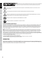
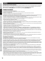
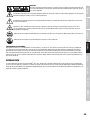
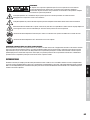
CAUTION:
To reduce the risk of electric shock, do not remove cover (or back). There are no user serviceable parts
inside. Maintenance and repairs should be exclusively carried out by qualified service personnel.
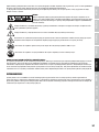
The warning triangle with lightning symbol indicates dangerous uninsulated voltage inside the unit, which may cause an
electrical shock.
The warning triangle with exclamation mark indicates important operating and maintenance instructions.
Warning! This symbol indicates a hot surface. Certain parts of the housing can become hot during operation. After use, wait for a
cool-down period of at least 10 minutes before handling or transporting the device.
Warning! This device is designed for use below 2000 metres in altitude.
Warning! This product is not intended for use in tropical climates.
CAUTION! HIGH VOLUMES IN AUDIO PRODUCTS!
This device is meant for professional use. Therefore, commercial use of this equipment is subject to the respectively applicable national accident
prevention rules and regulations. As a manufacturer, Adam Hall is obligated to notify you formally about the existence of potential health risks.
Hearing damage due to high volume and prolonged exposure: When in use, this product is capable of producing high sound-pressure levels (SPL)
that can lead to irreversible hearing damage in performers, employees, and audience members. For this reason, avoid prolonged exposure to
volumes in excess of 90 dB.
NOTE: This equipment has been tested and found to comply with the limits for a Class B digital device, pursuant to Part 15 of the FCC
Rules. These limits are designed to provide reasonable protection against harmful interference in a residential installation. This equipment
generates, uses and can radiate radio frequency energy and, if not installed and used in accordance with the instructions, may cause
harmful interference to radio communications. However, there is no guarantee that interference will not occur in a particular installation. If
this equipment does cause harmful interference to radio or television reception, which can be determined by turning the equipment off and
on, the user is encouraged to try to correct the interference by one or more of the following measures:
- Reorient or relocate the receiving antenna.
- Increase the separation between the equipment and receiver.
- Connect the equipment into an outlet on a circuit different from that to which the receiver is connected.
- Consult the dealer or an experienced radio/TV technician for help.
INTRODUCTION
Greatly facilitating your gigging life, the next generation of our MAUI
®
all-in-one column systems now comes with Class D amplification for increa-
sed power, punch and lighter weight. The line array design, BEM-optimized waveguides and LD Systems’ innovative DynX
®
DSP technology result in
distortion-free high definition sound with uniform dispersion and maximum coverage.

5
DEUTSCHENGLISH FRANCAIS
ESPAÑOL
POLSKI ITALIANO
简体中文
繁體中文
GENERAL INSTRUCTIONS
Before startup, the subwoofer of the LD Systems MAUI11G2 array system must be placed
upright on its feet, on a flat surface. Never operate your system on a trolley, as there is a risk
that the entire system might be unstable. Accidents and damage may result. To ensure ade-
quate cooling, during operation a minimum distance of 50 cm must be maintained between
the back of the subwoofer and other objects such as walls for example.
Please ensure the correct connection of audio and power for the system and all connected
devices such as mixers, CD players, etc. Use only undamaged cables of suitable diameter
and always unwind cable reels completely. If necessary, use cable bridges to avoid tripping
over loose cables. Never place the device directly on an edge. Do not place the subwoofer
on a table. To avoid unwanted background noise when turning on connected devices, always
turn on the system last and turn it off first.
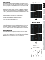
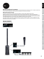
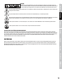
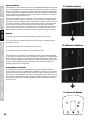
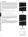
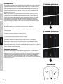
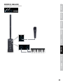
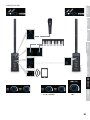
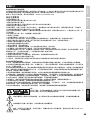
SETUP
The LD Systems MAUI11G2 array system consists of three components:
A. Subwoofer with integrated electronics for all system components.
B. Spacer column with connectors on bottom and top.
C. Column element with the speakers and a connection on the bottom.
After setting up the subwoofer at the desired location, the spacer column is plugged into
the subwoofer, and then the column element with 8 midrange drivers and the tweeters onto
the spacer column (please pay attention to the symbols on subwoofer, spacer column and
speaker columns, see drawing). Steel guiding pins facilitate the correct installation and
ensure at the same time a secure hold. Using the optional accessories, it is possible to have
two variants of wall mounting and two variants of mounting on stands.
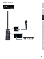
CONNECTION AND OPERATION
The device allows both the volume of the entire system and the volume of the subwoofer
in relation to the total volume to be adjusted separately. Source devices can be connected
using both balanced and unbalanced cables (XLR / 6.3 mm jack / RCA / mini jack). The
integrated 4-channel mixer offers a microphone input, a high-impedance instrument input
for an electric guitar for example, an input for source devices with line level and furthermore
a Bluetooth unit, which can be used in parallel to the 3.5 mm mini-jack input.
C. Speaker column
B. Spacer column
A. Subwoofer

6
DEUTSCH
ENGLISH
FRANCAISESPAÑOLPOLSKI
ITALIANO
简体中文繁體中文
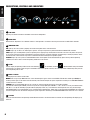
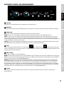
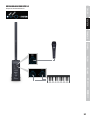
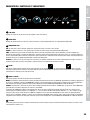
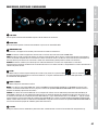
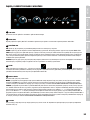
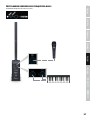
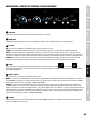
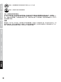
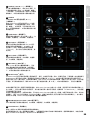
CONNECTIONS, CONTROLS AND INDICATORS
1 2
3 4 5 6
1
SUB LEVEL
Adjusting the volume ratio of the subwoofer to the column loudspeaker.
2
MAIN LEVEL
Overall volume adjustment. The subwoofer volume is also adjusted in accordance with the preset level on the SUB LEVEL controller.
3
INDICATOR LEDS
ON: Lights up once the system is properly connected to the power mains and switched on.
SIGNAL: Lights up as soon as an audio signal is present. The signal acquisition is performed before the MAIN LEVEL controller.
LIMIT: Lights up if the loudspeaker system is operating in the clipping range. A short flash of the LED is not critical. To protect the system,
an excessive signal level is gently turned down by the built-in limiter. If the limiter LED lights up permanently or for longer periods, reduce
the volume level. Failure to do so may result in a distorted sound and damage to the speaker system.
PROTECT: Lights up if the system is overloaded/overheated. The amplifiers are muted automatically. Upon reaching normal operating
conditions, the device reverts to normal operating mode after a few minutes.
4
SETUP
LEDs to display the operating mode: wall or stand mounting
, or subwoofer mounting . Optimised DSP settings are loaded
automatically in accordance with the type of installation used for the speaker columns; the same adjustment automatically takes place on
the corresponding LED as well.
5
MONO / STEREO
LED display for the mono or stereo mode.
MONO: When using a single MAUI11G2 unit, select the Mono preset (press switch N 6 SYSTEM, LED indicator should signal MONO). An
incoming stereo signal is now mono summed internally. You will find examples of system expansions and wiring in the CABLING EXAMPLES
section of this user’s manual.
STEREO: When using two MAUI11G2 units as a stereo set, select the Stereo preset (press switch N 6 SYSTEM,
LED indicator should signal STEREO), use the line inputs left and right (RCA jacks LINE IN R + L N 9, or XLR / 6.3 mm jack combo sockets
LINE IN R + L N 10) for controlling a playback device (CD player, mixer, etc.) and control the stereo expansion unit using the line output
SYSTEM OUT. When using a Bluetooth® unit as a playback device (Smartphone, Tablet), also use the line output SYSTEM OUT for controlling
the stereo expansion unit. You will find examples of system expansions and wiring in the CABLING EXAMPLES section of this user’s manual.
6
SYSTEM
Switch to alternate between the operating modes Mono and Stereo. If the desired mode is activated, the corresponding LED display (N 5)
will be lit.

7
DEUTSCHENGLISH FRANCAIS
ESPAÑOL
POLSKI ITALIANO
简体中文
繁體中文
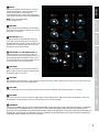
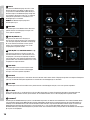
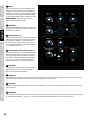
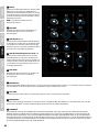
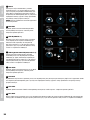
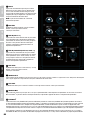
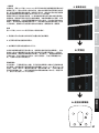
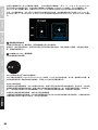
7
MIC IN
Balanced microphone input with XLR / 6.3 mm jack
combo socket (Mono). It is also possible to use an
unbalanced microphone cable (mono jack).
The microphone input has a built-in low-cut filter (Low-
cut) to suppress low-frequency noise and avoid feedback.
NOTE: There is no phantom power
on the microphone input.
8
MIC LEVEL
Volume controller for the microphone channel. When
turned to the left, the volume is lowered, when turned
to the right, it is increased.
9
LINE IN (RCA R + L)
Unbalanced stereo line input with RCA sockets for
connecting an external audio source (e.g. CD player,
keyboard). Both line inputs N 9 and N 10 can be used
simultaneously; the volume ratio must be set on the
instrument, or on the external player.
10
LINE IN (XLR / 6.3 mm combo jack R + L)
Balanced stereo line input with XLR / 6.3 mm jack
combo sockets for connecting a playback device (e.g.
mixer, keyboard). Both line inputs N 9 and N 10 can
be used simultaneously; the volume ratio must be set
on the instrument, or on the external player.
11
LINE LEVEL
Volume control for the line channel (N 9 and N 10).
When turned to the left, the volume is lowered, when
turned to the right, it is increased.
12
HI-Z INPUT
High-impedance mono input with 6.3 mm jack socket for acoustic or electric guitar. The HI-Z input has a built-in low-cut filter (Low-cut) to
suppress low-frequency noise and avoid feedback.
13
HI-Z LEVEL
Volume control for the HI-Z channel. When turned to the left, the volume is lowered, when turned to the right, it is increased.
14
MP3 INPUT
Stereo line input with 3.5 mm jack socket for an MP3 player or other playback device. Both interfaces MP3 and Bluetooth
®
can be used
simultaneously; the volume ratio must be set on the instrument, or on the external player.
15
BLUETOOTH
®
The mixer of the LDMAUI11G2 array system is equipped with Bluetooth, meaning that audio files from another Bluetooth device (e.g. Smartphone)
can be played back on the LDMAUI11G2 array system (maximum distance between both devices about 10 metres). If no Bluetooth device is
connected to the internal Bluetooth unit, the blue Bluetooth LED does not light up; the LED flashes at a frequency of about 3 Hz during pairing; if the
Bluetooth LED is on permanently, then a Bluetooth connection is established and the track playback can be started. The volume is adjusted using
the Bluetooth
®
volume controller (N 16) or on the source device.
8
7 9
11
10
13
12
14
16
17
15

8
DEUTSCH
ENGLISH
FRANCAISESPAÑOLPOLSKI
ITALIANO
简体中文繁體中文
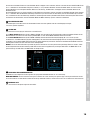
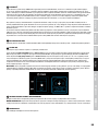
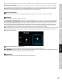
To pair and connect the internal Bluetooth device with a Bluetooth-enabled device, press and hold the HOLD TO LINK button for approx. 3
seconds until the Bluetooth LED flashes (approx. 3 Hz), enable Bluetooth on your Bluetooth device and search for available devices on the
user interface. Select “LD MAUI11G2” and pair your Bluetooth device with the internal Bluetooth device.
The playback can now start. To end the connection, press and hold the HOLD TO LINK button again for approx. 3 seconds. If the Bluetooth
connection is interrupted (e.g. the range is exceed), the Bluetooth LED goes out. Within approximately 90 seconds, the connection will
automatically be restored (Bluetooth device back within range). When 90 seconds is exceeded, the Bluetooth module of the LD MAUI11G2
array system will automatically be disabled.
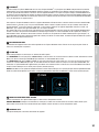
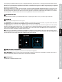
16
MP3/BLUETOOTH LEVEL
Volume controller for the MP3 channel and the Bluetooth unit. When turned to the left, the volume is lowered, when turned to the right,
it is increased.
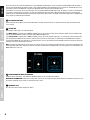
17
SYSTEM OUT
Balanced line output with 3-pin male XLR socket.
If the Mono mode is activated (point 5 MONO / STEREO), the sum of all input channels will be rendered in Mono. Select the Mono mode
and use the SYSTEM OUT line output to control another MAUI11G2 Mono unit.
If the Stereo mode is enabled (point 5 MONO / STEREO), the left channel of all stereo inputs (N 9, 10, 14 and 15) is processed internally
and rendered by the MAUI11G2 array system, while the right channel of all stereo inputs is rendered by the SYSTEM OUT line output to
control another MAUI11G2 unit externally as a stereo expansion. The sum of the Mono channels MIC IN and HI-Z IN is output in equal parts
internally on the left and externally on the right.
Note: To achieve the same volume as well as the same sound as the main unit with the stereo expansion, turn the volume controller of the
stereo expansion LINE LEVEL clockwise (maximum) and place the SUB LEVEL and MAIN LEVEL in the same position as the SUB LEVEL and
MAIN LEVEL of the main unit.
19
18
18
POWER CONNECTOR WITH FUSE HOLDER
IEC power socket with built-in fuse holder. An appropriate power cord is included in the delivery.
IMPORTANT INFORMATION: Replace the fuse only with a fuse of the same type and rating. Please observe the label on the housing. If the
fuse blows repeatedly, please contact an authorised service centre.
19
POWER ON / OFF
On / Off switch for the power supply of the device.

9
DEUTSCHENGLISH FRANCAIS
ESPAÑOL
POLSKI ITALIANO
简体中文
繁體中文
WHAT DOES LD SYSTEMS DynX
®
DSP STAND FOR?
DSP stands for Digital Signal Processing, DynX
®
comprises the Limiter, EQ, Compressor and Crossover features. The digital signal processing
ensures maximum audio performance with maximum clarity and protects the PA system from overload.
WHAT EXACTLY DOES DynX
®
DSP DO?
The Limiter function protects the speakers and prevents distortions caused by overload. Separate limiters for bass
midrange and high range attenuate the signal when the level exceeds a value which could have a negative effect. Each limiter is
optimised for one of the three seamlessly contiguous frequency ranges (multi-band limiter). The system can be operated in this manner
with a higher overall sound pressure as extreme peaks are automatically lowered, so that the total volume does not need to be reduced.
The Multiband EQ works over the entire frequency range and optimises the overall sound of the system.
The crossovers divide the audio signal according to the frequency range of the respective speakers, namely the subwoofer or the mids
and tweeters of the array column. The amplitude and running-time optimisation of the crossover ensures that all frequencies are output
evenly and reach the listener at the same time.
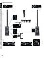
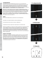
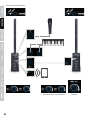
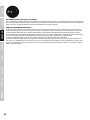
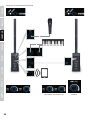
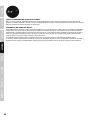
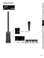
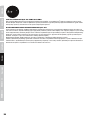
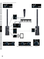
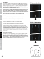
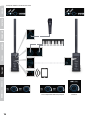
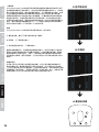
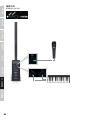
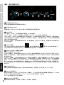
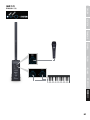
CABLING EXAMPLES
Example of Mono operating mode.

10
DEUTSCH
ENGLISH
FRANCAISESPAÑOLPOLSKI
ITALIANO
简体中文繁體中文
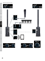
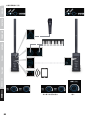
Example of Stereo operating mode.
Same settings as on the main unit Maximum

11
DEUTSCHENGLISH FRANCAIS
ESPAÑOL
POLSKI ITALIANO
简体中文
繁體中文
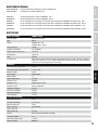
OPTIONAL ACCESSORIES
LDM11G2SATBAG: Carrying bag for LDMAUI11G2 speaker column
LDM11G2SUBPC: Protective cover for LDMAUI11G2 subwoofer
LDMG2SPS: Stand for LDMAUIG2 speaker column, black
LDMG2SPSW: Stand for LDMAUIG2 speaker column, white
LDMG2IK1: Installation Set for wall mounting the LDMAUIG2 speaker column (flat mounting) - black
LDMG2IK1W: Installation Set for wall mounting the LDMAUIG2 speaker column (flat mounting) - white
LDMG2IK2: Installation Set for wall mounting the LDMAUIG2 speaker column (adjustable angle) - black
LDMG2IK2W: Installation Set for wall mounting the LDMAUIG2 speaker column (adjustable angle) - white
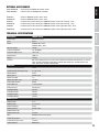
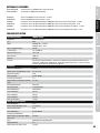
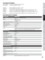
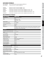
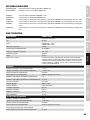
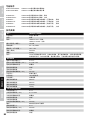
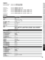
TECHNICAL SPECIFICATIONS
Model Name: LDMAUI11G2(W)
Product Type: Column PA system
Type: Active
Colour: LDMAUI11G2 - black
LDMAUI11G2W - white
Max. SPL (peak): 124 dB
Frequency Response: 50 - 20,000 Hz
Dispersion Angle (H x V): 120° x 20°
Overall Height: 2030 mm
Weight: 24.9 kg
Features: DSP-based signal processing, xcellent sound dispersion, bluetooth audio streaming, 4-channel
mixer on board, mono/stereo application, automatic DSP adjustment, available in black and
white, wall mount and floor stand available
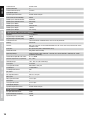
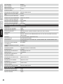
subwoofer
Low/mid Driver Dimensions: 3x 6.5“
Low/mid Driver Dimensions (mm): 3 x 165.1 mm
Woofer Magnet: Ferrite
Woofer Brand: Custom made
Woofer Voice Coil: 1.5"
Woofer Voice Coil (mm): 38.1 mm
Cabinet Construction: Vented
Cabinet Material: 15 mm plywood
Cabinet Surface: Texture paint
Subwoofer Width: 285 mm
Subwoofer Height: 650 mm
Subwoofer Depth: 373 mm
Subwoofer Weight: 16.9 kg
Mid/Hi System
Midrange Size: 8 x 3"
Midrange Size: 8 x 76.2 mm
Midrange Magnet: Ferrite
Midrange Brand: Custom made
Midrange Voice Coil: 1"
Midrange Voice Coil: 25.4 mm
Horn: BEM optimized CD wave guide
Tweeter Dimensions: 2 x 1"
Tweeter Dimensions (mm): 25.4 mm
Tweeter Magnet: Neodymium

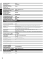
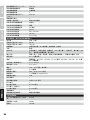
12
DEUTSCH
ENGLISH
FRANCAISESPAÑOLPOLSKI
ITALIANO
简体中文繁體中文
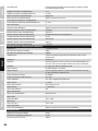
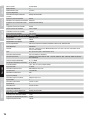
Tweeter Brand: Custom made
Tweeter Voice Coil: 1"
Tweeter Voice Coil (mm): 25.4 mm
Loudspeaker Inputs: 1
Speaker Input Connections: Custom-made multi-pin
Cabinet Construction Mid/High: Closed
Mid/Hi System Cabinet Material: Aluminium
Mid/Hi System Cabinet Surface: HD coating
Mid/Hi System Width: 96 mm
Mid/Hi System Height: 620/ 730 mm
Mid/Hi System Depth: 104 mm
Mid/Hi System Weight: 5.4 / 2.6 kg
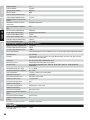
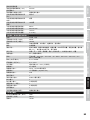
Amplifier Module (integrated in Subwoofer)
Amplifier: 3-way Class D
Amplifier Output System (RMS): 500 W
Amplifier Output System (Peak): 1000 W
Protection Circuits: Thermal overload, multiband limiter, short circuit, DC protection
Cooling: Convection
Controls: Mic Level, sub level, line level, MP3/Bluetooth level, Hi-Z level, main level, mono/stereo switch,
bluetooth button
Indicators: On, signal, limit, protect, mono/stereo, setup
Power Connector: IEC (power cable included)
Operating Voltage: Switching power supply, 100 V AC - 120 V AC, 50 - 60 Hz, 200 V AC - 240 V AC, 50 - 60 Hz
(automatic conversion)
Power Consumption Off / On / Max.: 0 / 11 / 600 W
Ambient Temperature (in operation): 0°C - 40°C
Humidity Range: 10% - 80% rel. (non condensing)
Line Inputs: 2 x stereo
Line Input Connectors: RCA, XLR/6.3 mm jack
Line Outputs: 1x System Out
Line Output Connectors: XLR
Mic Inputs: 1
Mic Input Connectors: XLR / 6.3 mm jack
MP3 Inputs: 1
MP3 Input Connectors: 3.5 mm jack
HI-Z Inputs: 1
Hi-Z Input Connectors: 6.3 mm jack
Loudspeaker Outputs: 1
Speaker Output Connections: Custom-made multi-pin
DSP Characteristics
Bit depth AD/DA Converter: 24 bit
Internal Sampling Frequency: 48 kHz
Signal/noise ratio: 100 dB

13
DEUTSCHENGLISH FRANCAIS
ESPAÑOL
POLSKI ITALIANO
简体中文
繁體中文
MANUFACTURER´S DECLARATIONS
MANUFACTURER‘S WARRANTY & LIMITATIONS OF LIABILITY
You can find our current warranty conditions and limitations of liability at: http://www.adamhall.com/media/shop/downloads/documents/
manufacturersdeclarations.pdf. To request warranty service for a product, please contact Adam Hall GmbH, Daimler Straße 9, 61267 Neu
Anspach / Email: [email protected] / +49 (0)6081 / 9419-0.
CORRECT DISPOSAL OF THIS PRODUCT
(valid in the European Union and other European countries with a differentiated waste collection system)
This symbol on the product, or on its documents indicates that the device may not be treated as household waste. This is to avoid
environmental damage or personal injury due to uncontrolled waste disposal. Please dispose of this product separately from other waste
and have it recycled to promote sustainable economic activity. Household users should contact either the retailer where they purchased
this product, or their local government office, for details on where and how they can recycle this item in an environmentally friendly manner.
Business users should contact their supplier and check the terms and conditions of the purchase contract. This product should not be mixed
with other commercial waste for disposal.
FCC STATEMENT
This device complies with Part 15 of the FCC Rules. Operation is subject to the following two conditions:
(1) This device may not cause harmful interference, and
(2) This device must accept any interference received, including interference that may cause undesired operation
CE Compliance
Adam Hall GmbH states that this product meets the following guidelines (where applicable):
R&TTE (1999/5/EC) or RED (2014/53/EU) from June 2017
Low voltage directive (2014/35/EU)
EMV directive (2014/30/EU)
RoHS (2011/65/EU)
The complete declaration of conformity can be found at www.adamhall.com.
Furthermore, you may also direct your enquiry to [email protected].

14
DEUTSCH
ENGLISH
FRANCAISESPAÑOLPOLSKI
ITALIANO
简体中文繁體中文
DEUTSCH
SIE HABEN DIE RICHTIGE WAHL GETROFFEN!
Dieses Gerät wurde unter hohen Qualitätsanforderungen entwickelt und gefertigt, um viele Jahre einen reibungslosen Betrieb zu gewährleisten.
Dafür steht LD Systems mit seinem Namen und der langjährigen Erfahrung als Hersteller hochwertiger Audioprodukte. Bitte lesen Sie diese
Bedienungsanleitung sorgfältig, damit Sie Ihr neues Produkt von LD Systems schnell optimal einsetzen können.
Mehr Informationen zu LD SYSTEMS finden Sie auf unserer Internetseite WWW.LD-SYSTEMS.COM
SICHERHEITSHINWEISE
1. Lesen Sie diese Anleitung bitte sorgfältig durch.
2. Bewahren Sie alle Informationen und Anleitungen an einem sicheren Ort auf.
3. Befolgen Sie die Anweisungen.
4. Beachten Sie alle Warnhinweise. Entfernen Sie keine Sicherheitshinweise oder andere Informationen vom Gerät.
5. Verwenden Sie das Gerät nur in der vorgesehenen Art und Weise.
6. Verwenden Sie ausschließlich stabile und passende Stative bzw. Befestigungen (bei Festinstallationen). Stellen Sie sicher, dass Wandhalterungen
ordnungsgemäß installiert und gesichert sind. Stellen Sie sicher, dass das Gerät sicher installiert ist und nicht herunterfallen kann.
7. Beachten Sie bei der Installation die für Ihr Land geltenden Sicherheitsvorschriften.
8. Installieren und betreiben Sie das Gerät nicht in der Nähe von Heizkörpern, Wärmespeichern, Öfen oder sonstigen Wärmequellen. Sorgen
Sie dafür, dass das Gerät immer so installiert ist, dass es ausreichend gekühlt wird und nicht überhitzen kann.
9. Platzieren Sie keine Zündquellen wie z.B. brennende Kerzen auf dem Gerät.
10. Lüftungsschlitze dürfen nicht blockiert werden.
11. Halten Sie einen Mindestabstand von 20 cm seitlich und oberhalb des Geräts ein.
12. Betreiben Sie das Gerät nicht in unmittelbarer Nähe von Wasser. Bringen Sie das Gerät nicht mit brennbaren Materialien, Flüssigkeiten
oder Gasen in Berührung. Direkte Sonneneinstrahlung vermeiden!
13. Sorgen Sie dafür, dass kein Tropf- oder Spritzwasser in das Gerät eindringen kann. Stellen Sie keine mit Flüssigkeit gefüllten Behältnisse
wie Vasen oder Trinkgefäße auf das Gerät.
14. Sorgen Sie dafür, dass keine Gegenstände in das Gerät fallen können.
15. Betreiben Sie das Gerät nur mit dem vom Hersteller empfohlenen und vorgesehenen Zubehör.
16. Öffnen Sie das Gerät nicht und verändern Sie es nicht.
17. Überprüfen Sie nach dem Anschluss des Geräts alle Kabelwege, um Schäden oder Unfälle, z. B. durch Stolperfallen zu vermeiden.
18. Achten Sie beim Transport darauf, dass das Gerät nicht herunterfallen und dabei möglicherweise Sach- und Personenschäden verursachen kann.
19. Wenn Ihr Gerät nicht mehr ordnungsgemäß funktioniert, Flüssigkeiten oder Gegenstände in das Geräteinnere gelangt sind, oder das
Gerät anderweitig beschädigt wurde, schalten Sie es sofort aus und trennen es von der Netzsteckdose (sofern es sich um ein aktives Gerät
handelt). Dieses Gerät darf nur von autorisiertem Fachpersonal repariert werden.
20. Verwenden Sie zur Reinigung des Geräts ein trockenes Tuch.
21. Beachten Sie alle in Ihrem Land geltenden Entsorgungsgesetze. Trennen Sie bei der Entsorgung der Verpackung bitte Kunststoff und
Papier bzw. Kartonagen voneinander.
22. Kunststoffbeutel müssen außer Reichweite von Kindern aufbewahrt werden.
23. Sämtliche vom Benutzer vorgenommenen Änderungen und Modifikationen, denen die für die Einhaltung der Richtlinien verantwortliche
Partei nicht ausdrücklich zugestimmt hat, können zum Entzug der Betriebserlaubnis für das Gerät führen.
BEI GERÄTEN MIT NETZANSCHLUSS
24. ACHTUNG: Wenn das Netzkabel des Geräts mit einem Schutzkontakt ausgestattet ist, muss es an einer Steckdose mit Schutzleiter
angeschlossen werden. Deaktivieren Sie niemals den Schutzleiter eines Netzkabels.
25. Schalten Sie das Gerät nicht sofort ein, wenn es starken Temperaturschwankungen ausgesetzt war (beispielsweise nach dem Transport).
Feuchtigkeit und Kondensat könnten das Gerät beschädigen. Schalten Sie das Gerät erst ein, wenn es Zimmertemperatur erreicht hat.
26. Bevor Sie das Gerät an die Steckdose anschließen, prüfen Sie zuerst, ob die Spannung und die Frequenz des Stromnetzes mit den auf
dem Gerät angegebenen Werten übereinstimmen. Verfügt das Gerät über einen Spannungswahlschalter, schließen Sie das Gerät nur an die
Steckdose an, wenn die Gerätewerte mit den Werten des Stromnetzes übereinstimmen. Wenn das mitgelieferte Netzkabel bzw. der mitgelie-
ferte Netzadapter nicht in Ihre Netzsteckdose passt, wenden Sie sich an Ihren Elektriker.
27. Treten Sie nicht auf das Netzkabel. Sorgen Sie dafür, dass spannungsführende Kabel speziell an der Netzbuchse bzw. am Netzadapter
und der Gerätebuchse nicht geknickt werden.
28. Achten Sie bei der Verkabelung des Geräts immer darauf, dass das Netzkabel bzw. der Netzadapter stets frei zugänglich ist. Trennen Sie
das Gerät stets von der Stromzuführung, wenn das Gerät nicht benutzt wird, oder Sie das Gerät reinigen möchten. Ziehen Sie Netzkabel und
Netzadapter immer am Stecker bzw. am Adapter und nicht am Kabel aus der Steckdose. Berühren Sie Netzkabel und Netzadapter niemals mit
nassen Händen.
29. Schalten Sie das Gerät möglichst nicht schnell hintereinander ein und aus, da sonst die Lebensdauer des Geräts beeinträchtigt werden könnte.
30. WICHTIGER HINWEIS: Ersetzen Sie Sicherungen ausschließlich durch Sicherungen des gleichen Typs und Wertes. Sollte eine Sicherung
wiederholt auslösen, wenden Sie sich bitte an ein autorisiertes Servicezentrum.
31. Um das Gerät vollständig vom Stromnetz zu trennen, entfernen Sie das Netzkabel bzw. den Netzadapter aus der Steckdose.
32. Wenn Ihr Gerät mit einem verriegelbaren Netzanschluss bestückt ist, muss der passende Gerätestecker entsperrt werden, bevor er entfernt
werden kann. Das bedeutet aber auch, dass das Gerät durch ein Ziehen am Netzkabel verrutschen und herunterfallen kann, wodurch Personen
verletzt werden und/oder andere Schäden auftreten können. Verlegen Sie Ihre Kabel daher immer sorgfältig.
33. Entfernen Sie Netzkabel und Netzadapter aus der Steckdose bei Gefahr eines Blitzschlags oder wenn Sie das Gerät länger nicht verwenden.

15
DEUTSCHENGLISH FRANCAIS
ESPAÑOL
POLSKI ITALIANO
简体中文
繁體中文
ACHTUNG
Entfernen Sie niemals die Abdeckung, da sonst das Risiko eines elektrischen Schlages besteht. Im
Inneren des Geräts befinden sich keine Teile, die vom Bediener repariert oder gewartet werden können.
Lassen Sie Wartung und Reparaturen ausschließlich von qualifiziertem Servicepersonal durchführen.
Das gleichseitige Dreieck mit Blitzsymbol warnt vor nichtisolierten, gefährlichen Spannungen im Geräteinneren, die einen elektrischen
Schlag verursachen können.
Das gleichseitige Dreieck mit Ausrufungszeichen kennzeichnet wichtige Bedienungs- und Wartungshinweise.
Warnung! Dieses Symbol kennzeichnet heiße Oberflächen. Während des Betriebs können bestimmte Teile des Gehäuses heiß werden.
Berühren oder transportieren Sie das Gerät nach einem Einsatz erst nach einer Abkühlzeit von mindestens 10 Minuten.
Warnung! Dieses Gerät ist für eine Nutzung bis zu einer Höhe von maximal 2000 Metern über dem Meeresspiegel bestimmt.
Warnung! Dieses Gerät ist nicht für den Einsatz in tropischen Klimazonen bestimmt.
ACHTUNG HOHE LAUTSTÄRKEN BEI AUDIOPRODUKTEN!
Dieses Gerät ist für den professionellen Einsatz vorgesehen. Der kommerzielle Betrieb dieses Geräts unterliegt den jeweils gültigen nationalen
Vorschriften und Richtlinien zur Unfallverhütung. Als Hersteller ist Adam Hall gesetzlich verpflichtet, Sie ausdrücklich auf mögliche Gesundheitsrisik-
en hinzuweisen. Gehörschäden durch hohe Lautstärken und Dauerbelastung: Bei der Verwendung dieses Produkts können hohe Schalldruckpegel
(SPL) erzeugt werden, die bei Künstlern, Mitarbeitern und Zuschauern zu irreparablen Gehörschäden führen können. Vermeiden Sie länger
anhaltende Belastung durch hohe Lautstärken über 90 dB.
EINFÜHRUNG
Mit der neuesten Generation unseres MAUI
®
-Säulensystems wird Ihr Bandleben deutlich einfacher: Unsere PA-Komplettlösung kommt jetzt mit
Class-D-Verstärkung und bietet damit eine höhere Leistung, einen satteren Punch und ein geringeres Gewicht. Dank Line-Array-Konfiguration,
BEM-optimierten Waveguides und LD Systems’ innovativer DynX
®
-DSP-Technologie liefert sie einen verzerrungsfreien High-Definition-Klang mit
gleichmäßiger Verteilung und maximaler Reichweite.

16
DEUTSCH
ENGLISH
FRANCAISESPAÑOLPOLSKI
ITALIANO
简体中文繁體中文
ALLGEMEINE HINWEISE
Der Subwoofer des LD Systems MAUI11G2 Array-Systems muss vor der Inbetriebnahme
senkrecht auf ebener Fläche auf seine Füße gestellt werden. Betreiben Sie das System niemals
auf einem Rollwagen, da die Gefahr besteht, dass sich das gesamte System unkontrolliert in
Bewegung setzt. Unfälle und Beschädigungen können die Folge sein. Um eine ausreichende
Kühlung zu gewährleisten, muss bei Betrieb zwischen der Rückseite des Subwoofers und anderen
Objekten wie Wänden o. ä. ein Mindestabstand von 50 cm eingehalten werden.
Bitte achten Sie bei dem System sowie den angeschlossenen Geräten wie Mischpulten,
CD-Playern etc. auf den korrekten Anschluss von Audio- und Stromverbindungen. Verwenden
Sie ausschließlich unbeschädigte Kabel mit geeignetem Durchmesser und rollen Sie Kabel-
rollen immer vollständig ab. Verwenden Sie gegebenenfalls Kabelbrücken, um Stolperfallen
durch lose Kabel zu vermeiden. Stellen Sie das Gerät niemals direkt an einer Kante auf.
Positionieren Sie den Subwoofer nicht auf einem Tisch. Um ungewollte Nebengeräusche
beim Einschalten angeschlossener Geräte zu vermeiden, schalten Sie das System immer als
letztes Gerät ein und als erstes Gerät aus.
AUFBAU
Das LD Systems MAUI11G2 Array-System besteht aus drei Komponenten:
A. Subwoofer mit integrierter Elektronik für alle Systemkomponenten.
B. Eine Distanzsäule mit Anschlüssen auf Unter- und Oberseite.
C. Säulenelement mit den Lautsprechern und dem Anschluss auf der Unterseite.
Nachdem der Subwoofer an der gewünschten Stelle aufgestellt wurde, wird die Distanzsäule
auf den Subwoofer aufgesteckt und danach das Säulenelement mit den 8 Mittentönern
und den Hochtönern auf die Distanzsäule (Bitte Symbole auf Subwoofer, Distanzsäule und
Lautsprechersäule beachten, siehe Zeichnung). Führungsbolzen aus Stahl erleichtern die
korrekte Montage und gewährleisten gleichzeitig sicheren Halt. Mit Hilfe von optionalem
Zubehör besteht die Möglichkeit der Wandmontage in zwei Varianten und der Stativmontage
ebenso in zwei Varianten.
ANSCHLUSS UND BETRIEB
Am Gerät lässt sich sowohl die Lautstärke des gesamten Systems als auch die Lautstärke
des Subwoofers im Verhältnis zur Gesamtlautstärke einstellen. Zuspielgeräte lassen sich
sowohl über symmetrische als auch unsymmetrische Kabel (XLR / 6,3 mm Klinke / Cinch /
Mini-Klinke) anschließen. Das integrierte 4-Kanal Mischpult bietet einen Mikrofoneingang,
einen hochohmigen Instrumenteneingang für z.B. eine Akustik-Gitarre, einen Eingang für
Zuspielgeräte mit Line-Pegel und darüber hinaus eine Bluetooth-Einheit, die parallel zum
3,5mm Klinkeneingang genutzt werden kann.
C. Lautsprechersäule
B. Distanzsäule
A. Subwoofer

17
DEUTSCHENGLISH FRANCAIS
ESPAÑOL
POLSKI ITALIANO
简体中文
繁體中文
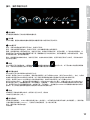
ANSCHLÜSSE, BEDIEN- UND ANZEIGEELEMENTE
1 2
3 4 5 6
1
SUB LEVEL
Einstellung des Lautstärkeverhältnisses des Subwoofers zum Säulenlautsprecher.
2
MAIN LEVEL
Einstellung der Gesamtlautstärke. Die Subwooferlautstärke wird entsprechend der Voreinstellung am SUB LEVEL Pegelsteller mitgeregelt.
3
ANZEIGE LEDS
ON: Leuchtet, wenn das Gerät korrekt am Stromnetz angeschlossen und eingeschaltet ist.
SIGNAL: Leuchtet auf, wenn am Gerät ein Audiosignal anliegt. Die Signalerfassung erfolgt vor dem MAIN LEVEL-Regler.
LIMIT: Leuchtet auf, wenn das Lautsprecher-System im oberen Grenzbereich betrieben wird. Ein kurzes Aufleuchten der LED ist dabei
unkritisch. Um das System zu schützen, wird ein überhöhter Signal-Pegel vom integrierten Limiter sanft heruntergeregelt. Leuchtet die
Limiter-LED länger oder dauerhaft, reduzieren Sie den Lautstärkepegel. Eine Nichtbeachtung kann zu einer verzerrten Klangwiedergabe und
zur Beschädigung des Lautsprechersystems führen.
PROTECT: Leuchtet auf, falls das System überlastet/überhitzt. Die Verstärker werden automatisch stummgeschaltet. Nach Erreichen normaler
Betriebsbedingungen wechselt das Gerät nach einigen Minuten wieder in den normalen Betriebsmodus.
4
SETUP
LEDs zum Anzeigen der Betriebsart Wand-, bzw. Stativmontage
, oder Subwoofermontage . Optimierte DSP-Einstellungen
werden für die Verwendung der Lautsprechersäule in der jeweiligen Montageart automatisch geladen, ebenso erfolgt die Umstellung auf die
entsprechende Anzeige-LED automatisch.
5
MONO / STEREO
Anzeige-LEDs für die Mono-, bzw. Stereo-Betriebsart.
MONO: Aktivieren Sie bei der Verwendung einer einzelnen MAUI11G2 Anlage das Mono-Preset (Taster Nr. 6 SYSTEM drücken, Anzeige-LED
MONO muss leuchten). Ein anliegendes Stereo-Signal wird nun intern Mono summiert. Beispiele für Systemerweiterungen und Verkabelung
finden Sie in dieser Anleitung unter VERKABELUNGSBEISPIELE.
STEREO: Aktivieren Sie bei der Verwendung zweier MAUI11G2 Anlagen als Stereo-Set das Stereo-Preset (Taster Nr. 6 SYSTEM drücken,
Anzeige-LED STEREO muss leuchten), nutzen für die Ansteuerung durch ein Zuspielgerät (CD-Player, Mischpult etc.) die Line-Eingänge
rechts und links (Cinch-Buchsen LINE IN R + L Nr. 9, oder XLR / 6,3 mm Klinke Combo-Buchsen LINE IN R + L Nr. 10) und steuern die
Stereo Erweiterungs-Einheit mit Hilfe des Line-Ausgangs SYSTEM OUT an. Bei der Verwendung einer Bluetooth®-Einheit als Zuspielgerät
(Smartphone, Tablet) nutzen Sie ebenfalls den Line-Ausgang SYSTEM OUT für die Ansteuerung der Stereo Erweiterungs-Einheit. Beispiele
für Systemerweiterungen und Verkabelung finden Sie in dieser Anleitung unter VERKABELUNGSBEISPIELE.
6
SYSTEM
Taster zum Umschalten der Betriebsarten Mono und Stereo. Ist die gewünschte Betriebsart aktiviert, leuchtet die entsprechende
Anzeige-LED (Nr. 5).

18
DEUTSCH
ENGLISH
FRANCAISESPAÑOLPOLSKI
ITALIANO
简体中文繁體中文
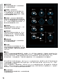
7
MIC IN
Symmetrischer Mikrofoneingang mit XLR / 6,3 mm
Klinken Combo-Buchse (Mono). Die Nutzung eines
unsymmetrischen Mikrofonkabels (Mono-Klinke) ist
ebenfalls möglich. Der Mikrofoneingang verfügt über
eine integrierte Tiefensperre (Low-cut), um störende
tieffrequente Signalanteile zu unterdrücken und
Rückkopplungen zu vermeiden.
HINWEIS: Am Mikrofoneingang liegt keine
Phantomspeisung an.
8
MIC LEVEL
Lautstärkeregler für den Mikrofon-Kanal. Nach links
gedreht wird der Lautstärkepegel verringert, nach
rechts gedreht angehoben.
9
LINE IN (CINCH R + L)
Unsymmetrischer Stereo-Line-Eingang mit
Cinch-Buchsen zum Anschließen eines Zuspielgeräts
(z.B. CD-Player, Keyboard). Die beiden Line-Eingänge
Nr. 9 und 10 können bei Bedarf simultan genutzt
werden, das Lautstärkenverhältnis muss an den
Zuspielgeräten eingestellt werden.
10
LINE IN (XLR / 6,3 mm Klinke Combo R + L)
Symmetrischer Stereo-Line-Eingang mit XLR / 6,3
mm Klinke Combo-Buchsen zum Anschließen eines
Zuspielgeräts (z.B. Mischpult, Keyboard). Die beiden
Line-Eingänge Nr. 9 und 10 können bei Bedarf simultan
genutzt werden, das Lautstärkenverhältnis muss an den
Zuspielgeräten eingestellt werden.
11
LINE LEVEL
Lautstärkeregler für den Line-Kanal (Nr. 9 und Nr.
10). Nach links gedreht wird der Lautstärkepegel
verringert, nach rechts gedreht angehoben.
12
HI-Z INPUT
Hochohmiger Mono-Eingang mit 6,3 mm Klinken-Buchse für Akustik- oder E-Gitarre. Der HI-Z Eingang verfügt über eine integrierte Tiefensperre
(Low-cut) um störende tieffrequente Signalanteile zu unterdrücken und Rückkopplungen zu vermeiden.
13
HI-Z LEVEL
Lautstärkeregler für den HI-Z-Kanal. Nach links gedreht wird der Lautstärkepegel verringert, nach rechts gedreht angehoben.
14
MP3 INPUT
Stereo-Line-Eingang mit 3,5 mm Klinken-Buchse für einen MP3-Player oder ein anderes Zuspielgerät. Die beiden Schnittstellen MP3 und
Bluetooth
®
können bei Bedarf simultan genutzt werden, das Lautstärkenverhältnis muss an den Zuspielgeräten eingestellt werden.
15
BLUETOOTH
®
Das Mischpult des LDMAUI11G2 Array-Systems ist mit Bluetooth ausgestattet, was bedeutet, dass Audio-Dateien eines anderen Bluetooth-Geräts
(z.B. Smartphone, Tablet) auf dem MAUI11G2 Array-System wiedergegeben werden können (maximale Entfernung zwischen beiden Geräten ca.
10 Meter). Ist kein Bluetooth-Gerät mit der internen Bluetooth-Einheit verbunden, zeigt die blaue Bluetooth-LED kein Signal an, während der
Kopplungsbereitschaft blinkt die LED rythmisch in einer Frequenz von ca. 3 Hz, leuchtet die Bluetooth-LED permanent, besteht eine
Bluetooth-Verbindung und die Titelwiedergabe kann gestartet werden. Die Lautstärkeneinstellung erfolgt mit Hilfe des Bluetooth® Lautstärkereglers
(Nr. 16), bzw. am Zuspielgerät.
8
7 9
11
10
13
12
14
16
17
15

19
DEUTSCHENGLISH FRANCAIS
ESPAÑOL
POLSKI ITALIANO
简体中文
繁體中文
Um die interne Bluetooth-Einheit mit einem Bluetooth-Gerät zu koppeln und zu verbinden, drücken und halten Sie den HOLD TO LINK-Taster
für ca. 3 Sekunden bis die Bluetooth-LED rythmisch blinkt (ca. 3 Hz), aktivieren Bluetooth auf Ihrem Bluetooth-Gerät und suchen auf der
Benutzeroberfläche nach verfügbaren Geräten. Wählen Sie den Eintrag „LD MAUI11G2“ und koppeln damit Ihr Bluetooth-Gerät mit der
Bluetooth-Einheit.
Die Titelwiedergabe kann nun gestartet werden. Um die Verbindung zu beenden, drücken und halten Sie den HOLD TO LINK-Taster abermals
für ca. 3 Sekunden. Wird die Bluetooth-Verbindung unterbrochen (z.B. überschreiten der Reichweite), erlischt die Bluetooth-LED. Innerhalb
von ca. 90 Sekunden kann die Verbindung automatisch wiederhergestellt werden (Bluetooth-Gerät wieder in Reichweite). Bei Überschreiten
der Zeitdauer von 90 Sekunden, wird das Bluetooth-Modul des MAUI11G2 Array-Systems automatisch deaktiviert.
16
MP3/BLUETOOTH LEVEL
Lautstärkeregler für den MP3-Kanal und die Bluetooth-Einheit. Nach links gedreht wird der Lautstärkepegel verringert,
nach rechts gedreht angehoben.
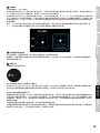
17
SYSTEM OUT
Symmetrischer Line-Ausgang mit männlicher 3-Pol XLR-Buchse.
Ist die Mono-Betriebsart aktiviert (Punkt 5 MONO / STEREO), wird die Summe aller Eingangskanäle in Mono ausgegeben. Wählen Sie die
Mono-Betriebsart und nutzen den Line-Ausgang SYSTEM OUT, um eine weitere MAUI11G2 Mono-Einheit anzusteuern.
Ist die Stereo-Betriebsart aktiviert (Punkt 5 MONO / STEREO), wird der linke Kanal aller Stereo-Eingänge (Nr. 9, 10, 14 und 15) intern
verarbeitet und vom MAUI11G2 Array System wiedergegeben, der rechte Kanal aller Stereo-Eingänge wird am Line-Ausgang SYSTEM OUT
ausgegeben, um eine weitere MAUI11G2 Einheit extern als Stereo-Erweiterung anzusteuern. Die Summe der Mono-Kanäle MIC IN und HI-Z IN
wird zu gleichen Teilen intern links und extern rechts wiedergegeben.
Hinweis: Um bei der Stereo-Erweiterung sowohl die gleiche Lautstärke als auch den gleichen Klang der Haupt-Einheit zu erzielen, stellen
Sie den Pegelsteller der Stereo-Erweiterung LINE LEVEL auf Rechtsanschlag (Maximum) und bringen SUB LEVEL und MAIN LEVEL in die
gleiche Stellung, wie SUB LEVEL und MAIN LEVEL der Haupt-Einheit.
18
NETZBUCHSE UND SICHERUNGSHALTER
IEC Netzbuchse mit integriertem Sicherungshalter. Ein geeignetes Netzkabel befindet sich im Lieferumfang.
WICHTIGER HINWEIS: Ersetzen Sie die Sicherung ausschließlich durch eine Sicherung des gleichen Typs und mit gleichen Werten. Achten
Sie auf den Aufdruck auf dem Gehäuse. Sollte die Sicherung wiederholt auslösen, wenden Sie sich bitte an ein autorisiertes Servicezentrum.
19
POWER ON / OFF
Ein- / Ausschalter für die Spannungszufuhr des Geräts.
19
18

20
DEUTSCH
ENGLISH
FRANCAISESPAÑOLPOLSKI
ITALIANO
简体中文繁體中文
WAS BEDEUTET LD SYSTEMS DynX
®
DSP?
DSP ist die Abkürzung für Digital Signal Processing (Digitale Signalverarbeitung), DynX® beinhaltet die Funktionen Limiter, EQ, Kompressor
und Frequenzweiche. Die digitale Signalverarbeitung gewährleistet eine optimale Audiowiedergabe mit maximaler Klarheit und schützt
gleichzeitig das PA-System vor Überlastung.
WAS GENAU BEWIRKT DynX
®
DSP?
Die Limiter-Funktion schützt die Lautsprecher und verhindert durch Übersteuerung verursachte Verzerrungen. Separate Limiter für den
Bass-Mitten- und Höhenbereich schwächen das Signal ab, sobald der Pegel einen Wert übersteigt, der sich negativ auswirken könnte. Jeder
Limiter ist für einen der drei nahtlos aneinander anschließenden Frequenzbereiche optimiert (Multiband-Limiter). Das System lasst sich auf
diese Weise mit einem insgesamt höheren Schalldruck betreiben, da extreme Signalspitzen automatisch abgeschwächt werden, sodass die
Gesamtlautstärke nicht reduziert werden muss.
Der Multiband-EQ bearbeitet den gesamten Frequenzbereich und optimiert den Gesamtklang des Systems.
Die Frequenzweichen teilen das Audiosignal je nach Frequenzbereich den jeweiligen Lautsprechern, also dem Subwoofer bzw. den Mitten- und
Hochtönern der Array-Säule zu. Die Amplituden- und Laufzeit-Optimierung der Frequenzweichen sorgt dafür, dass alle Frequenzen gleichmäßig
ausgegeben werden und den Zuhörer zeitgleich erreichen.
Seite wird geladen ...
Seite wird geladen ...
Seite wird geladen ...
Seite wird geladen ...
Seite wird geladen ...
Seite wird geladen ...
Seite wird geladen ...
Seite wird geladen ...
Seite wird geladen ...
Seite wird geladen ...
Seite wird geladen ...
Seite wird geladen ...
Seite wird geladen ...
Seite wird geladen ...
Seite wird geladen ...
Seite wird geladen ...
Seite wird geladen ...
Seite wird geladen ...
Seite wird geladen ...
Seite wird geladen ...
Seite wird geladen ...
Seite wird geladen ...
Seite wird geladen ...
Seite wird geladen ...
Seite wird geladen ...
Seite wird geladen ...
Seite wird geladen ...
Seite wird geladen ...
Seite wird geladen ...
Seite wird geladen ...
Seite wird geladen ...
Seite wird geladen ...
Seite wird geladen ...
Seite wird geladen ...
Seite wird geladen ...
Seite wird geladen ...
Seite wird geladen ...
Seite wird geladen ...
Seite wird geladen ...
Seite wird geladen ...
Seite wird geladen ...
Seite wird geladen ...
Seite wird geladen ...
Seite wird geladen ...
Seite wird geladen ...
Seite wird geladen ...
Seite wird geladen ...
Seite wird geladen ...
Seite wird geladen ...
Seite wird geladen ...
Seite wird geladen ...
Seite wird geladen ...
Seite wird geladen ...
Seite wird geladen ...
Seite wird geladen ...
Seite wird geladen ...
Seite wird geladen ...
Seite wird geladen ...
Seite wird geladen ...
Seite wird geladen ...
Seite wird geladen ...
Seite wird geladen ...
Seite wird geladen ...
Seite wird geladen ...
Seite wird geladen ...
Seite wird geladen ...
Seite wird geladen ...
Seite wird geladen ...
Seite wird geladen ...
Seite wird geladen ...
Seite wird geladen ...
Seite wird geladen ...
Seite wird geladen ...
Seite wird geladen ...
Seite wird geladen ...
Seite wird geladen ...
-
 1
1
-
 2
2
-
 3
3
-
 4
4
-
 5
5
-
 6
6
-
 7
7
-
 8
8
-
 9
9
-
 10
10
-
 11
11
-
 12
12
-
 13
13
-
 14
14
-
 15
15
-
 16
16
-
 17
17
-
 18
18
-
 19
19
-
 20
20
-
 21
21
-
 22
22
-
 23
23
-
 24
24
-
 25
25
-
 26
26
-
 27
27
-
 28
28
-
 29
29
-
 30
30
-
 31
31
-
 32
32
-
 33
33
-
 34
34
-
 35
35
-
 36
36
-
 37
37
-
 38
38
-
 39
39
-
 40
40
-
 41
41
-
 42
42
-
 43
43
-
 44
44
-
 45
45
-
 46
46
-
 47
47
-
 48
48
-
 49
49
-
 50
50
-
 51
51
-
 52
52
-
 53
53
-
 54
54
-
 55
55
-
 56
56
-
 57
57
-
 58
58
-
 59
59
-
 60
60
-
 61
61
-
 62
62
-
 63
63
-
 64
64
-
 65
65
-
 66
66
-
 67
67
-
 68
68
-
 69
69
-
 70
70
-
 71
71
-
 72
72
-
 73
73
-
 74
74
-
 75
75
-
 76
76
-
 77
77
-
 78
78
-
 79
79
-
 80
80
-
 81
81
-
 82
82
-
 83
83
-
 84
84
-
 85
85
-
 86
86
-
 87
87
-
 88
88
-
 89
89
-
 90
90
-
 91
91
-
 92
92
-
 93
93
-
 94
94
-
 95
95
-
 96
96


LD Systems Maui 11 G2 Benutzerhandbuch
- Kategorie
- Empfänger
- Typ
- Benutzerhandbuch
- Dieses Handbuch eignet sich auch für
in anderen Sprachen
- English: LD Systems Maui 11 G2 User manual
- français: LD Systems Maui 11 G2 Manuel utilisateur
- español: LD Systems Maui 11 G2 Manual de usuario
- italiano: LD Systems Maui 11 G2 Manuale utente
- polski: LD Systems Maui 11 G2 Instrukcja obsługi
Verwandte Artikel
-
LD LDGT10A Benutzerhandbuch
-
LD Systems dave8roadie Benutzerhandbuch
-
LD Systems LDMAUI28G2 Benutzerhandbuch
-
-
-
-
-
-
LD Systems ICOA 15A White Coaxial 15" Powered Speaker Bedienungsanleitung
-