SICK WLG4SC-3PxxxxHAxx Bedienungsanleitung
- Typ
- Bedienungsanleitung

English
Photoelectric retro-reective sensor
Operating instructions
Safety notes
• Read the operating instructions before commissioning.
• Connection, mounting, and setting may only be performed by trained
specialists.
• Not a safety component in accordance with the EU Machinery Directive.
• UL: Only for use in applications in accordance with NFPA 79. Adapters
listed by UL with connection cables are available. Enclosure type 1.
• When commissioning, protect the device from moisture and contami-
nation.
• These operating instructions contain information required during the life
cycle of the sensor.
Correct use
Photoelectric retro-reective sensor with additional option for the detection
of transparent objects.
The WLG4SC-3PxxxxHAxx is an opto-electronic photoelectric retro-reective
sensor (referred to as “sensor” in the following) for the optical, non-contact
detection of objects, animals, and persons. A reector is required for this
product to function. If the product is used for any other purpose or modied
in any way, any warranty claim against SICK AG shall become void.
Commissioning
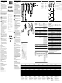
1 Adjust the distance between the sensor and the reector according to
the corresponding diagram (x = sensing range, y = operating reserve).
2 Mount the sensor and the reector using suitable mounting brackets
(see the SICK range of accessories). Align the sensor and reector with
each other.
Note the sensor's maximum permissible tightening torque of 0.8 Nm.
3 Operation in standard I / O mode (SIO):
Connection of the sensors must be carried out with the power o
(V
S
= 0 V). Depending on the connection type, the information in the
diagrams [see B] must be observed:
• Plug connection: pin assignment
• Cable: wire color
Only connect or switch on the power supply (V
S
> 0 V) after connecting
all electrical connections. The green indication LED on the sensor
illuminates.
Operation in the IO-Link mode (IOL): connect the device to a suitable
IO-Link master and integrate into the master or into the control via
IODD / function block. The green indication LED on the sensor ashes.
IODD and function block are available to download under the senor
order number at www.sick.com.
Explanations of the connection diagram (graphic B):
Switching output Q (as per graphic B):
WLG4SC-3PxxxxHAxx (PNP: load -> M)
C = communication (e. g., IO-Link) (see additional functions)
MF = multifunction (e. g., switching o senders)
4 Align sensor to suitable reector. Select position so that the red emit-
ted light beam hits the center of the reector. No light spot is visible for
infrared devices. It is only possible to identify correct alignment via the
indication LEDs. On this matter, see graphics C and E. The sensor must
have a clear view of the reector, and no object may be in the optical
path. It must be ensured that the optical openings of the sensor and
reector are completely free.
5 Sensor with teach-in pushbutton:
The sensitivity is adjusted according to table J by pressing the teach-in
pushbutton. Do not operate the teach-in pushbutton using sharp
objects.
Please refer to the enclosed operating instructions for the IO-Link pho-
toelectric sensor for information about adjusting the IO-Link sensing
range.
The sensor is adjusted and ready for operation. Refer to graphics C
and F to check the function. If the switching output fails to behave in
accordance with graphic C, check application conditions. See section
Fault diagnosis.
Additional functions
The following automation functions are available:
A70 Debouncing + Timer, A71 Debouncing + Counter, A91 TimeStamp
+ Debouncing
Debouncing = Signal debouncing (ON & OFF) via debounce time, Δt ON and
Δt OFF.
TimeStamp = Time stamp for the switching signal for product tracking
according to the SICK TimeStamp standard.
Time measurement = Measurement of the object dwell time in the light
beam or the gap between two objects. Switching signal output when the
congured reference values are reached. Output of the last absolute time
value.
Counter = Counter value increases or decreases by 1 each time an object is
detected. Switching signal output when the congured reference values are
reached. Output of the absolute counter value.
The sensor can be used in the standard I / O mode (SIO) or in the IO-Link
mode (IOL). All automation functions and other parameter settings are eec-
tive in IO-Link mode and in standard I / O mode (exception: TimeStamp). In
standard I / O mode output of the binary switching signals via pin 4 / black
wire or via pin 2 / white wire.
Information on the IO-Link functions can be found in the enclosed IO-Link
photoelectric sensors operating instructions or downloaded from
www.sick.com under the device order number.
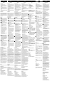
Fault diagnosis
Table H indicates which measures are to be taken if the sensor stops
working.
Disassembly and disposal
The sensor must be disposed of according to the applicable country-specic
regulations. Eorts should be made during the disposal process to recycle
the constituent materials (particularly precious metals).
Maintenance
SICK sensors are maintenance-free.
We recommend doing the following regularly:
• Clean the external lens surfaces
• Check the screw connections and plug-in connections
No modications may be made to devices.
Subject to change without notice. Specied product properties and
technical data are not written guarantees.
Deutsch
Reexions-Lichtschranke
Betriebsanleitung
Sicherheitshinweise
• Vor der Inbetriebnahme die Betriebsanleitung lesen.
• Anschluss, Montage und Einstellung nur durch Fachpersonal.
• Kein Sicherheitsbauteil gemäß EU-Maschinenrichtlinie.
• UL: Nur zur Verwendung in Anwendungen gemäß NFPA 79. Von UL
gelistete Adapter mit Anschlusskabeln sind verfügbar. Enclosure type 1.
• Gerät bei Inbetriebnahme vor Feuchte und Verunreinigung schützen.
• Diese Betriebsanleitung enthält Informationen, die während des
Lebenszyklus des Sensors notwendig sind.
Bestimmungsgemäße Verwendung
Reexions-Lichtschranke mit Zusatzoption zur Erkennung transparenter Objekte.
Die WLG4SC-3PxxxxHAxx ist eine optoelektronische Reexions-Lichtschranke
(im Folgenden Sensor genannt) und wird zum optischen, berührungslosen
Erfassen von Sachen, Tieren und Personen eingesetzt. Zur Funktion wird ein
Reektor benötigt. Bei jeder anderen Verwendung und bei Veränderungen am
Produkt verfällt jeglicher Gewährleistungsanspruch gegenüber der SICK AG.
Inbetriebnahme
1 Distanz zwischen Sensor und Reektor mit dem zugehörigen Diagramm
[vgl. H] abgleichen (x = Schaltabstand, y = Funktionsreserve).
2 Sensor und Reektor an geeignete Befestigungswinkel montieren
(siehe SICK-Zubehör-Programm). Sensor und Reektor zueinander
ausrichten.
Maximal zulässiges Anzugsdrehmoment des Sensors von 0,8 Nm beachten.
3 Betrieb im Standard I / O-Modus (SIO):
Anschluss der Sensoren muss spannungsfrei (U
V
= 0 V) erfolgen. Je
nach Anschlussart sind die Informationen in den Graken [vgl. B] zu
beachten:
• Steckeranschluss: Pinbelegung
• Leitung: Adernfarbe
Erst nach Anschluss aller elektrischen Verbindungen die Span-
nungsversorgung (U
V
> 0 V) anlegen bzw. einschalten. Am Sensor
leuchtet die grüne Anzeige-LED.
Betrieb im IO-Link-Modus (IOL): Gerät an geeigneten IO-Link-Master
anschließen und per IODD/Funktionsblock im Master, bzw. in der
Steuerung integrieren. Am Sensor blinkt die grüne Anzeige-LED. IODD
und Funktionsblock stehen unter www.sick.com unter der Sensor–
bestellnummer zum Download bereit.
Erläuterungen zum Anschlussschema (Grak B):
Schaltausgang Q (gemäß Grak B):
WLG4SC-3PxxxxHAxx (PNP: Last -> M)
C = Kommunikation (z. B. IO-Link) (siehe Zusatzfunktionen)
MF = Multifunktion (z. B. Abschaltung von Sendern)
4 Sensor auf geeigneten Reektor ausrichten. Positionierung so wählen,
dass der rote Sendelichtstrahl in der Mitte des Reektors auftrit. Bei
Infrarotgeräten ist kein Lichteck sichtbar. Die korrekte Ausrichtung
kann nur über die Anzeige-LEDs erkannt werden. Siehe dazu Graken
C und E. Der Sensor muss freie Sicht auf den Reektor haben, es darf
sich kein Objekt im Strahlengang benden. Es ist darauf zu achten,
dass die optischen Önungen von Sensor und Reektor vollständig frei
sind.
5 Sensor mit Teach-in-Taste:
Durch Drücken der Teach-in-Taste wird die Empndlichkeit gemäß
Tabelle J eingestellt. Teach-in-Taste nicht mit spitzen Gegenständen
betätigen.
Einstellung des Schaltabstandes über IO-Link bitte der beiliegenden
Betriebsanleitung IO-Link Photoelectric sensors entnehmen.
Sensor ist eingestellt und betriebsbereit. Zur Überprüfung der Funktion
Grak C und F heranziehen. Verhält sich der Schaltausgang nicht
gemäß Grak C, Einsatzbedingungen prüfen. Siehe Abschnitt Fehlerdi-
agnose.
Zusatzfunktionen
Folgende Automatisierungsfunktionen sind verfügbar:
A70 Entprellung + Zeitmessung, A71 Entprellung + Zähler, A91 TimeStamp
+ Entprellung.
Entprellung = Signal-Entprellung (Anzug & Abfall) über Entprellzeit, Δt ON
und Δt OFF.
TimeStamp = Zeitstempel zum Schaltsignal zur Produktverfolgung gemäß
SICK TimeStamp Standard.
Zeitmessung = Messung der Objektverweildauer im Lichtstrahl bzw. der
Lücke zwischen zwei Objekten. Schaltsignalausgabe bei Erreichen der
parametrierten Vergleichswerte. Ausgabe des letzten absoluten Zeitwerts.
Zähler = Erhöhung bzw. Verringerung des Zählwertes um 1 bei jeder
Objektdetektion. Schaltsignalausgabe bei Erreichen der parametrierten
Vergleichswerte. Ausgabe des absoluten Zählwertes.
Der Sensor kann im Standard I / O-Modus (SIO) oder im IO-Link-Modus
(IOL) verwendet werden. Alle Automatisierungsfunktionen und sonstigen
Parametereinstellungen sind im IO-Link-Betrieb und im Standard I / O-Betrieb
wirksam (Ausnahme: TimeStamp). Im Standard I / O-Betrieb Ausgabe der
binären Schaltsignale über Pin 4 / schwarze Ader bzw. über Pin 2 / weiße Ader.
Die IO-Link Funktionalitäten bitte der beiliegenden Betriebsanleitung
IO-Link Photoelectric sensors entnehmen oder über www.sick.com unter
der Geräte-Bestellnummer downloaden.
Fehlerdiagnose
Tabelle H zeigt, welche Maßnahmen durchzuführen sind, wenn die Funktion
des Sensors nicht mehr gegeben ist.
Demontage und Entsorgung
Die Entsorgung des Sensors hat gemäß den länderspezisch anwendbaren
Vorschriften zu erfolgen. Für die enthaltenen Wertstoe (insbesondere
Edelmetalle) ist im Rahmen der Entsorgung eine Verwertung anzustreben.
Wartung
SICK-Sensoren sind wartungsfrei.
Wir empfehlen, in regelmäßigen Abständen
• die optischen Grenzächen zu reinigen
• Verschraubungen und Steckverbindungen zu überprüfen
Veränderungen an Geräten dürfen nicht vorgenommen werden.
Irrtümer und Änderungen vorbehalten. Angegebene Produkteigenschaften
und technische Daten stellen keine Garantieerklärung dar.
Teach-in-Modus
für Objekte /
Teach-in mode
for objects
Teach-in-Zeit /
Teach-in time
Ext. Teach-in über Leitung /
Ext. Cable teach-in
Ausrichtung /
Alignment
Anzeige-LED /
LED indicator
Einstellung /
Adjustment
Schaltschwellen-
nachführung /
Continuous
threshold adaptation
1 (transparent) /
1 (transparent)
> 2 ... < 5 s ET: Pin 2 oder weiße Ader für
> 2 … < 5 s auf UV legen (PNP). /
ET: Connect pin 2 or white wire to
UV for > 2 ... < 5 s (PNP).
Sensor auf
Reflektor /
Sensor to reflector
Der Sensor erkennt
Objekte, die das
Licht mindestens
8% dämpfen (sofern
Teach-in-Modus nicht
per IO-Link-Befehl
geändert wurde) / The
sensor detects objects
that dampen the light
by at least 8% (unless
Teach-in Mode has
been changed via
IO-Link command)
Ja (sofern nicht per
IO-Link-Befehl deak-
tiviert) /
Yes (unless deactivated
via IO-Link command)
WLG4SC-
3PxxxxHAxx
-3X2xxxH / -3X3xxxH -3X1xxxH
Anzeige-LED / Fehlerbild /
LED indicator / fault pattern
Ursache /
Cause
Maßnahme /
Measures
grüne LED leuchtet nicht /
Green LED does not light up
keine Spannung oder Spannung unterhalb der
Grenzwerte /
No voltage or voltage below the limit values
Spannungsversorgung prüfen, den gesamten elektri-
schen Anschluss prüfen (Leitungen und Steckerver-
bindungen) /
Check the power supply, check all electrical connec-
tions (cables and plug connections)
grüne LED leuchtet nicht /
Green LED does not light up
Spannungsunt
erbrechungen /
Voltage interruptions
Sicherstellen einer stabilen Spannungsversorgung
ohne Unterbrechungen /
Ensure there is a stable power supply without
interruptions
grüne LED leuchtet nicht /
Green LED does not light up
Sensor
ist defekt /
Sensor is faulty
Wenn Spannungsversorgung in Ordnung ist, dann
Sensor austauschen /
If the power supply is OK, replace the sensor
grüne LED blinkt /
Green LED flashes
IO-
Link Kommunikation /
IO-Link communication
-
Schaltausgänge nicht gemäß Grafik C /
Switching outputs not according to graphic C
IO-
Link Kommunikation /
IO-Link communication
-
Schaltausgänge nicht gemäß Grafik C /
Switching outputs not according to graphic C
manuell
vorgenommene, vom Standard abweichende,
Paratmetereinstellungen /
Parameter settings made manually, which deviate from
the standard
Factory reset auslösen. Die Schaltausgänge werden
wieder auf Werkseinstellung zurückgesetzt. /
Initiate a factory reset. The switching outputs are reset
to factory settings.
gelbe LED blinkt /
Yellow LED flashes
Sensor
ist noch betriebsbereit, aber die Betriebsbe–
dingungen sind nicht optimal /
Sensor is still ready for operation, but the operating
conditions are not ideal
Betriebsbedingungen prüfen: Lichtstrahl (Lichtfleck)
vollständig auf den Reflektor ausrichten / Reinigung der
optischen Flächen (Sensor und Reflektor) / Empfindlich-
keit (Teach) neu einstellen / Reflektor eignet sich nicht
für gewählte Applikation (wir empfehlen, ausschließlich
SICK-Reflektoren zu verwenden) / Schaltabstand über-
prüfen und ggfs. anpassen, siehe Grafik E / Abstand
zwischen Sensor und Reflektor ist zu groß /
Check the operating conditions: Fully align the beam
of light (light spot) with the reflector / Clean the optical
surfaces (sensor and reflector) / Readjust the sensitivity
(teach-in) / Reflector is not suitable for the application
in question (we recommend only using SICK reflec-
tors) / Check sensing range and adjust if necessary,
see Graphic E / Distance between the sensor and the
reflector is too long
gelbe LED blinkt (nur kurz) /
Yellow LED flashes (only briefly)
Teach-in Modus /
Teach-in mode
Teach-in Modus überprüfen /
Check the teach-in mode
Signalunterbrechungen bei Objektdetektion /
Signal interruptions when object is detected
D
epolarisierende Eigenschaft der Objektoberfläche
(z. B. Folie), Umspiegelung /
Depolarizing property of the object surface
(e. g., tape), reflection
Empfindlichkeit reduzieren oder Sensorposition
verändern /
Reduce sensitivity or change the position of the sensor
Sensing range
(with reflector PL80A)
Schaltabstand
(mit Reflektor PL80A)
Portée
(avec réflecteur PL80A)
Distância de comutação
(com refletor PL80A)
Distanza di commutazione
(con riflettore PL80A)
Distancia de conmutación
(con reflector PL80A)
开关距离
(带反射器 PL80A)
最大検出範囲
(リフレクタを用いた場合PL80A)
Расстояние срабатывания
(с отражателем PL80A)
0 ... 3 m
Sensing range max.
(with reflector PL80A)
Schalt
abstand max.
(mit Reflektor PL80A)
Portée max.
(avec réflecteur PL80A)
Distância de comutação max.
(com refletor PL80A)
Distanza max. di commutazione
(con riflettore PL80A)
Distancia de conmutación max.
(con reflector PL80A)
最大开关距离
(带反射器 PL80A)
最大検出範囲
(リフレクタを用いた場合PL80A)
Расстояние срабатывания, макс.
(с отражателем PL80A)
0 ... 5 m
Light spot diameter / distance Lichtfleckdurchmesser / Entfernung Diamètre spot / distance Diâmetro do ponto de luz / distância Diametro punto luminoso / distanza Diámetro del punto luminoso / distancia
光斑直径 / 距离 光点のスポット径/距離 Диаметр светового пятна / расстояние 45 mm / 1.5 m
CTA function, selectable ON / OFF CTA Funktion, wählbar an / aus Fonction CTA, sélectionnable ON / OFF Função CTA, selecionável ativar / desativar Funzione CTA, selezionabile on / off Función CTA, opción ON / OFF CTA
功能,可选开 / 关 CTA 機能、選択可能 ON / OFF Функция CTA, выбор / отмена выбора
Supply voltage V
S
Versorgungsspannung U
V
Tension d'alimentation U
V
Tensão de alimentação U
V
Tensione di alimentazione U
V
Tensión de alimentación U
V
供电电压 U
V
供給電圧 U
v
Напряжение питания U
V
DC 10 ... 30 V
1)
Output current I
max.
Ausgangsstrom I
max.
Courant de sortie I
max.
Corrente de saída I
max.
Corrente di uscita I
max.
Intensidad de salida I
max.
输出电流 I
max.
出力電流 I
max.
Выходной ток I
макс.
≤ 100 mA
Communication mode Kommunikationsmodus Mode de communication Modo de comunicação Modalità di comunicazione Modo de comunicación
通信模式 通信モード
Режим коммуникации COM2
Max. switching frequency Schaltfolge max. Commutation max. Sequência max. de comutação Sequenza di commutazione max. Secuencia de conmutación max.
最大开关操作顺序 最大スイッチング周波数
Частота срабатывания макс. 1,000 Hz
2) 3)
Response time Ansprechzeit Temps de réponse Tempo de resposta Tempo di reazione Tiempo de respuesta
响应时间 応答時間
Время отклика 300 ... 450 μs
3) 4)
Repeatability Wiederholgenauigkeit Répétabilité Precisão de repetição Precisione della ripetizione Reproducibilidad
重复精确度 繰返し精度
Точность воспроизведения 150 μs
3)
Enclosure rating Schutzart Indice de protection Tipo de proteção Tipo di protezione Tipo de protección
防护类型 保護等級
Класс защиты
IP 66, IP 67, IP 68, IP 69K
Protection class Schutzklasse Classe de protection Classe de proteção Classe di protezione Clase de protección
防护等级 保護クラス
Класс защиты III
Circuit protection Schutzschaltungen Protections électriques Circuitos de proteção Commutazioni di protezione Circuitos de protección
保护电路 回路保護 Схемы защиты A, B, C, D
5)
Ambient operating temperature Betriebsumgebungstemperatur Température de service Temperatura ambiente de funcionamento Temperatura ambientale di funzionamento Temperatura ambiente de servicio
工作环境温度
周辺温度
(作動中) Диапазон рабочих температур -30 °C ... + 60 °C
1)
Limit value:
operation in short-circuit protection mains max. 8 A;
residual ripple max. 5 V
SS
2)
With light / dark ratio 1:1
3)
valid for Q \ on Pin2, if configured with software
4)
Signal transit time with resistive load
5)
A = V
S
-connections reverse polarity protected
B = inputs and output reverse-polarity protected
C = Interference pulse suppression
D = outputs overcurrent and short-circuit protected
1)
Grenzwerte:
Betrieb im kurzschlussgeschützten Netz max. 8 A;
R
estwelligkeit max. 5 V
SS
2)
Mit Hell- / Dunkelverhältnis 1:1
3)
gültig für Q \ auf Pin2, wenn per Software konfiguriert
4)
Signallaufzeit bei ohmscher Last
5)
A = U
V
-Anschlüsse verpolsicher
B = Ein- und Ausgänge verpolsicher
C = Störimpulsunterdrückung
D = Ausgänge überstrom- und kurzschlussfest
1)
Valeurs limites :
fonctionnement sur réseau protégé contre les courts-circuits max. 8 A ;
ondulation résiduelle max. 5 V
CC
2)
Pour un rapport clair / sombre de 1:1
3)
Valable pour Q \ sur la broche 2 en cas de configuration logicielle
4)
Temps de propagation du signal sur charge ohmique
5)
A = raccordements U
V
protégés contre les inversions de polarité
B = entrées et sorties protégées contre les inversions de polarité
C = Suppression des impulsions parasites
D = sorties protégées contre les courts-circuits et les surcharges
1)
Valores limite:
funcionamento com rede à prova de curto-circuito max. 8 A;
ondulação residual max. 5 V
SS
2)
Com proporção sombra / luz 1:1
3)
válido para Q \ no pino 2, quando configurado por software
4)
Tempo de funcionamento do sinal com carga ôhmica
5)
A = conexões protegidas contra inversão de pólos U
V
B = Entradas e saídas protegidas contra polaridade inversa
C = Supressão de impulsos parasitas
D = Saídas protegidas contra sobrecorrente e curto-circuito
1)
Valori limite:
funzionamento in rete protetta da cortocircuito max. 8 A;
ondulazione residua max. 5 V
SS
2)
Con rapporto chiaro / scuro 1:1
3)
valido per Q \ su Pin2, se configurato tramite software
4)
Durata segnale con carico ohmico
5)
A = U
V
-Allacciamenti protetti dall‘inversione di polarità
B = entrate e uscite protette da polarità inversa
C = Soppressione impulsi di disturbo
D = uscite protette da sovracorrente e da cortocircuito.
1)
Valores límite:
funcionamiento en red protegida contra cortocircuitos max. 8 A;
ondulación residual max. 5 V
SS
2)
Con una relación claro / oscuro de 1:1
3)
válido para Q \ en Pin2 si está configurado por software
4)
Duración de la señal con carga óhmica
5)
A = U
V
protegidas contra polarización inversa
B = Entradas y salidas protegidas contra polarización incorrecta
C = Represión de impulso de interferencia
D = Salidas a prueba de sobrecorriente y cortocircuitos.
1)
极限值:
在防短路电网中运行,最大 8 A;
最大余波 5 V
SS
2)
明暗比为 1:1
3)
若通过软件完成配置,则适用于针脚 2 的 Q \
4)
信号传输时间(电阻负载时)
5)
A = U
V
接口(已采取反极性保护措施)
B = 具有反极性保护的输入端和输出端
C = 消除干扰脉冲
D =
抗过载电流和抗短路输出端
1)
限界値:
短絡保護の操作は最大 8 A;
残留リップルは最大 5 V
SS
2)
ライト / ダークの比率 1:1
3)
ピン2のQ \ に有効、ソフトウェアを介して
設定する場合
4)
負荷のある信号経過時間
5)
A = U
V
接続は逆接保護
B = 入力および出力は逆接保護
C = 干渉パルス制御
D = 出力過電流および短絡保護
1)
Предельные значения:
эксплуатация в защищенной от короткого замыкания сети макс. 8 А;
остаточная волнистость макс. 5 В
SS
2)
Соотношение светлых и темных участков изображения 1:1
3)
действительно для Q \ на PIN2, если сконфигурировано
программным обеспечением
4)
Продолжительность сигнала при омической нагрузке
5)
A = U
V
-подключения с защитой от перепутывания полюсов
B = входы и выходы с защитой от перепутывания полюсов
C = подавление импульсных помех
D = выходы защищены от перенапряжения и короткого замыкания
Betriebsmodus / operation mode
Automatisierungsfunkti-
on /Automation function
SIO
Direct
1)
SIO
Logic
2)
IOL
3)
-3Pxxxx
ohne Automatisierungsfunktion /
without automation function
Ansprechzeit max. /
Max. response time
300 ... 450 μs 700 ... 850 μs 700 ... 1,000 μs
Wiederholgenauigkeit /
Repeatability
150 μs 150 μs 300 μs
Schaltfolge max. /
Max. switching frequency
1,000 Hz 1,000 Hz 900 Hz
-3PxxxxA70 Genauigkeit Zeitmessung /
Accuracy of timer
– -0.7 ... +0.7 ms ± 0.5 %
of time measurement value
-0.9 ... +0.9 ms ± 0.5 %
of time measurement value
z. B. für gemessenen Zeitwert von 1 s
e. g. for measured time value of 1 s
– -5.7 ... +5.7 ms -5.9 ... +5.9 ms
Mindestzeit zwischen zwei Prozess-Ereignissen /
Minimum time between two process events
– 500
μs 700 μs
Entprellzeit max. /
Max. debounce time
– 30,000
ms 30,000 ms
-3PxxxxA71 Schaltfolge max. /
Schaltfolge max.
– 1,000 Hz 700 Hz
Resetdauer /
Reset duration
– 1.5
ms 1.5 ms
Mindestzeit zwischen zwei Prozess-Ereignissen /
Minimum time between two process events
– 500
μs 700 μs
Entprellzeit max. /
Max. debounce time
– 30,000
ms 30,000 ms
-3PxxxxA91 Ansprechzeit max. /
Max. response time
300 ... 450 μs 750 ... 900 μs –
Genauigkeit TimeStamp /
Accuracy TimeStamp
– – -90 ... +90 μs
4)
Wiederholgenauigkeit /
Repeatability
150 μs 150 μs –
Mindestzeit zwischen zwei Prozess-Ereignissen /
Minimum time between two process events
450
μs 450 μs 750 μs
Anzahl TimeStamp-Puffer /
Number TimeStamp buffer
– – 8
Max.
Reichweite TimeStamp /
Max. sensing range TimeStamp
– – 260
ms
Entprellzeit max. /
Max. debounce time
– 52
ms 52 ms
1)
Sensorbetrieb im Standard I / O Modus ohne IO-Link Kommunikation und ohne Verwendung von sensorinternen Logik- oder Zeitparametern /
Sensor operation in standard I / O mode without IO-Link communication and without usage of sensor-internal logic or timing parameters
2)
Sensorbetrieb im Standard I / O Modus ohne IO-Link Kommunikation. Verwendung von sensorinternen Logik- oder Zeitparametern, zusätzlich Automatisierungsfunktionen /
Sensor operation in standard I / O mode without IO-Link communication. Sensor-internal logic or timing parameters plus automation functions used
3)
Sensorbetrieb mit voller IO-Link Kommunikation und Verwendung von Logik-, Zeit- und Automatisierungsfunktionsparametern /
Sensor operation with full IO-Link communication and usage of logic, timing and automation function parameters
4)
Bei ungestörter Übertragung mit einem Timestamp pro Übertragungszyklus /
For uninterrupted transmission with one timestamp per transmission cycle
1
63.2 (2.49)
23.5
(0.93)
7.5
(0.30)
22.2
(0.87)
13.1
(0.52)
0.4
(0.02)
15.3
(0.60)
2
3
1
10.7
(0.42)
48.6
(1.91)
Ø 10.8
(0.43)
M12 x 1
45 45
6
7.9
(0.31)
15.3
(0.60)
22.2
(0.87)
13.1
(0.52)
0.4
(0.02)
--------------------------------------------------------- -------------------------------------------------------
SICK AG, Erwin-Sick-Strasse 1, D-79183 Waldkirch
A B
C D
E G
J
H
I
F
Australia
Phone +61 3 9457 0600
Belgium/Luxembourg
Phone +32 (0)2 466 55 66
Brasil
Phone +55 11 3215-4900
Canada
Phone +1 905 771 14 44
Česká republika
Phone +420 2 57 91 18 50
China
Phone +86 4000 121 000
+852-2153 6300
Danmark
Phone +45 45 82 64 00
Deutschland
Phone +49 211 5301-301
España
Phone +34 93 480 31 00
France
Phone +33 1 64 62 35 00
Great Britain
Phone +44 (0)1727 831121
India
Phone +91–22–4033 8333
Israel
Phone +972-4-6801000
Italia
Phone +39 02 27 43 41
Japan
Phone +81 (0)3 5309 2112
Magyarország
Phone +36 1 371 2680
Nederland
Phone +31 (0)30 229 25 44
Österreich
Phone +43 (0)22 36 62 28 8-0
Norge
Phone +47 67 81 50 00
Polska
Phone +48 22 837 40 50
România
Phone +40 356 171 120
Russia
Phone +7-495-775-05-30
Schweiz
Phone +41 41 619 29 39
Singapore
Phone +65 6744 3732
Slovenija
Phone +386 (0)1-47 69 990
South Africa
Phone +27 11 472 3733
South Korea
Phone +82 2 786 6321/4
Suomi
Phone +358-9-25 15 800
Sverige
Phone +46 10 110 10 00
Taiwan
Phone +886-2-2375-6288
Türkiye
Phone +90 (216) 528 50 00
United Arab Emirates
Phone +971 (0) 4 8865 878
USA/México
Phone +1(952) 941-6780
BZ int43
Please find detailed addresses and additional representatives and agencies in
all major industrial nations at www.sick.com
8017605.YMV9 0715 COMAT
Seite wird geladen ...
-
 1
1
-
 2
2


SICK WLG4SC-3PxxxxHAxx Bedienungsanleitung
- Typ
- Bedienungsanleitung
in anderen Sprachen
- English: SICK WLG4SC-3PxxxxHAxx Operating instructions
- français: SICK WLG4SC-3PxxxxHAxx Mode d'emploi
- español: SICK WLG4SC-3PxxxxHAxx Instrucciones de operación
- italiano: SICK WLG4SC-3PxxxxHAxx Istruzioni per l'uso
- русский: SICK WLG4SC-3PxxxxHAxx Инструкция по эксплуатации
- português: SICK WLG4SC-3PxxxxHAxx Instruções de operação
- 日本語: SICK WLG4SC-3PxxxxHAxx 取扱説明書
Verwandte Artikel
-
SICK WLG4SC-3PxxxxAxx Bedienungsanleitung
-
-
-
-
-
-
-
-
-