
ARMO
ARMO

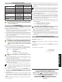
Fig. 1
Fig. 1

Fig. 3 Fig. 4
Fig. 5
Fig. 7
Fig. 6
Fig. 8

Fig. 10Fig. 9
Fig. 11 Fig. 12

1
ITALIANO
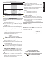
1. CARATTERISTICHE TECNICHE
ARMO 24V ARMO 230V
Tensione di Alimenta-
zione
24 Vdc
24 V~
115 - 230 V~
(+6% -10%)
Carico Max Contatti 100 mA 15 A
Numero Micro 22
Tipo di Contatti NC/NO - NC/NO NC/NO - NC/NO
Grado IP 55 55
Serratura
Standard DIN
18252
41,5 - 45 mm
Standard DIN
18252
41,5 - 45 mm
Corsa di Sblocco 25 mm 25 mm
Installazione A parete A parete
Non rimuovere il tappo di sicurezza, evidenziato in
Fig. 11, prima che sia espressamente indicato nella
procedura di installazione.
2. INSTALLAZIONE
Per installare il dispositivo ARMO attenersi alle fasi di seguito
riportate:
Posizionare il dispositivo in prossimità dell’automazione
da pilotare/sbloccare. Prestare attenzione agli ingombri
del dispositivo riportati in Fig. 1;
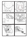
In Fig. 3 è mostrato il retro del dispositivo evidenzian-
do l’asola per il passaggio dei cavi elettrici ( rif. ) e
l’alloggiamento per il cavo di trazione per lo sbocco
manuale ( rif. );
Utilizzare il dispositivo stesso per segnare i riferimenti a pa-
rete dei fori da effettuare come indicato in Fig.4 rif ;
Accertarsi che il foro di passaggio dei cavi elettrici e
del cavo di sblocco sia di diametro non inferiore a
40 mm e che risulti posizionato come indicato in Fig.4
rif .
Fissare a muro il dispositivo;
Collegare i cavi elettrici provenienti dall’automazione
nelle apposite morsettiere dei micro interruttori (Fig.5)
in funzione della tipologia del comando:
NO = Normalmente APERTO
NC = Normalmente CHIUSO
C = COMUNE
rif. = Attacco per il cavo di TERRA
L’ ARMO non deve essere in alcun modo utilizzato come
scatola di derivazione!
Inserire il cavo di sblocco senza guaina all’interno del-
l’apposito foro come indicato in Fig.6 rif. , attraversan-
do anche il tensionatore ( rif. );
Prima di serrare il cavo di sblocco sul tensionatore portare
il tensionatore stesso a fine corsa come mostrato in Fig.
6 rif agendo sulla testa della vite di regolazione con
una chiave esagonale;
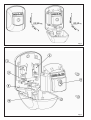
Accertarsi che lo sportello del dispositivo sia mante-
nuto aperto dalla Leva di Blocco rossa rif. di Fig.2
prima di procedere al serraggio del cavo sul tensio-
natore.
Utilizzando un paio di pinze, mettere in tensione il cavo
SENZA SBLOCCARE L’OPERATORE collegato, serrare poi il
cavo di sblocco sul tensionatore con l’apposita vite;
Agendo sulla testa della vite di regolazione con una
chiave esagonale muovere il tensionatore fino a sbloc-
care l’operatore collegato come mostrato in Fig.7 rif.
;
Tagliare il cavo in eccedenza all’uscita del tensiona-
tore;
Se non presente, inserire la serratura conforme allo stan-
dard DIN 18252 e la sua guarnizione sulla parte frontale
del dispositivo come mostrato in Fig.8;
1.
2.
3.
4.
5.
6.
7.
8.
9.
10.
11.
Per agevolare l’inserimento della serratura schiac-
ciare le estremità superiori delle leve di azionamento
micro come indicato in Fig. 8 rif. .
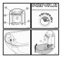
Fissare la serratura così inserita con l’apposita piastrina
e viti a corredo (Fig. 8);
Unire la parte frontale con la parte fissata al muro ser-
rando le quattro viti autoformanti in Fig. 9 rif. , prestare
attenzione a disporre i cavi provenienti dai micro come
in Fig. 6 onde evitare il loro schiacciamento;
Controllare l’attivazione dei micro interruttori ruotando
la chiave nella serratura secondo lo schema riportato
in Fig. 10:
A = azionamento micro rif. in Fig.2
B = azionamento micro rif. in Fig.2
C = sgancio leva di sblocco
Controllare che la posizione C corrisponda alla scom-
parsa del pistoncino rif. in Fig. 9 all’interno del
corpo del dispositivo.
Una volta controllato l’azionamento del pistoncino di
sgancio da serratura rimuovere il tappo di sicurezza dalla
leva di sblocco come indicato in Fig.11;
Chiudere il dispositivo sollevando prima la Leva di Blocco
rossa e poi la Leva di Sblocco a chiusura del dispositivo
come indicato in Fig.12.
DICHIARAZIONE CE DI CONFORMITÁ
Fabbricante: GENIUS S.p.A.
Indirizzo: Via Padre Elzi, 32 - 24050 - Grassobbio- Bergamo
- ITALIA
Dichiara che: Il dispositivo ARMO è conforme alla Direttiva
Bassa Tensione 2006/95/CE.
Grassobbio,
23 Aprile 2008
L’Amministratore Delegato
D. Gianantoni
12.
13.
14.
15.
16.
Note per la lettura dell’istruzione
Leggere completamente questo manuale di
installazione prima di iniziare l’installazione del
prodotto.
Il simbolo
evidenzia note importanti per la sicurezza
delle persone e l’integrità dell’automazione.
Il simbolo richiama l’attenzione su note riguardanti
le caratteristiche od il funzionamento del prodotto.

2
ENGLISH
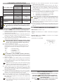
1. TECHNICAL SPECIFICATIONS
ARMO 24V ARMO 230V
Power supply voltage
24 Vdc
24 V~
115 - 230 V~
(+6% -10%)
Contacts max. Load 100 mA 15 A
Nr. of microswitches 22
Type of Contacts NC/NO - NC/NO NC/NO - NC/NO
IP Class 55 55
Lock
Standard DIN
18252
41,5 - 45 mm
Standard DIN
18252
41,5 - 45 mm
Release Travel 25 mm 25 mm
Installation On-wall On-wall
Do not remove the safety plug shown in Fig.11, before
this is expressly indicated in the installation procedu-
re.
2. INSTALLATION
To install the ARMO device, observe the following steps:
Position the device near the automated system to be
piloted/released. Take into consideration the overall
dimensions shown in Fig. 1;
Fig. 3 shows the rear of the device, indicating the slot for
routing the electric cables ( ref. ) and the housing of
the traction cable for manual release ( ref. );
Use the device to mark the on-wall references of the
holes, as shown in Fig.4 ref. ;
Make sure that the hole for routing the electric cables
and the release cable, has a diameter of not less than
40 mm and is positioned as shown in Fig. 4 ref.
Secure the device on a wall;
Connect the electric cables coming from the auto-
mated system to the relevant terminal-boards of the
microswitches (Fig.5) according to the type of com-
mand:
NO = Normally OPEN
NC = Normally CLOSED
C = COMMON
rif. = EARTH cable fitting
It’s forbidden to use the ARMO as electric shunt box!
Fit the release cable, without a sheath, inside the hole as
shown in Fig. 6 ref. , crossing also over the tensioning
device ( ref. );
Before you tighten the release cable on the tensioning
device, take the device to the travel limit, as shown in
Fig. 6 ref. , turning the head of the adjusting screw with
a hexagon wrench;
Make sure that the door of the XK 21 device is kept
open by the red Locking Lever ref. d in Fig.2, before
tightening the cable on the tensioning device.
Using a pair of pincers, apply tension to the cable
WITHOUT RELEASING the connected OPERATOR, and
then tighten the release cable on the tensioning device
with the relevant screw;
Turning the head of the adjustment screw with a hexagon
wrench, move the tensioning device until you release the
operator, connected as shown in Fig. 7 ref. ;
Cut excess cable at the exit of the tensioning device;
If it is not present, fit the lock, conforming to standard
DIN 18252 and its gasket on the front of the device as
shown in Fig. 8;
To facilitate fitting the lock, push down the top ends
of the levers activating the microswitches as shown
in Fig. 8 ref. .
1.
2.
3.
4.
5.
6.
7.
8.
9.
10.
11.
Fasten the lock, inserted as above, with the supplied
plate and screws ( Fig.8 );
Join the front part to the part secured to the wall, ti-
ghtening the four self-forming screws as shown in Fig. 9
ref. , take care when laying the cables coming from
the microswitches, as shown in Fig. 6 in order to avoid
any squeezing;
Check activation of the microswitches, turning the key
in the lock according to the diagram in Fig.10:
A = activation of microswitch ref. in Fig.2
B = activation of microswitch ref. in Fig.2
C = detachment of release lever
Check if position C corresponds to the disappearance
of the piston ref. in Fig.9, inside the body of the
device.
When you have checked the activation of the lock
release piston, remove the safety plug from the release
lever as shown in Fig. 11;
Close the device, first lifting the red Locking Lever, and
then the Release Lever to close the device as shown in
Fig. 12.
CE DECLARATION OF CONFORMITY
Manufacturer: GENIUS S.p.A.
Address: Via Padre Elzi, 32 - 24050 - Grassobbio- Bergamo
- ITALY
Declares that: Device ARMO is conforms to Low Voltage
Directive 2006/95/CE.
Grassobbio, 23 April 2008
Managing Director
D. Gianantoni
12.
13.
14.
15.
16.
Notes on reading the instruction
Read this installation manual to the full before you begin
installing the product.
The symbol
indicates notes that are important for
the safety of persons and for the good condition of the
automated system.
The symbol
draws your attention to the notes on the
characteristics and operation of the product.

3
FRANÇAIS
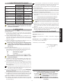
1. CARACTÉRISTIQUES TECHNIQUES
ARMO 24V ARMO 230V
Tension d’ Alimenta-
tion
24 Vcc
24 V~
115 - 230 V~
(+6% -10%)
Charge Maxi Con-
tacts
100 mA 15 A
Nombre micro-inter-
rupteurs
22
Type de contacts NF/NO - NF/NO NF/NO - NF/NO
Degré IP 55 55
Serrure
Standard
DIN 18252
41,5 - 45 mm
Standard
DIN 18252
41,5 - 45 mm
Course de Déverrouil-
lage
25 mm 25 mm
Installation Murale Murale
Ne pas enlever le bouchon de sécurité illustré dans
la Fig. 11, avant l’indication expresse au cours de la
procédure d’installation.
2. INSTALLATION
Pour installer le dispositif ARMO s’en tenir aux phases re-
portées ci-après:
Positionner le dispositif à proximité de l’automatisme
à piloter/déverrouiller. Veiller aux encombrements du
dispositif indiqués dans la Fig. 1;
La Fig. 3 illustre l’arrière du dispositif en indiquant la rai-
nure de passage des câbles électriques ( réf. ) et le
logement du câble de traction pour le déverrouillage
manuel ( réf. );
Utiliser le dispositif pour marquer les références au mur
des trous à réaliser d’après la Fig. 4 réf. ;
S’assurer que le trou de passage des câbles électriques
et du câble de déverrouillage a un diamètre non
inférieur à 40 mm et qu’il est positionné d’après la
Fig.4 réf. .
Fixer le dispositif au mur;
Raccorder les câbles électriques en provenance de
l’automatisme sur les borniers des micro-interrupteurs
(Fig. 5) en fonction du type de commande:
NO = Normalement OUVERT
NC = Normalement FERMÉ
C = COMMUN
rif. =
Patte d’attache pour le câble de TERRE
Il est formellement interdit d’utiliser l’ARMO comme
boîte de dérivation!
Introduire le câble de déverrouillage sans gaine à l’in-
térieur du trou spécifique d’après la Fig.6 réf. , traver-
sant également le tendeur ( réf. );
Avant de serrer le câble de déverrouillage sur le tendeur,
amener le tendeur en fin de course d’après la Fig. 6 réf.
en agissant sur la tête de la vis de réglage avec une
clé hexagonale;
S’assurer que le capot du dispositif est maintenu ou-
vert par le levier de Blocage rouge réf. Fig.2 avant
de serrer le câble sur le tendeur.
Avec une paire de pinces, tendre le câble SANS DÉVER-
ROUILLER L’OPÉRATEUR raccordé, puis serrer le câble de
déverrouillage sur le tendeur avec la vis spécifique;
En agissant sur la tête de la vis de réglage avec une clé
hexagonale, actionner le tendeur jusqu’au déverrouilla-
ge de l’opérateur connecté d’après la Fig.7 réf. ;
Couper le câble en excès à la sortie du tendeur;
En l’absence de tendeur, introduire la serrure conforme
au standard DIN 18252 et son joint à l’avant du dispositif
d’après la Fig. 8;
1.
2.
3.
4.
5.
6.
7.
8.
9.
10.
11.
Pour faciliter l’introduction de la serrure, écraser les
extrémités supérieures des leviers d’actionnement
des micro-interrupteurs d’après la Fig.8 réf. .
Fixer la serrure ainsi introduite avec la plaquette et les
vis fournies (Fig. 8);
Unir la partie frontale et la partie fixe au mur en serrant les
quatre vis autoformeuses Fig. 9 réf. p, Veiller à disposer les
câbles en provenance des micro-interrupteurs d’après
la Fig. 6 pour éviter leur écrasement;
Contrôler l’activation des micro-interrupteurs en tournant
la clé dans la serrure d’après le schéma présent dans
la Fig. 10:
A = actionnement micro-interrupteur réf. Fig.2
B = actionnement micro-interrupteur réf. Fig.2
C = déclenchement levier de déverrouillage
Contrôler que la position C correspond à la disparition
du piston réf. Fig. 9 à l’intérieur du corps du dispo-
sitif.
Après avoir contrôlé l’actionnement du piston de
déclenchement à partir de la serrure, enlever le bou-
chon de sécurité du levier de déverrouillage d’après
la Fig.11;
Fermer le dispositif en soulevant d’abord le Levier de
Blocage rouge et puis le Levier de Déverrouillage pour
fermer le dispositif d’après la Fig.12.
DÉCLARATION CE DE CONFORMITÉ
Fabricant: GENIUS S.p.A.
Adresse: Via Padre Elzi, 32 - 24050 - Grassobbio- Bergamo
- ITALIE
Déclare que: Le dispositif ARMO est conforme à la Directive
pour Basse Tension 2006/95/CE.
Grassobbio, le 23 Avril 2008
L’Administrateur Délégué
D. Gianantoni
12.
13.
14.
15.
16.
Remarques pour la lecture de l’instruction
Lire ce manuel d’installation dans son ensemble avant
de commencer l’installation du produit.
Le symbole
souligne des remarques importantes
pour la sécurité des personnes et le parfait état de
l’automatisme.
Le symbole attire l’attention sur des remarques
concernant les caractéristiques ou le fonctionnement
du produit.

4
ESPAÑOL
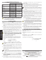
1. CARACTERÍSTICAS TÉCNICAS
ARMO 24V ARMO 230V
Tensión deAlimenta-
ción
24 Vdc
24 V~
115 - 230 V~
(+6% -10%)
Carga Máxima Con-
tactos
100 mA 15 A
Número Microinter-
ruptores
22
Tipo de Contactos NC/NA - NC/NA NC/NA - NC/NA
Grado IP 55 55
Cerradura
Standard
DIN 18252
41,5 - 45 mm
Standard
DIN 18252
41,5 - 45 mm
Carrera de desblo-
queo
25 mm 25 mm
Instalación En pared En pared
No retire el tapón de seguridad evidenciado en la
Fig. 11, antes de que se indique expresamente en el
procedimiento de instalación.
2. INSTALACIÓN
Para instalar el dispositivo ARMO proceda del siguiente
modo:
Coloque el dispositivo cerca del automatismo que se
quiere controlar/desbloquear. Preste atención a las
dimensiones totales del dispositivo, que se indican en
la Fig. 1;
En la Fig. 3 se muestra la parte trasera del dispositivo en
la que se destaca la ranura para el paso de los cables
eléctricos ( ref. ) y el alojamiento para el cable de
tracción para el desbloqueo manual ( ref. );
Utilice el mismo dispositivo para marcar en la pared la
posición de los orificios que deberá realizar, tal y como
se indica en la Fig.4 ref. ;
Asegúrese de que el orificio de paso de los cables
eléctricos y del cable de desbloqueo tenga un diá-
metro no inferior a 40 mm, y que esté posicionado
como se indica en la Fig.4 ref. .
Fije el dispositivo en la pared;
Conecte los cables eléctricos en salida del automa-
tismo en las correspondientes regletas de bornes de
los microinterruptores (Fig.5), en función del tipo de
mando:
NO = Normalmente ABIERTO
NC = Normalmente CERRADO
C = COMÚN
rif. = Conexión para el cable de TIERRA
Es prohibido utilizar el ARMO como caja de deriva-
ciòn!
Inserte el cable de desbloqueo sin vaina dentro del
orificio, como se indica en la Fig.6 ref. , atravesando
también el tensor ( ref. );
Antes de apretar el cable de desbloqueo en el tensor,
coloque el tensor a final de carrera, como se indica en
la Fig.6 ref. , y manipule el tornillo de reglaje con una
llave hexagonal;
Asegúrese de que la portezuela del dispositivo se
mantenga abierta gracias a la Palanca de Bloqueo
roja ref. de Fig.2 antes de apretar el cable en el
tensor.
Utilizando un par de pinzas, tense el cable SIN DESBLO-
QUEAR EL OPERADOR conectado, seguidamente apriete
el cable de desbloqueo en el tensor con el correspon-
diente tornillo;
Con una llave hexagonal manipule la cabeza del tor-
nillo de reglaje y mueva el tensor hasta desbloquear
1.
2.
3.
4.
5.
6.
7.
8.
9.
el operador conectado, tal y como se muestra en la
Fig.7 ref. ;
Corte el cable sobrante a la salida del tensor;
Si no estuviera presente, coloque la cerradura conforme
con el estándar DIN 18252 y su junta en la parte frontal
del dispositivo, como se muestra en la Fig.8;
Para facilitar la inserción de la cerradura, apriete el
extremo superior de las palancas de accionamiento
de los microinterruptores, como se indica en la Fig.8
ref. .
Fije la cerradura ya insertada con la placa y los tornillos
suministrados en dotación ( Fig.8 );
Una la parte frontal con la parte fijada a la pared y
apriete los cuatro tornillos con rosca autoformante como
se muestra en la Fig. 9 ref. , preste atención a colocar
los cables en salida del micro como se indica en la Fig.
6, a fin de evitar que se aplasten;
Compruebe la activación de los microinterruptores
girando la llave en la cerradura según el esquema
indicado en la Fig. 10:
A = accionamiento microinterruptor ref. en Fig.2
B = accionamiento microinterruptor ref. en Fig.2
C = desenganche de la palanca de desbloqueo
Compruebe que la posición C corresponda a la posi-
ción retráctil del pistón (ref. en Fig. 9) en el interior
del cuerpo del dispositivo.
Una vez comprobado el accionamiento del pistón de
desenganche de la cerradura, retire el tapón de segu-
ridad de la palanca de desbloqueo como se indica
en la Fig.11;
Cierre el dispositivo levantando antes la palanca de blo-
queo roja y luego la palanca de desbloqueo de cierre
del dispositivo, tal y como se indica en la Fig.12.
DECLARACIÓN CE DE CONFORMIDAD
Fabricante: GENIUS S.p.A.
Dirección: Via Padre Elzi, 32 - 24050 - Grassobbio- Bergamo
- ITALIA
Declara que: El dispositivo ARMO cumple con la Directiva
De Baja Tensión 2006/95/CE.
Grassobbio, 23 de Abril de 2008
El Administrador Delegado
D. Gianantoni
10.
11.
12.
13.
14.
15.
16.
Notas para la lectura de las instrucciones
Leer completamente este manual antes de empezar la
instalación del producto.
El símbolo
destaca notas importantes para la
seguridad de las personas y la integridad de la
automación.
El símbolo
evidencia notas sobre las características
o el funcionamiento del producto.

5
DEUTSCH
1. TECHNISCHE DATEN
ARMO 24V ARMO 230V
Versorgungsspan-
nung
24 Vdc
24 V~
115 - 230 V~
(+6% -10%)
Max. Last Kontakte 100 mA 15 A
Anzahl Mikro 22
Art der Kontakte NC/NO - NC/NO NC/NO - NC/NO
Schutzart IP 55 55
Schloss
Standard
DIN 18252
41,5 - 45 mm
Standard
DIN 18252
41,5 - 45 mm
Entriegelungshub 25 mm 25 mm
Montage an der Wand an der Wand
Die Sicherheitsabdeckung (Abb. 11) erst dann entfer-
nen, wenn dies ausdrücklich in den Montageanwei-
sungen angegeben ist.
2. MONTAGE
Für die Montage der Vorrichtung ARMO sind die nachfol-
genden Schritte auszuführen:
Die Vorrichtung in der Nähe der zu steuernden/zu entrie-
gelnden Automation positionieren. Die Abmessungen
der Vorrichtungen laut Fig. 1 berücksichtigen;
In der Fig. 3 ist die Rückseite der Vorrichtung mit dem Lan-
gloch für den Durchzug der Stromkabel (Bez. ) und der
Aufnahme für das Zugkabel zur manuellen Entriegelung
( Bez. ) abgebildet;
Zum Anzeichnen der Referenzpunkte für die Bohrungen
an der Wand die Vorrichtung verwenden (siehe Fig. 4,
Bez. );
Sicherstellen, dass die Bohrung für den Durchzug der
Stromkabel und des Entriegelungskabels einen Dur-
chmesser von mindestens 40 mm aufweist und ent-
sprechend den Angaben in Fig. 4 Bez. ausgebildet
wird.
Die Vorrichtung an der Wand befestigen;
Die von der Automation ausgehenden Stromkabel an
den entsprechenden Klemmleisten der Mikroschalter
(Fig. 5) je nach Art der Schaltung anschließen
NO = SCHLIESSER
NC = ÖFFNER
C = SAMMELKONTAKT
rif. = Anschluss für das ERDUNGSKABEL
Die Vorrichtung ARMO nie als Abzweigdose verwen-
den!
Das Entriegelungskabel ohne Ummantelung in die en-
tsprechende Öffnung (siehe Fig. 6 Bez. ) durch den
Spanner ( Bez. ) einführen;
Vor dem Festspannen des Entriegelungskabels am Span-
ner einen Sechskantschlüssel am Kopf der Stellschraube
ansetzen und den Spanner bis zum Endanschlag schie-
ben (siehe Fig. 6 Bez. );
Vor dem Festspannen des Kabels am Spanner si-
cherstellen, dass die Klappe der Vorrichtung durch
den roten Verriegelungshebel (Fig. 2, Bez. ) offen
beibehalten wird.
Das Kabel mit einer Zange spannen, OHNE DEN ange-
schlossenen ANTRIEB ZU ENTRIEGELN. Dann das Freiga-
bekabel mit der entsprechenden Schraube am Spanner
festspannen;
Einen Sechskantschlüssel an den Kopf der Stellschraube
ansetzen und den Spanner so weit bewegen, bis der
angeschlossene Antrieb entriegelt ist (siehe Fig. 7, Bez.
);
Das überstehende Kabel am Ausgang des Spanners
abschneiden;
1.
2.
3.
4.
5.
6.
7.
8.
9.
10.
Soweit nicht bereits vorhanden, das Schloss nach DIN
18252 und die entsprechende Dichtung an der Vor-
derseite der Vorrichtung laut Darstellung in der Fig. 8
einsetzen;
Um das Schloss leichter einsetzen zu können, die
oberen Enden der Hebel zur Mikrobetätigung laut
Angaben in der Fig. 8 Bez. zusammendrücken.
Das so eingesetzte Schloss mit der entsprechenden
Scheibe und den Schrauben (im Lieferumfang enthal-
ten) befestigen (Fig. 8);
Den frontseitigen Teil mit dem an der Wand befestigten
Teil verbinden und hierzu die vier selbstschneidenden
Schrauben (Fig. 9 Bez. ) festziehen, Auf die Verlegung
der Kabel aus den Mikroschaltern (siehe Fig. 6) beachten,
um das Quetschen zu verhindern;
Sicherstellen, dass die Mikroschalter ansprechen und
hierzu den Schlüssen nach dem Schema laut Fig. 10 im
Schloss drehen:
A = Betätigung Mikro Bez. (Fig. 2)
B = Betätigung Mikro Bez. (Fig. 2)
C = Abwurf des Lösungshebels
Sicherstellen, dass der Kolben (Fig. 9, Bez. ) im Körper
der Vorrichtung an der Position C ausfährt.
Nach der Prüfung der Betätigung des Kolbens zur Frei-
gabe vom Schloss die Sicherheitsabdeckung des Entrie-
gelungshebels laut Fig. 11 entfernen;
Die Vorrichtung verschließen und hierzu zuerst den roten
Verriegelungshebel und dann den Entriegelungshebel
zum Schließen der Vorrichtung laut Angaben in Fig. 12
anheben.
CE-KONFORMITÄTSERKLÄRUNG
Hersteller: GENIUS S.p.A.
Adresse: Via Padre Elzi, 32 - 24050 - Grassobbio- Bergamo
- ITALIEN
erklärt, dass: die Sicherheitsvorrichtung ARMO der Richtlinie
2006/95/CE.
Grassobbio, 23 April 2008
Geschäftsführer
D. Gianantoni
11.
12.
13.
14.
1.
2.
Hinweise zu den Anleitungen
Vor der Installation des Produkts sind die
Installationsanweisungen vollständig zu lesen.
Mit dem Symbol
sind wichtige Anmerkungen für die
Sicherheit der Personen und den störungsfreien Betrieb
der Automation gekennzeichnet.
Mit dem Symbol wird auf Anmerkungen zu
den Eigenschaften oder dem Betrieb des Produkts
verwiesen.

6
NEDERLANDS
1. TECHNISCHE EIGENSCHAPPEN
ARMO 24V ARMO 230V
Voedingsspanning
24 Vdc
24 V~
115 - 230 V~
(+6% -10%)
Max. belasting con-
tacten
100 mA 15 A
Aantal microschake-
laars
22
Soort contacten NC/NO - NC/NO NC/NO - NC/NO
IP-graad 55 55
Slot
Standaard
DIN 18252
41,5 - 45 mm
Standaard
DIN 18252
41,5 - 45 mm
Slaglengte ontgren-
deling
25 mm 25 mm
Installatie Wandmodel Wandmodel
De in Fig. 11 aangeduide veiligheidsdop mag niet
worden verwijderd voordat dat uitdrukkelijk is aan-
gegeven in de installatieprocedure.
2. INSTALLATIE
Om de voorziening ARMO te installeren moeten de hieron-
der aangegeven fasen worden gevolgd:
Plaats de voorziening vlakbij het te sturen/ontgrendelen
automatisch systeem. Let op de in Fig. 1 aangegeven
afmetingen van de voorziening;
In Fig. 3 wordt de achterkant van de voorziening ge-
toond, met de aanduiding van het gat waar de elek-
triciteitskabels doorheen moeten ( ref. ), en de holte
voor de trekkabel van de handmatige ontgrendeling
( ref. );
Gebruik de voorziening om op de wand te markeren
waar de gaten moeten worden geboord, zoals aange-
geven in Fig. 4 ref. ;
Controleer of de doorgang voor de elektriciteitskabels
en het gat voor de ontgrendelingskabel een diameter
hebben van minstens 40 mm, en op de plaats zitten
die is aangegeven in Fig.4 ref .
Bevestig de voorziening aan de muur;
Sluit de elektriciteitskabels die van het automatisch
systeem afkomstig zijn aan op de speciale klemmenbor-
den van de microschakelaars (Fig. 5) afhankelijk van het
soort commando:
NO = Normaal OPEN
NC = Normaal GESLOTEN
C = GEMEENSCHAPPELIJKE AANSLUITING
rif. = Aansluiting voor AARDINGskabel
De ARMO mag op geen enkele wijze worden gebruikt
als aftakdoos!
Steek de ontgrendelingskabel zonder omhulsel in het
speciale gat, zoals aangegeven in Fig. 6 ref. , en daar-
mee ook door de spaninrichting ( ref. );
Zet alvorens de ontgrendelingskabel op de spaninri-
chting vast te zetten de inrichting zelf helemaal op het
einde zijn slaglengte, zoals aangegeven in Fig. 6 ref.
, door met een zeskantsleutel aan de regelschroef
te draaien;
Controleer of het deurtje van de voorziening open
wordt gehouden door de rode vergrendelingshendel,
ref. in Fig.2, alvorens de kabel op de spaninrichting
vast te zetten.
Zet met behulp van een tang de kabel onder spanning
ZONDER de daarop aangesloten AANDRIJVING TE ON-
TGRENDELEN, en zet de ontgrendelingskabel vervolgens
vast met de speciale schroef;
Beweeg de spaninrichting door met een zeskantsleutel
1.
2.
3.
4.
5.
6.
7.
8.
9.
aan de kop van de regelschroef te draaien, tot de daa-
rop aangesloten aandrijving wordt ontgrendeld, zoals
getoond in Fig. 7 ref. ;
Snijd het overtollige deel van de kabel eraf bij de uitgang
van de spaninrichting;
Als er geen slot is, plaats er dan een conform de stan-
daard DIN 18252 en de bijbehorende dichting op de
voorkant van de voorziening, zoals getoond in Fig. 8;
Druk, om het slot er beter in te krijgen, op de bo-
venste uiteinden van de inschakelhendels van de
microschakelaars zoals aangegeven in Fig. 8 ref. .
Bevestig het er zo in gezette slot met het plaatje en de
schroeven (bijgeleverd) ( Fig. 8 );
Bevestig de voorkant op het aan de muur bevestigde
deel door de vier draadvormende schroeven vast te
draaien Fig. 9 ref. , let goed op bij het plaatsen van
de kabels afkomstig van de microschakelaars, zoals in
Fig. 6, om te voorkomen dat ze worden geplet;
Controleer of de microschakelaars worden ingeschakeld
als de sleutel van het slot wordt gedraaid volgens het
schema in Fig. 10:
A = inschakeling microschakelaars ref. in Fig.2
B = inschakeling microschakelaars ref. in Fig.2
C = loskoppelen ontgrendelingshendel
Controleer of de positie C overeenkomt met het verd-
wijnen van het zuigertje ref. in Fig. 9 in de behuizing
van de voorziening.
Verwijder, als eenmaal is nagegaan dat het ontgren-
delingszuigertje wordt ingeschakeld, de veiligheidsdop
van de ontgrendelingshendel, zoals aangegeven in
Fig. 11;
Sluit de voorziening door eerst de rode vergrendelin-
gshendel en vervolgens de ontgrendelingshendel voor
het sluiten van de voorziening omhoog te zetten, zoals
aangegeven in Fig. 12.
CE VERKLARING VAN OVEREENSTEMMING
Fabrikant: GENIUS S.p.A.
Adres: Via Padre Elzi, 32 - 24050 - Grassobbio- Bergamo
- ITALIE
Verklaart dat: De voorziening ARMO conform is aan de
richtlijn 2006/95/CE.
Grassobbio, 23 April 2008
De Algemeen Directeur
D. Gianantoni
10.
11.
12.
13.
14.
15.
16.
Opmerkingen voor het lezen van de instructies
Lees deze installatiehandleiding aandachtig door
alvorens te beginnen met de installatie van het product.
Het symbool
is een aanduiding voor belangrijke
opmerkingen voor de veiligheid van personen en om het
automatische systeem in goede staat te houden.
Het symbool vestigt de aandacht op opmerkingen
over de eigenschappen of de werking van het product.

NOTE - NOTES - NOTE - NOTAS - ANMERKUNG - OPMERKINGEN

Le descrizioni e le illustrazioni del presente manuale non sono impegnative. GENIUS si riserva il diritto, lasciando inal-
terate le caratteristiche essenziali dell’apparecchiatura, di apportare in qualunque momento e senza impegnarsi
ad aggiornare la presente pubblicazione, le modifiche che essa ritiene convenienti per miglioramenti tecnici o per
qualsiasi altra esigenza di carattere costruttivo o commerciale.
The descriptions and illustrations contained in the present manual are not binding. GENIUS reserves the right, whils
leaving the main features of the equipments unaltered, to undertake any modifications to holds necessary for either
technical or commercial reasons, at any time and without revising the present publication.
Les descriptions et les illustrations du présent manuel sont fournies à titre indicatif. GENIUS se réserve le droit d’apporter
à tout moment les modifications qu’elle jugera utiles sur ce produit tout en conservant les caractéristiques essentielles,
sans devoir pour autant mettre à jour cette publication .
Las descripciones y las ilustraciones de este manual no comportan compromiso alguno. GENIUS se reserva el de-
recho, dejando inmutadas las características esenciales de los aparatos, de aportar, en cualquier momento y sin
comprometerse a poner al día la presente publicación, todas las modificaciones que considere oportunas para el
perfeccionamiento técnico o para cualquier otro tipo de exigencia de carácter constructivo o comercial.
Timbro rivenditore: / Distributor’s stamp: / Timbre de l’agent: / Sello del revendedor: / Fachhändlerstempel: / Stem-
pel dealer:
Via Padre Elzi, 32
24050 - Grassobbio
BERGAMO-ITALY
tel. 0039.035.4242511
fax. 0039.035.4242600
www.geniusg.com
00058I0764 Rev.0
-
 1
1
-
 2
2
-
 3
3
-
 4
4
-
 5
5
-
 6
6
-
 7
7
-
 8
8
-
 9
9
-
 10
10
-
 11
11
-
 12
12


in anderen Sprachen
- français: Genius ARMO Mode d'emploi
- español: Genius ARMO Instrucciones de operación
- italiano: Genius ARMO Istruzioni per l'uso
- Nederlands: Genius ARMO Handleiding