
62403–05.04
00062403
Power-Cap für
High-Power-Endstufe
Hama GmbH & Co KG
Dresdner Str. 9
86653 Monheim/Bayern GERMANY
Tel. +49 (0) 9091 /502-0
Fax +49 (0)9091/502-274
www.hama.de
www.hama.de

3
• Coole zylindrische Bauform in Silber
• 1 Farad max. 20V Gleichspannung
• integrierte digitale Spannungsanzeige
• 1 Status LED als Lade-/Entlade- Funktions Anzeige
• optische und akustische Verpolungsanzeige
• Remoteanschluss
• Inkl. speziellem Ladekabel mit integriertem 100 Ohm Widerstand
• Inkl. 2 Kunststoffhalter transparent
• E-geprüft
• Hochwertige, ausgesuchte Bauteile
Der Power Cap bewirkt eine:
• erhöhte Verstärkerleistung mit effektiv bis zu 35% Mehrleistung
• deutliche Klangverbesserung durch weniger Verzerrungen
• höhere „Bass-Power“. Bei Bassattacken bricht die Bordspannung ohne Kondensator um 1 – 2 Volt
zusammen. Dies führt zu Verzerrungen und Klangeinbußen. Der Power Cap ist in der Lage diesen
Spannungsabfall sehr schnell auszugleichen und schafft hier hörbar Abhilfe.
• Entstörfunktion zur Unterdrückung von Bordnetzstörungen
Funktionen:
• Die Lade-/Entladefunktion wird durch die grün leuchtende Status LED angezeigt
• Die Digitalanzeige zeigt die momentane Bordspannung an. Anzeigebereich ca. 9,5 bis 19,5V. Unterhalb die-
ses Bereiches keine Anzeige. Oberhalb dieses Bereiches bleibt Anzeige unverändert!
• Einstellregler (Voltage display adjustment) dient der Justierung der Digitalanzeige. Regler ist voreingestellt,
versiegelt und nicht direkt zugänglich. Zur Einstellung muss die durchsichtige Haube des Cap entfernt wer-
den.
• Verpolung des Power Cap wird durch lautes akustisches Signal und auch durch die dann rot leuchtende
Status LED angezeigt. Power Cap sofort vom Bordnetz trennen, denn es besteht Zerstörungs- oder
Explosionsgefahr!
Achtung: Unbedingt beachten!
• Vor Montagebeginn die Starterbatterie abklemmen und somit vom Bordnetz trennen
• Der Pluspol und der Minuspol des Power Cap darf weder verpolt noch direkt kurzgeschlossen werden!
Sonst besteht Zerstörungs- oder Explosionsgefahr!
• Bei der Montage darauf achten, dass keine anderen Teile des KFZ beschädigt oder beeinträchtigt werden!
• Den Montageort so wählen, dass durch den Einbau des Power Cap keine Behinderungen oder
Gefährdungen durch diesen während des Fahrbetriebs auftreten können.
• Kurze Kabelwege zur Endstufe optimieren seine Wirkung. Bei mehreren Endstufen Montage in der Nähe
der Leistungsstärksten. Weniger als 30cm Kabellänge zur Endstufe sind optimal.
• Anschlussleitungen entsprechend ablängen und mit Kabelschuhen versehen.
• Die Anschlussleitungen müssen einen ausreichenden Kabelquerschnitt haben, vorschriftsmäßig
abgesichert und verlegt sein, um Kabelbrand zu verhindern!
• Der Widerstand im Ladekabel kann im Betrieb sich stark erwärmen – Vorsicht Verbrennungsgefahr beim
Berühren!
• Pufferkondensatoren müssen bei Arbeiten an der Fahrzeugelektrik oder vor einem Werksattbesuch
abgeklemmt bzw. entladen werden.
• Pro 100Watt Leistung werden 0,1F Kondensatorkapazität benötigt.
• Eine unzureichende Verkabelung oder Entstörung des KFZ kann durch den Kondensator nicht korrigiert
werden.
l
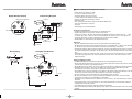
Power-Cap01 mit Remote für High-Power Endstufe
Digital Voltage Display
+
-
Status LED
Voltage display adjustment
hot
Discharging
+ Battery
Fuse
min. 40 A
Amplifier
Ground
+
-
Car Radio
Remote
min 10mm
2
/40A
Connecting Diagram
Ground
+
-
Car Radio
Remote
green
+
Charging with Remote
hot

Die durch das Ladekabel begrenzte gesamte Aufladung des Caps dauert ca. 8 Minuten. Die Digitalanzeige
und die Status LED des Power Cap beginnt erst bei ca. 9,5 Volt zu leuchten, was nach ca. 5 Minuten erreicht
ist. Die max. Aufladung auf ca. 12 bis 13,5 Volt kann über die Digitalanzeige erkannt werden, wenn diese sich
nicht mehr laufend erhöht.
Nach dem Ladeende – die Sicherung in der Plus Zuleitung für den Power Cap entfernen.
Vorsichtig die Krokodilkemmen Verbindung lösen und Ladekabel entfernen. Isoliert arbeiten, da Power Cap
jetzt vollständig geladen – Kurzschlussgefahr!
Restliche Verkabelung zur Endstufe vornehmen.
5. Schlusskontrolle:
• Korrekte Verdrahtung und Polung der Komponenten prüfen.
• Verlegung und Kontakt der Leitungen kontrollieren
• Schraubverbindungen auf Festigkeit prüfen
6. Fertig:
• Sicherung in die Plus Zuleitung wieder einsetzen.
• Power Cap übernimmt nun die Pufferung der Betriebsspannung der Endstufe.
Ausbau des Power Cap:
Starterbatterie vom Bordnetz trennen.
Kabelanschlüsse vom Power Cap entfernen
Power Cap wie unter Punkt 2 beschrieben entladen.
Achtung:
Vor dem Wiederanschließen der Starterbatterie muss sichergestellt werden, dass durch die
offenen Anschlussleitungen keine Kurzschlüsse verursacht werden können! Leitungen entsprechend
isolieren oder entfernen!
• Cool cylindrical shape, silver
• 1 Farad max. 20V direct voltage
• Integrated digital voltage indicator
• 1 status LED as charging/discharging function display
• Visual and audible reverse polarity display
• Remote connection
• Includes special charging cable with integrated 100 Ohm resistor
•Includes 2 transparent plastic holders
• E approved
• Quality select components
The Power-Cap ensures:
• Increased amplifier power with effectively up to 35% more power
•Clear improvement in sound through less distortion
• More “bass power”. Without a capacitor the on-board voltage drops 1 – 2 volts during sudden bursts of
bass. This results in distortion and loss of sound quality. The Power-Cap quickly compensates for this drop
in voltage and provides an audible solution.
• Anti-interference function for suppressing interference from on-board power supply
5
4
L
Power-Cap01 with remote for high power amplifier
Montageanleitung:
1. Starterbatterie vom Bordnetz trennen
2. Power Cap entladen:
Um eine Beschädigung oder ein unabsichtliches Entladen mit starker Hitzeentwicklung am Power Cap zu
vermeiden, muss dieser unbedingt vor dem Ein- oder Ausbauen entladen werden:
• Ringkabelschuh des Ladekabels am Pluspol des Cap mit der Inbusschraube festschrauben
• Die Krokodilklemme sicher mit dem Minuspol des Cap verbinden.
• Diesen Zustand für 5 Minuten beibehalten, erst dann ist der Cap vollständig entladen.
• Vorsicht Widerstand kann sich beim Entladen eventuell stark erwärmen – Verbrennungsgefahr!
• Danach die Krokodilklemme am Minuspol wieder lösen – andere Seite des Ladekabels vorerst am Pluspol
belassen.
3. Montage des Power Cap:
Den entladenen Power Cap mit beiliegenden Haltern sicher und in der Nähe kurz vor der Endstufe montieren.
4. Erstes Aufladen des Power Cap:
Das erste Aufladen und Aufladungen nach Komplett-Entladungen sollten über das Ladekabel erfolgen um
extrem hohe Ladeströme zu vermeiden und eine lange Lebensdauer des Power Cap zu erreichen.
a) Laden ohne Remoteanschluss:
Minuspol des Power Cap mit Massezuleitung verbinden.
Krokodilklemme mit der vorbereiteten abgesicherten Plus Zuleitung (Batterie Plus) verbinden. Hierbei
unbedingt darauf achten, dass keine anderen leitenden Teile berührt werden.
Starterbatterie wieder anklemmen.
Der Power Cap wird nun geladen, wobei der im Ladekabel integrierte Widerstand den maximalen Ladestrom
begrenzt und somit den Power Cap schützt. Vorsicht! Widerstand kann sich stark erwärmen beim Laden -
Verbrennungsgefahr! Zur Kontrolle der erreichten Ladung, kann wenn vorhanden ein Voltmeter parallel zum
Cap angeschaltet werden.
Die durch das Ladekabel begrenzte Aufladung auf 12 - 13,5 Volt dauert ca. 8 Minuten.
Nach dem Ladeende die Sicherung in der Plus Zuleitung für den Power Cap entfernen.
Vorsichtig die Krokodilkemmen Verbindung lösen und Ladekabel entfernen. Isoliert arbeiten, da Power Cap
jetzt vollständig geladen – Kurzschlussgefahr! Restliche Verkabelung zur Endstufe vornehmen.
Weiter mit Punkt 5.
b) Laden mit Remoteanschluss:
Minuspol des Power Cap mit dem Minusanschluss der Endstufe verbinden.
Massezuleitung (Zentrale Masseverbindung) mit dem Minuspol des Power Cap verbinden.
Remoteanschluss am Power Cap vornehmen.
Krokodilklemme mit der vorbereiteten abgesicherten Plus Zuleitung (Batterie Plus) verbinden. Hierbei
unbedingt darauf achten, dass keine anderen leitenden Teile berührt werden.
Starterbatterie wieder anklemmen.
Der Power Cap wird nun geladen, wobei der im Ladekabel integrierte Widerstand den maximalen Ladestrom
begrenzt und somit den Power Cap schützt. Vorsicht! Widerstand kann sich beim Laden stark
erwärmen - Verbrennungsgefahr!
Display aktivieren zur Kontrolle des Ladevorgangs: durch Anschalten z.B. des Autoradios, wenn dieses als
Remotesteuergerät fungiert!

6
7
4. Initial charging of the Power-Cap:
The initial charging and charges after completely discharging the Power-Cap must be carried out using the
charging cable to prevent extremely high charging currents and to achieve a long service life of the
Power-Cap.
a) Charging without remote connection:
Connect the minus pole of the Power-Cap to the earth line.
Connect the alligator clip to the fused plus supply line (battery plus). Ensure that no other conductive parts
are touched.
Reconnect the starter battery.
The Power-Cap is now charged, whereas the resistor integrated into the charging cable limits the maximum
charging current and thus protects the Power-Cap. Caution! The resistor may heat up excessively when
charging - risks of burns! If available, a voltage meter can be connected to the Power-Cap to control the
charge reached.
The charging cable limits the charge to 12 - 13.5 volt and lasts approximately 8 minutes.
Once the charging procedure is complete remove the fuse in the plus supply line for the Power-Cap.
Carefully loosen the alligator clip connection and remove the charging cable. Ensure proper insulation when
working, since the Power-Cap is now fully charged – danger of short circuit!
Carry out the remaining wiring to the amplifier.
Continue with point 5.
b) Charging with remote connection:
Connect the minus pole of the Power-Cap to the minus pole of the amplifier.
Connect the earth line (central earth terminal) to the minus pole of the Power-Cap.
Carry out the remote connection at the Power-Cap.
Connect the alligator clip to the fused plus supply line (battery plus). Ensure that no other conductive parts
are touched.
Reconnect the starter battery.
The Power-Cap is now charged, whereas the resistor integrated into the charging cable limits the maximum
charging current and thus protects the Power-Cap. Caution! The resistor may heat up excessively when
charging - risks of burns!
Activate the display to control the charging procedure: by switching on for example, the car radio, if this
functions as a remote control device!
The charging cable limits the entire charging of the Power-Cap and lasts approximately 8 minutes. The
digital display and the LED status of the Power-Cap are first illuminated at approximately 9.5 volt which is
reached in approximately 5 minutes. The maximum charge of approximately 12 to 13.5 volt can be detected
via the digital display, if it does not continually increase.
Once the charging procedure is complete – remove the fuse in the plus supply line for the Power-Cap.
Carefully loosen the alligator clip connection and remove the charging cable. Ensure proper insulation when
working, since the Power-Cap is now fully charged – danger of short circuit!
Carry out the remaining wiring to the amplifier.
5. Final check:
• Check that the components are wired correctly and that the polarity is correct.
• Check that the supply lines are routed correctly.
• Ensure that the screw connections are tight
Functions:
• The charging/discharging function is indicated the illuminated green LED
• The digital display shows the current on-board voltage. Display range approximately 9.5 to 19.5 V. Nothing
below this range is displayed. Above this range the display remains unchanged!
• The setting control (voltage display adjustment) adjusts the digital display. The control is preset, sealed
and cannot be accessed directly. The transparent cover of the Power-Cap must be removed for adjusting.
• Reverse polarity of the Power-Cap is indicated by a loud audible signal and then by the illuminated red
status LED. Immediately disconnect the Power-Cap from the on-board power supply, as there is a risk of
explosion or irreparable damage!
Attention: The following must be observed!
• Disconnect the starter battery before beginning installation, so it is no longer connected to the on-board
power supply
• The plus and minus poles of the Power-Cap may not be reversed or short-circuited! Otherwise there is a
risk of explosion or irreparable damage!
• During installation, ensure that no other parts of the vehicle are damaged or interfered with!
• Choose the installation location so that it cannot interfere with moving parts or cause danger when driving.
• Shorter cables routes to the amplifier optimise its effect. When using several amplifiers mount the Power
Cap close to the most powerful. Cable lengths less than 30cm to the amplifier are ideal.
• Cut the connection lines to length accordingly and equip them with terminals.
• The connection lines must have sufficient cross sections and be fused in accordance with regulations and
routed correctly to prevent cables fires!
• The resistor in the charging cable can become excessively warm during operation – caution when
touching, risks of burns!
• Buffer capacitors must be clamped or discharged when working on the vehicle’s electronics or before
taking it to a repair shop.
• The capacitor must have a capacity of 0.1 F per 100 watt of power.
• The capacitor cannot correct insufficient wiring or noise suppression of the vehicle.
Assembly instructions:
1. Disconnect the starter battery from the on-board power supply
2. Discharge the Power-Cap:
In order to avoid damage or an unintentional discharging with dangerous heat development at the
Power-Cap, it must be discharged as follows before installing or removing:
• Connect the ring terminal of the charging cable to the plus pole of the Power-Cap using the Allen key.
• Connect the alligator clip securely to the minus pole of the Power-Cap.
• Leave for 5 minutes – the Power-Cap is not fully discharged until then.
• Caution the resistor may heat up excessively when discharging - risks of burns!
• Afterwards, loosen the alligator clip at the minus pole – leave the charging cable on the plus pole for the
time being.
3. Installing the Power-Cap:
Attach the discharged Power-Cap securely and tightly near the amplifier using the holders provided.

6. Finished:
• Replace the fuse in the plus supply line.
• Power-Cap now takes over the buffering of the amplifier’s operating voltage.
Removing the Power-Cap:
Disconnect the starter battery from the on-board power supply.
Remove the cable connections from the Power-Cap
Discharge the Power-Cap as described in point 2.
Attention: Before you connect the starter battery again, you must ensure that the open connection lines
cannot cause short circuits! Insulate the lines accordingly or remove them!
• Construction cylindrique, attractive, argentée
• 1 farad, tension continue maxi. 20V
• Affichage numérique de la tension intégré
• 1 DEL d’état, affichage de la fonction de charge/décharge
• Affichage visuel et acoustique en cas d’inversion de la polarité
• Connexion télécommande
• Câble spécial de charge à résistance intégrée de 100 ohm
• 2 supports en plastique transparent
• Certification électrique
• Composants haut de gamme
Power Cap permet:
• De meilleures perfomances d’amplification, en augmentation de jusqu’à 35%
• Amélioration significative du son grâce à la réduction des distorsions
• Basses plus puissantes. Lors de l’attaque des basses, la tension à bord chute de 1-2 volts sans
condensateur. Ce qui provoque des distorsions et une réduction de la tonalité. Power Cap est en mesure
de compenser immédiatement cette chute de tension et procure ainsi une aide audible.
• Fonction antiparasite pour supprimer les perturbations du circuit de bord
Fonctions:
• La fonction de charge/décharge est affichée par la DEL verte d’état
• L’affichage numérique indique la tension actuelle à bord. Plage d’affichage entre 9,5 et 19,5V. Pas
d’affichage des valeurs inférieures. L’ affichage reste inchangé avec des valeurs supérieures!
• Le régulateur (voltage display adjustment) sert à régler l’affichage numérique. Il est pré-réglé, scellé et
non accessible directement. Un réglage est possible uniquement après avoir déposé le cache transparent
de la tête.
• Une inversion de la polarité de la tête d’amplification est indiquée par un signal acoustique bruyant et de
la DEL d’état allumée en rouge! Séparer immédiatement la tête du circuit de bord, car il existe des risques
de destruction ou d’explosion!
8
9
Attention: à respecter impérativement!
• Débrancher la batterie de démarrage du circuit de bord avant de commencer l’installation!
• Les pôle positif et négatif de la tête d’amplification ne doivent ni être court-circuités ni présenter une
inversion de polarité ! Il existe sinon des risques d'explosion ou de destruction !
• Lors de l’installation, veillez à n’endommager aucune partie du véhicule !
• Sélectionnez le lieu d’installation de sorte que la tête d’amplification ne gêne ni ne mette en danger les
occupants lors de la conduite.
• Une longueur réduite de câblage jusqu’à l’amplificateur de puissance en optimisent les performances.
Avec plusieurs amplificateurs de puissance, installez Power Cap à proximité du plus puissant. Une lon-
gueur de câble inférieure à 30 cm est idéale.
• Raccourcissez les câbles de raccordement en conséquence et équipez-les de cosses.
• Les câbles électriques doivent présenter une section suffisante, être protégés conformément aux normes
et installés de façon conforme afin d’éviter qu’ils ne brûlent.
• La résistance du câble de charge peut subir un fort échauffement – Attention, risaque de brûlure en cas
de contact.
• Lors de travaux sur le circuit électrique du véhicule ou avant une visite à l’atelier, déconnectez ou
déchargez les condensateurs tampon.
• Une capcité decondensateur de 0,1 kW est requise par 100 W de puissance.
• Un câblage ou un blindage insuffisant d uvéhicule ne peut être rectifié par le condensateur.
Instructions de montage:
1. Débranchez la batterie de démarrage du circuit de bord
2. Décharge de la tête d’amplification:
La tête d’amplification doit impérativement être déchargée avant d’être installée ou démontée pour éviter
une décharge accidentelle dégageant une forte chaleur ou toute autre détérioration.
• Vissez à fond la cosse ronde du câble de charge au pôle positif de la tête d’amplification, avec la vis à six
pans creux
• Connectez solidement la pince croco au pôle négatif de la tête d’amplification.
• Conservez ce branchement pendant 5 minutes, nécessaires à la décharge complète de la tête d’amplificati-
on.
• Attention, la résistance peut s’échauffer fortement pendant la décharge – risque de brûlure !
• Séparez ensuite la pince croco du pôle négatif – l’autre extrémité du câble demeurant connecté au pôle
positif.
3. Installation de la tête d’amplification:
Installez la Power Cap déchargée solidement sur les supprots fournis juste avant l’amplificateur de
puissance.
4. Première recharge de la Power Cap:
La première recharge et les recharges consécutives à des décharges complètes doivent se faire via le câble
de charge, ce qui évite les courants de charge extrêmement élevés et améliore la durée de vie de la tête
d’amplification.
a) Charge sans connexion télé:
Connectez le pôle négatif de la tête d’amplification à l’alimentation de masse.
Connectez la pince croco avec l’alimentation positive (plus de batterie) protégée préparée. Veillez
impérativement à ne toucher aucune autre pièce.
¬
Power Cap01 à mode télé pour amplificateurs de puissance hautes performances

10
Connectez à nouveau la batterie de démarrage.
La charge de Power Cap a lieu, et la résistance intégrée au câble de charge limite le courant maximum de
charge, ce qui protège la Power Cap. Attention ! La résistance peut s’échauffer fortement pendant la charge
– risque de brûlure! Pour contrôler la charge atteinte, vous pouvez brancher un voltmètre parallèlement à la
tête d’amplification.
La recharge limitée par le câble de charge à 12-13,5 volt dure environ 8 minutes.
Une fois la charge achevée déposer le fusible situé dans l’alimentation positive et destiné à la Power Cap.
Défaites avec précaution la connexion de la prise croco et enlevez le câble de charge. Travaillez protégé,
car la tête d’amplification est chargée à fond – risque de court-circuit!
Effectuez le reste du câblage vers l’amplificateur de puissance. Poursuivez par le Point 5.
b) Charge avec connexion télé:
Connectez le pôle négatif de Power Cap au raccord négatif de l’amplificateur de puissance.
Connectez le pôle négatif de la tête d’amplification à l’alimentation de masse (connexion masse centrale).
Etablissez la connexion télé sur la tête d’amplification.
Connectez la pince croco avec l’alimentation positive (plus de batterie) protégée préparée. Veillez
impérativement à ne toucher aucune autre pièce.
Connectez à nouveau la batterie de démarrage.
La charge de Power Cap a lieu, et la résistance intégrée au câble de charge limite le courant maximum de
charge, ce qui protège la Power Cap. Attention ! La résistance peut s’échauffer fortement pendant la charge
– risque de brûlure!
Activez l’affichage pour contrôler le déroulement de la charge : en allumant l’autoradio, par exemple, si
celui-ci fait office de télécommande!
La recharge totale limitée par le câble de charge à 12-13,5 volt dure environ 8 minutes. L’ affichage
numérique et la DEL d’état s’allument à partir d’une valeur de 9,5 volt, atteinte après environ 5 minutes de
charge. La recharge maximum d’environ 12 à 13,5 volt peut être détectée par l’affichage numérique
lorsqu’elle présente une certaine stabilité.
Une fois la charge achevée – déposez le fusible situé dans l’alimentation positive et destiné à la Power Cap.
Défaites avec précaution la connexion de la prise croco et enlevez le câble de charge. Travaillez protégé,
car la tête d’amplification est chargée à fond – risque de court-circuit!
Effectuez le reste du câblage vers l’amplificateur de puissance.
5. Contrôle terminal:
• Contrôlez le câblage et la polarité des composants.
• Contrôlez la pose et les contacts des câbles.
• Contrôlez le bon serrage des raccords.
6. Tout est prêt:
• Remettez en place le fusible de l’alimentation positive.
• Power Cap est alors chargée de buffériser la tension de service de l’amplificateur de puissance.
Démontage de la tête d’amplification:
Débranchez la batterie de démarrage du circuit de bord.
Défaites les connexions câblées de la tête d’amplification.
Déchargez la tête d’amplification en suivant les explications du point 2.
Attention: avant de rebrancher la batterie de démarrage, contrôlez qu’aucun court-circuit ne peut être
provoqué par des câbles non protégés! Isolez les câbles de façon conforme ou retirez-les!
-
 1
1
-
 2
2
-
 3
3
-
 4
4
-
 5
5
-
 6
6


in anderen Sprachen
- English: Hama 00062403 Owner's manual
- français: Hama 00062403 Le manuel du propriétaire