LD Systems CURV 500 ES Portable Column PA System 2400W Benutzerhandbuch
- Typ
- Benutzerhandbuch

USER´S MANUAL
BEDIENUNGSANLEITUNG
MANUEL D`UTILISATION
MANUAL DE USUARIO
INSTRUKCJA OBSŁUGI
MANUALE D‘ USO
操作说明书
操作說明書
CURV 500
®
PORTABLE ARRAY SYSTEM WITH 4-CHANNEL MIXER
LDCURV500 SERIES

CONTENTS / INHALTSVERZEICHNIS / CONTENU / CONTENIDO / TREŚĆ / CONTENUTO / 内容
/ 內容
ENGLISH
PREVENTIVE MEASURES 3-4
INTRODUCTION 4
SETUP 5
CONNECTIONS, CONTROLS AND INDICATORS 6-11
LD CURV 500
®
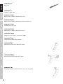
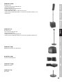
SETS, EXPANSIONS AND ACCESSORIES 12-14
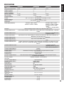
SPECIFICATIONS 15
MANUFACTURER´S DECLARATIONS 16
CONFIGURATION EXAMPLES 115-116
DEUTSCH
SICHERHEITSHINWEISE 17-18
EINFÜHRUNG 18-19
AUFBAU 19
ANSCHLÜSSE, BEDIEN- UND ANZEIGEELEMENTE 20-25
LD CURV 500
®
SETS, ERWEITERUNGEN UND ZUBEHÖR 26-28
TECHNISCHE DATEN 29-30
HERSTELLERERKLÄRUNGEN 30
KONFIGURATIONSBEISPIELE 115-116
FRANCAIS
MESURES PRÉVENTIVES 31-32
INTRODUCTION 32-33
MONTAGE 33
CONNECTEURS, CONTRÔLES ET INDICATEURS 34-39
LD CURV 500
®
SETS, EXPANSIONS AND ACCESSORIES 40-42
CARACTÉRISTIQUES 43-44
DECLARATIONS 44
EXEMPLES DE CONFIGURATION 115-116
ESPAÑOL
MEDIDAS DE SEGURIDAD 45-46
INTRODUCCIÓN 46
MONTAJE 47
CONEXIONES, CONTROLES E INDICADORES 48-53
LD CURV 500
®
SETS, EXPANSIONS AND ACCESSORIES 54-56
CARACTERÍSTICAS TÉCNICAS 57-58
DECLARACIÓN DEL FABRICANTE 58
EJEMPLOS DE CONFIGURACIÓN 115-116
POLSKI
ŚRODKI OSTROŻNOŚCI 59-60
WPROWADZENIE 60-61
BUDOWA 61
PRZYŁĄCZA, ELEMENTY OBSŁUGI I WYŚWIETLACZA 62-67
ZESTAWY LD CURV 500
®
, ROZSZERZENIA I 68-70
SPECYFIKACJE 71-72
DEKLARACJE PRODUCENTA 72
PRZYKŁADY KONFIGURACJI 115-116
ITALIANO
MISURE PRECAUZIONALI 73-74
INTRODUZIONE 74
INSTALLAZIONE 75
CONNESSIONI, COMANDO E VISUALIZZAZIONE 76-81
MODELLI, ESTENSIONI E ACCESSORI LD CURV 500
®
81-84
SPECIFICHE 85-86
DICHIARAZIONI DEL PRODUTTORE 86
ESEMPI DI CONFIGURAZIONE 115-116
安全提示 87-88
引言 88
安装 89
连接器、操作显示元件 90-95
LD CURV 500
®
套件、扩展部分和配件 96-98
技术数据 99-100
制造商声明 100
设置示例 115-116
安全提示 101-102
引言 102
安裝 103
連接器、操作顯示元件 104-109
LD CURV 500
®
套件、擴展部分和配件 109-112
技術資料 113-114
製造商聲明 114
設定範例 115-116

3
DEUTSCHENGLISH FRANCAIS
ESPAÑOL
POLSKI ITALIANO
•••
ENGLISH
You‘ve made the right choice!
We have designed this product to operate reliably over many years. LD Systems stands for this with its name and many years of experience
as a manufacturer of high-quality audio products. Please read this User‘s Manual carefully, so that you can begin making optimum use of
your LD Systems product quickly.
You can find more information about LD-SYSTEMS at our Internet site WWW.LD-SYSTEMS.COM
PREVENTIVE MEASURES
1. Please read these instructions carefully.
2. Keep all information and instructions in a safe place.
3. Follow the instructions.
4. Observe all safety warnings. Never remove safety warnings or other information from the equipment.
5. Use the equipment only in the intended manner and for the intended purpose.
6. Use only sufficiently stable and compatible stands and/or mounts (for fixed installations). Make certain that wall mounts are properly installed and
secured. Make certain that the equipment is installed securely and cannot fall down.
7. During installation, observ e the applicable safety regulations for your country.
8. Never install and operate the equipment near radiators, heat registers, ovens or other sources of heat. Make certain that the equipment is always
installed so that is cooled sufficiently and cannot overheat.
9. Never place sources of ignition, e.g., burning candles, on the equipment.
10. Ventilation slits must not be blocked.
11. Do not use this equipment in the immediate vicinity of water (does not apply to special outdoor equipment - in this case, observe the
special instructions noted below. Do not expose this equipment to flammable materials, fluids or gases. Avoid direct sunlight!
12. Make certain that dripping or splashed water cannot enter the equipment. Do not place containers filled with liquids, such as vases or
drinking vessels, on the equipment.
13. Make certain that objects cannot fall into the device.
14. Use this equipment only with the accessories recommended and intended by the manufacturer.
15. Do not open or modify this equipment.
16. After connecting the equipment, check all cables in order to prevent damage or accidents, e.g., due to tripping hazards.
17. During transport, make certain that the equipment cannot fall down and possibly cause property damage and personal injuries.
18. If your equipment is no longer functioning properly, if fluids or objects have gotten inside the equipment or if it has been damaged in anot
her way, switch it off immediately and unplug it from the mains outlet (if it is a powered device). This equipment may only be repaired by
authorized, qualified personnel.
19. Clean the equipment using a dry cloth.
20. Comply with all applicable disposal laws in your country. During disposal of packaging, please separate plastic and paper/cardboard.
21. Plastic bags must be kept out of reach of children.
FOR EQUIPMENT THAT CONNECTS TO THE POWER MAINS
22. CAUTION: If the power cord of the device is equipped with an earthing contact, then it must be connected to an outlet with a protective
ground. Never deactivate the protective ground of a power cord.
23. If the equipment has been exposed to strong fluctuations in temperature (for example, after transport), do not switch it on immediately.
Moisture and condensation could damage the equipment. Do not switch on the equipment until it has reached room temperature.
24. Before connecting the equipment to the power outlet, first verify that the mains voltage and frequency match the values specified on the
equipment. If the equipment has a voltage selection switch, connect the equipment to the power outlet only if the equipment values and the
mains power values match. If the included power cord or power adapter does not fit in your wall outlet, contact your electrician.
25. Do not step on the power cord. Make certain that the power cable does not become kinked, especially at the mains outlet and/or power
adapter and the equipment connector.
26. When connecting the equipment, make certain that the power cord or power adapter is always freely accessible. Always disconnect the
equipment from the power supply if the equipment is not in use or if you want to clean the equipment. Always unplug the power cord and
power adapter from the power outlet at the plug or adapter and not by pulling on the cord. Never touch the power cord and power adapter
with wet hands.
27. Whenever possible, avoid switching the equipment on and off in quick succession because otherwise this can shorten the useful life of
the equipment.
28. IMPORTANT INFORMATION: Replace fuses only with fuses of the same type and rating. If a fuse blows repeatedly, please contact an
authorised service centre.
29. To disconnect the equipment from the power mains completely, unplug the power cord or power adapter from the power outlet.
30. If your device is equipped with a Volex power connector, the mating Volex equipment connector must be unlocked before it can be removed.
However, this also means that the equipment can slide and fall down if the power cable is pulled, which can lead to personal injuries and/or
other damage. For this reason, always be careful when laying cables.
31. Unplug the power cord and power adapter from the power outlet if there is a risk of a lightning strike or before extended periods of disuse.
CAUTION
RISK OF ELECTRIC SHOCK
DO NOT OPEN
CAUTION: Never remove the cover, because otherwise there may be a risk of electric shock.
There are no user serviceable parts inside. Have repairs carried out only by qualified service
personnel.

4
DEUTSCH
ENGLISH
FRANCAIS
ESPAÑOLPOLSKI
ITALIANO
•••
The lightning flash with arrowhead symbol within an equilateral triangle is intended to alert the user to the presence of
uninsulated “dangerous voltage” within the product’s enclosure that may be of sufficient magnitude to constitute a risk of
electrical shock.
The exclamation mark within an equilateral triangle is intended to alert the user to the presence of important operating and
maintenance instructions.
CAUTION – HIGH VOLUME LEVELS WITH AUDIO PRODUCTS!
This equipment is intended for professional use. Therefore, commercial use of this equipment is subject to the respectively applicable national
accident prevention rules and regulations. As a manufacturer, Adam Hall is obligated to notify you formally about the existence of potential
health risks.
Hearing damage due to high volume and prolonged exposure: When in use, this product is capable of producing high sound-pressure levels
(SPL) that can lead to irreversible hearing damage in performers, employees, and audience members.
For this reason, avoid prolonged exposure to volumes in excess of 90 dB.
To prevent possible hearing damage, avoid listening at high volume levels over long periods of time.
Even exposure to short bursts of loud noise can result in hearing loss. Please keep the volume constantly at a comfortable level.
* CURV500S, CURV500SE can be used in following electromagnetic environment: residential, commercial and light industrial, urban
outdoors. They are the apparatus not intended for rack mounting.
* The peak inrush currents equal to 8.86 A.
*This device complies with part 15 of the FCC Rules. Operation is subject to the following two conditions: (1)this device may not cause
harmful interference ,and (2)this device must accept any interference received, including interference that may cause undesired operation.
Changes or modifications not expressly approved by the party responsible for compliance could void the user’s authority to operate the equipment.
NOTE: This equipment has been tested and found to comply with the limits for a Class B digital device, pursuant to Part 15 of the FCC
Rules. These limits are designed to provide reasonable protection against harmful interference in a residential installation. This equipment
generates, uses and can radiate radio frequency energy and, if not installed and used in accordance with the instructions, may cause
harmful interference to radio communications. However, there is no guarantee that interference will not occur in a particular installation. If
this equipment does cause harmful interference to radio or television reception, which can be determined by turning the equipment off and
on, the user is encouraged to try to correct the interference by one or more of the following measures:
- Reorient or relocate the receiving antenna.
- Increase the separation between the equipment and receiver.
- Connect the equipment into an outlet on a circuit different from that to which the receiver is connected.
- Consult the dealer or an experienced radio/TV technician for help.
INTRODUCTION
The compact, transport-friendly CURV 500
®
is an easily configurable array system with a maximum of 4 satellites, latching into each other,
which are operated via a SmartLink
®
adapter. The elements, only 12 x 12 cm in size, are equipped with LD System’s own WaveAhead
®
technology, a 4” and three 1” drivers provide a coherent and extremely detailed playback with high pressure and dynamics.
The 10” bass-reflex subwoofer also houses the DSP controlled Class-D power amplifier of the CURV 500
®
including a limiter, protection
against short circuit, overheating, over-voltage, as well as a 4-channel mixer with 16 digital effect presets and Bluetooth
®
. Combo, and
Speakon-compatible sockets offer extensive connectivity options, and the subwoofer features 4 digital system presets, an M20 threaded
flange and 3 ergonomic carrying handles. Available in 3 sets for mobile and fixed use, the convenient overall solution CURV 500
®
boasts a
low weight and a wide, far-reaching sound dispersion.
General information
Before start-up, the subwoofer of the LD Systems CURV 500
®
array system must be placed upright on its rubber feet, on a flat surface.
Never operate your system on a trolley, as there is a risk that the entire system might be unstable. Accidents and damage may result. To
ensure adequate cooling, during operation a minimum distance of 50 cm must be maintained between the back of the subwoofer and other
objects such as walls for example. Please ensure the correct connection of audio and power connections for the system and all connected
devices such as mixers, CD players, etc. Use only undamaged cables of suitable diameter and always unwind cable reels completely. If
necessary, use cable bridges to avoid tripping over loose cables. Never place the device directly on an edge. Do not place the subwoofer on
a table. To avoid unwanted background noise when turning on connected devices, always turn on the system last and turn it off first.

5
DEUTSCHENGLISH FRANCAIS
ESPAÑOL
POLSKI ITALIANO
•••
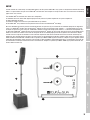
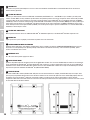
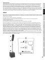
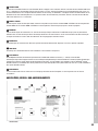
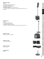
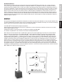
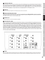
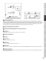
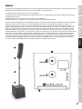
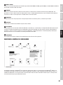
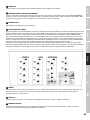
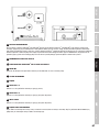
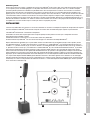
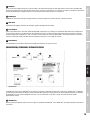
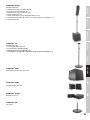
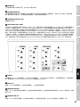
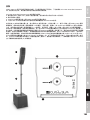
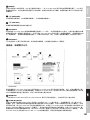
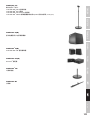
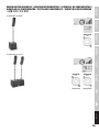
SETUP
In order to allow for a wide variety of configuration options, the LD Systems CURV 500
®
array system is designed to be modular. Described
below is a representative setup of the LD CURV 500
®
ES Entertainer Set. Examples of setups for other Sets can be found on the following
pages of this user’s manual.
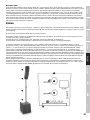
The LD CURV 500
®
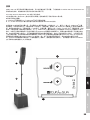
ES Entertainer Set consists of 4 components:
A. subwoofer with mixer, built-in DSP (digital signal processor) and class-D power amplifier for the system components.
B. height adjustable spacer bar.
C. SmartLink
®
adapter as the base for up to 4 CURV 500
®
array satellites.
D. Four CURV 500
®
array satellites with the patented click mechanism and WaveAhead
®
technology.
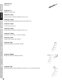
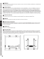
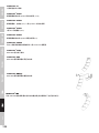
Once the subwoofer (A) has been placed in the desired location, the spacer bar (B) is screwed into the subwoofer (flange on the top). When
using 1 or 2 CURV 500
®
satellites, plug the SmartLink
®
adapter (C) using the rear flange (mark satellite 1 + 2, upright position, fig. E) onto
the top of the spacer bar; when using 3 or 4 CURV 500
®
satellites using the front flange (mark satellite 3 + 4, forward inclined position, fig.
F). Now slide a CURV 500
®
satellite (D) from the rear onto the SmartLink
®
adapter (C) until it stops, while pressing the spring-loaded release
button on the side of the satellite. Ensure that the two guide rails of the satellite properly slide into the grooves of the SmartLink
®
adapter
in order to ensure a tight fit and establish a contact for both components. Now release the button to lock the connection and to bring the
button back to its original position. Proceed in the same manner as described above to add other satellites. Now connect the speaker output
SATELLITE OUT of the CURV 500
®
subwoofer with the speaker input INPUT SIGNAL (G) of the SmartLink
®
adapter using the supplied speaker
cable. When disassembling, please proceed in reverse order. For fixed installations and desktop applications, a terminal block connector (fig.
H, terminal block included) is located on the back of the SmartLink
®
adapter. The speaker input INPUT SIGNAL (G) is parallel wired with the
terminal block connector (H).
D
C
B
A
G
C
F
E
H

6
DEUTSCH
ENGLISH
FRANCAIS
ESPAÑOLPOLSKI
ITALIANO
•••
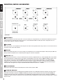
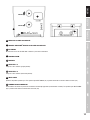
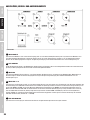
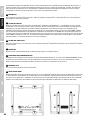
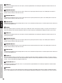
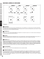
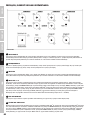
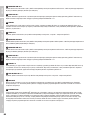
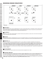
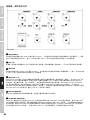
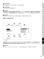
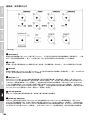
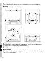
CONNECTIONS, CONTROLS AND INDICATORS
1 3 4 4
5 6
7
2
8 9 10 10
LDCURV500S
1
INPUT MIC/HI-Z
Balanced microphone or instrument input (XLR / 6.3 mm jack combo). It is also possible to use an unbalanced microphone or instrument
cable (mono jack). Pay attention to the setting of switch 2, as described below. NOTE: The XLR input socket is designed for the 12 V
phantom power supply of a condenser microphone.
2
HI-Z SWITCH
When using channel 1 as a microphone channel, bring the HI-Z switch to the up position. When using channel 1 as an instrument channel,
bring the HI-Z switch to the down position.
3
INPUT MIC
Balanced microphone input (XLR / 6.3 mm jack combo) It is also possible to use an unbalanced microphone cable (mono jack). NOTE: The
XLR input socket is designed for the 12 V phantom power supply of a condenser microphone.
4
INPUT LINE 3 + 4
Balanced line inputs with XLR / 6.3 mm jack combo sockets for connecting a playback device (e.g. mixer, keyboard). When using a CURV
500
®
ES Entertainer Set as a Mono Set (the array satellites mounted together on the spacer bar), the MONO / STEREO (26) switch on the
mixer control panel must be pressed down (MONO). An incoming audio signal will be mono summed. When using a CURV 500
®
ES
Entertainer Set as a Stereo Set (2 array satellites mounted left and right), or using the CURV 500
®
PS Power Set (Stereo), the MONO /
STEREO (26) switch on the mixer control panel must not be pressed down (STEREO). An incoming stereo audio signal will be output in
stereo. The latter also applies when using the LD CURV 500
®
AVS Stereo A/V Set (switch 26 -> STEREO).
5
LINE OUT MONO MIX
Balanced line output with male XLR socket. Output of the mixer summing signal in Mono.
6
SYSTEM OUT CURV 500 SE
Male 5-pin XLR socket to connect the CURV 500
®
SE Subwoofer expansion, or the CURV 500
®
PES Power expansion sets. When using a
CURV 500
®
SE Subwoofer expansion, the MONO / STEREO (26) switch on the mixer control panel must be pressed down (MONO). An
incoming audio signal will be mono summed. When using a CURV 500
®
PES Power Expansion Set to create a Stereo Set, the MONO /
STEREO (26) switch on the mixer control panel must not be pressed down (STEREO). An incoming stereo signal on INPUT LINE 3 / 4 will be
output in stereo.

7
DEUTSCHENGLISH FRANCAIS
ESPAÑOL
POLSKI ITALIANO
•••
7
POWER LED
Lights up once the system is properly connected to the power mains and switched on.
8
POWER CONNECTOR WITH FUSE HOLDER
IEC power socket with built-in fuse holder. An appropriate power cord is included in the delivery. IMPORTANT INFORMATION: Replace the
fuse only with a fuse corresponding to the operating voltage. Please observe the label on the housing. If the fuse blows repeatedly, please
contact an authorised service centre.
9
POWER ON / OFF
On / Off switch for the power supply of the device.
10
SATELLITE OUT LEFT / RIGHT
Speakon compatible outputs for controlling the LD CURV 500
®
satellites. Up to four LD CURV 500® satellites can be operated at each of the
outputs simultaneously (e.g. for voice and sound). When using a CURV 500
®
ES Entertainer Set as a Mono Set, use the satellite output LEFT
for the control of the LD CURV 500 satellites and the MONO / STEREO (26) on the mixer control panel switch must be pressed down (MONO).
When using a LD CURV 500
®
ES Entertainer Set as a Stereo Set (2 array satellites mounted left and right), or when using the LD CURV 500
®
AVS A/V Set, use both satellite outputs LEFT and RIGHT to control the LD CURV 500
®
satellites left and right and the MONO / STEREO (26)
switch on the mixer control panel must not be pressed down (STEREO). An incoming stereo audio signal will be output in stereo. The use of
the LD CURV 500
®
PS Power Set as a Stereo Set (or the combination of LD CURV 500
®
ES and LD CURV 500
®
PES) requires the use of the
satellite output LEFT (left) for the control of the LD CURV 500
®
satellite on the left. The LD CURV 500
®
satellite on the right is controlled by
the satellite output of the expansion subwoofer SATELLITE OUT RIGHT.
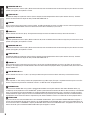
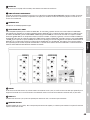
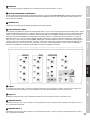
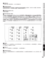
12
13
14
15
11
17
18
19
20
16
21
22
23
24
25
26
27
28
29
30
31
11
LED CH 1
When a signal is present at the input of channel 1 (CH 1), the LED indicator lights up green; if the LED is red, the channel is operating at the
clipping range. To avoid distortion, reduce the volume level of the volume controller (12) of channel 1.
12
LEVEL CH 1
Volume controller for channel 1 (CH 1). Turning the dial to the right increases the volume and turning it to the left decreases it.
13
EQUALIZER HIGH CH 1
Equalizer high band for channel 1 (CH 1). When turned to the left, levels are lowered, when turned to the right, they are raised. In the centre
position (resting point), the equalizer is inactive.

8
DEUTSCH
ENGLISH
FRANCAIS
ESPAÑOLPOLSKI
ITALIANO
•••
14
EQUALIZER LOW CH 1
Equalizer bass band for channel 1 (CH 1). When turned to the left, levels are lowered, when turned to the right, they are raised. In the centre
position (resting point), the equalizer is inactive.
15
LEVEL DFX CH 1
Controller for adding the signal from channel 1 (Effects Send) to the internal digital effects device (effect volume channel 1). The effect
presets are selected with the help of the rotary encoder DFX PRESETS Nº 31.
16
LED CH 2
When a signal is present at the input of channel 2 (CH 2), the LED indicator lights up green; if the LED is red, the channel is operating in the
clipping range. To avoid distortion, reduce the volume level of the volume controller (17) of channel 2.
17
LEVEL CH 2
Volume controller for channel 2 (CH 2). Turning the dial to the right increases the volume and turning it to the left decreases it.
18
EQUALIZER HIGH CH 2
Equalizer high band for channel 2 (CH 2). When turned to the left, levels are lowered, when turned to the right, they are raised. In the centre
position (resting point), the equalizer is inactive.
19
EQUALIZER LOW CH 2
Equalizer bass band for channel 2 (CH 2). When turned to the left, levels are lowered, when turned to the right, they are raised. In the centre
position (resting point), the equalizer is inactive.
20
LEVEL DFX CH 2
Controller for adding the signal from channel 2 (Effects Send) to the internal digital effects device (effect volume channel 2). The effect
presets are selected with the help of the rotary encoder DFX PRESETS Nº 31.
21
LED CH 3 / 4
When an audio signal is present at the input of channel 3 /4 (CH 3/4), the LED indicator lights up green; if the LED is red, the channel is
operating in the clipping range. To avoid distortion, reduce the volume level of the playback device (e.g. keyboard, mixer) or the level of the
volume controller 22.
22
LINE IN LEVEL CH 3 / 4
Volume controller for channel 3 / 4 (CH 3 / 4). Turning the dial to the right increases the volume and turning it to the left decreases it.
23
AUX INPUT
Stereo input with 3.5 mm stereo jack socket for a playback device (e.g. MP3 Player). The input is in parallel to the line inputs 3 and 4. The
volume is adjusted using the volume controller of channel 3 / 4 LEVEL CH 3/4 on the playback device.
24
BLUETOOTH LED
The mixer of the LD CURV 500
®
array system is equipped with Bluetooth, meaning that audio files from another Bluetooth device (e.g.
smartphone) can be played back on the LD CURV 500
®
speakers (maximum distance between two devices about 10 metres). If no Bluetooth
device is connected with the internal Bluetooth unit, the blue Bluetooth LED flashes briefly twice every 3 seconds or so, while the pairing
standby LED flashes approx. every 0.5 second; if the Bluetooth LED is on permanently, then a Bluetooth connection is established and the
track playback can be started. The volume is adjusted using the volume controller of channel 3 / 4 LEVEL CH 3/4 on the playback device.
25
HOLD TO LINK
To pair and connect the internal Bluetooth device with a Bluetooth-enabled device, press and hold the HOLD to LINK button for approx. 3
seconds until the Bluetooth LED (24) flashes (approx. 2 Hz), enable Bluetooth on your Bluetooth device and search for available devices on
the user interface. Select “LD CURV500
®
” and pair your Bluetooth device with the internal Bluetooth device. The playback can now start. To
end the connection, press and hold the HOLD to LINK button again for approx. 3 seconds.

9
DEUTSCHENGLISH FRANCAIS
ESPAÑOL
POLSKI ITALIANO
•••
26
MONO / STEREO
To have a Mono summed output signal on the mixer, the MONO / STEREO (26) switch on the mixer control panel must be pressed down in
the MONO position. If the MONO / STEREO switch is not pressed down, the output signal is in stereo.
27
MAIN LED
If an audio signal is present on the sum channel, the LED lights up green. As soon as the LD CURV 500
®
array system is operated in the
clipping range, the LED turns red. Brief flashing is not a cause for concern, since the internal audio limiter compensates for over-modulation.
Permanent illumination should be avoided by reducing the input level.
28
MAIN LEVEL
Volume control for the summing channel. When turned to the left, overall volume levels are lowered, when turned to the right, they are raised.
29
SUB LEVEL
Adjusting the volume ratio of the subwoofer to the satellite speakers.
30
DSP PRESETS
Since it is possible to vary the number of connected LD CURV 500
®
satellites (1 - 4 units), the DSP settings must be adjusted accordingly,
to achieve a homogeneous sound distribution for all four variations (equalizer settings and adjusting the bass level). Set the rotary encoder
on number 1 if you only want to operate one satellite in the LD CURV 500
®
system (1 unit for mono or 1 unit each left and right for stereo).
Proceed in the same way, if you want to operate 2, 3, or 4 satellites in the system.
31
DFX PRESETS
16 different effects presets are available to you. Use the rotary encoder to select one of the presets as desired.
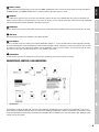
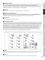
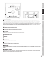
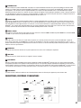
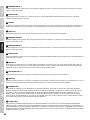
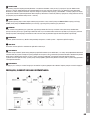
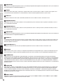
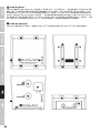
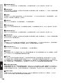
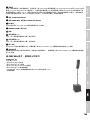
CONNECTIONS, CONTROLS AND INDICATORS
32
33
34
35
36 37 38
LDCURV500SE
The Subwoofer expansion LD CURV 500
®
SE, when used individually, complements the bass output of the LD CURV 500
®
array system.
Furthermore, the subwoofer expansion allows the connection of additional LD CURV 500
®
satellites. The intelligent signal control is carried
out by the DSP (digital signal processor) integrated into the LD CURV 500
®
S Subwoofer via the 5-pin XLR system cable, additional system
settings are thus not required.

10
DEUTSCH
ENGLISH
FRANCAIS
ESPAÑOLPOLSKI
ITALIANO
•••
32
GROUND LIFT
This feature can prevent ground loops that can occur when the subwoofers LD CURV 500
®
S and LD CURV 500
®
SE are connected to
different earthing potentials.
33
SYSTEM IN CURV 500
Female 5-pin XLR socket to connect the CURV 500
®
S Subwoofer (SYSTEM OUT Nº 6 -> SYSTEM IN Nº 33). A suitable 5-pin XLR system
cable is included. NOTE: Use only shielded 5-pin XLR cables with parallel signal lines and full pin assignment. Some commercially available
5-pin XLR cables do not necessarily possess the full pin assignment. When using a CURV 500
®
SE as a subwoofer expansion, the MONO /
STEREO (26) switch on the mixer control panel of the LD CURV 500
®
S Subwoofer must be pressed down (MONO). An incoming audio signal
will be mono summed. When using a CURV 500
®
PES Power Expansion Set to create a Stereo Set, the MONO / STEREO (26) switch on the
mixer control panel must not be pressed down (STEREO). If an incoming stereo signal is present on INPUT LINE 3 / 4 of the LD CURV 500
®
S
Subwoofer, it will be output in stereo.
34
SYSTEM OUT CURV 500 SE
Male 5-pin XLR socket to connect an additional CURV 500
®
SE Subwoofer expansion, or the CURV 500
®
PES Power expansion sets.
35
POWER LED
Lights up once the system is properly connected to the power mains and switched on.
36
POWER CONNECTOR WITH FUSE HOLDER
IEC power socket with built-in fuse holder. A suitable power cord is included in the delivery. IMPORTANT INFORMATION: Replace the fuse
only with a fuse corresponding to the operating voltage. Please observe the label on the housing. If the fuse blows repeatedly, please
contact an authorised service centre.
37
POWER ON / OFF
On / Off switch for the power supply of the device.
38
SATELLITE OUT RIGHT
Speakon-compatible output for controlling one to four LD CURV 500
®
satellites. The use of the LD CURV 500
®
PS Power Set as a Stereo Set
(or the combination of LD CURV 500
®
ES and LD CURV 500
®
PES) requires the use of the satellite output LEFT (left) on the LD CURV 500
®
S
Subwoofer for the control of the LD CURV 500
®
satellites on the left. The LD CURV 500
®
satellites on the right are controlled by the satellite
output of the expansion subwoofer LD CURV 500
®
SE (SATELLITE OUT RIGHT).
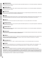
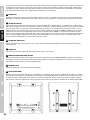
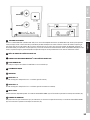
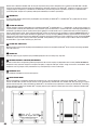
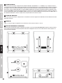
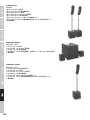
39
RELEASE BUTTON
Now slide a CURV 500
®
satellite (LD CURV 500
®
SAT) from the rear onto the SmartLink
®
adapter (LD CURV 500
®
SLA) until it stops, while
pressing the spring-loaded release button on the side of the satellite. Ensure that the two guide rails of the satellite (40) properly slide into
the grooves (41) of the SmartLink
®
adapter or of the lower satellites, in order to ensure a tight fit and establish a contact for both
components. Now release the button to lock the connection and to bring the button back to its original position. Proceed in the same manner
as described above to add other satellites.
44
44
43
43
41
41
41
39
42
41
40 40

11
DEUTSCHENGLISH FRANCAIS
ESPAÑOL
POLSKI ITALIANO
•••
41 41
48
39
47
46
45
48
40
GUIDE RAIL LD CURV 500 SATELLITE
41
GROOVES SMARTLINK
®
ADAPTER OR LD CURV 500 SATELLITE
42
M3 THREAD
M3 thread to secure the LD CURV 500
®
satellites in permanent installations.
43
LOCKING SYSTEM
44
CONTACTS
45
SATELLITE 1 / 2
Flange for 1 to 2 satellites (upright position).
46
SATELLITE 3 / 4
Flange for 3 to 4 satellites (forward tilt position).
47
INPUT SIGNAL
Speakon-compatible speaker input. The speaker input INPUT SIGNAL (47) is parallel wired with the terminal block connector (48).
48
TERMINAL BLOCK CONNECTION
Terminal block connection for permanent installation and desktop application (terminal block included). The speaker input INPUT SIGNAL
(47) is parallel wired with the terminal block connector (48).

12
DEUTSCH
ENGLISH
FRANCAIS
ESPAÑOLPOLSKI
ITALIANO
•••
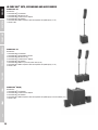
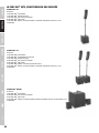
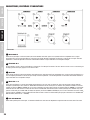
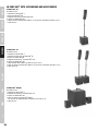
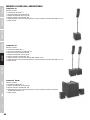
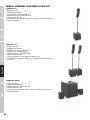
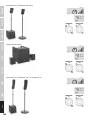
LD CURV 500
®
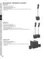
SETS, EXPANSIONS AND ACCESSORIES
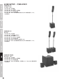
LD CURV 500
®
ES
Set Contents:
1 x LD CURV 500
®
S Subwoofer
1 x LD CURV 500
®
DB Distance Bar
1 x LD CURV 500
®
SLA SmartLink
®
Adapter
4 x LD CURV 500
®
SAT Satellite
1 x LD CURV 500
®
CABLE1 Speaker cable with Speakon-compatible plugs (2.2 m)
1 x Power cable
LD CURV 500
®
PS
Set Contents:
1 x LD CURV 500
®
S Subwoofer
1 x LD CURV 500
®
SE Subwoofer Extension
2 x LD CURV 500
®
DB Distance Bar
2 x LD CURV 500
®
SLA SmartLink
®
Adapter
8 x LD CURV 500
®
SAT Satellite
1 x LD CURV 500
®
CABLE3 5-pin XLR system cable (10 m)
2 x LD CURV 500
®
CABLE1 Speaker cable with Speakon-compatible plugs (2.2 m)
2 x Power cable
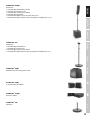
LD CURV 500
®
AVS(W)
Set Contents:
1 x LD CURV 500
®
S Subwoofer
2 x LD CURV 500
®
SLA SmartLink
®
Adapter
2 x LD CURV 500
®
SAT Satellite
2 x LD CURV 500
®
CABLE2 Speaker cable with Speakon-compatible plugs on terminal block (3 m)
1 x Power cable

13
DEUTSCHENGLISH FRANCAIS
ESPAÑOL
POLSKI ITALIANO
•••
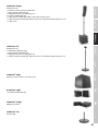
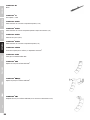
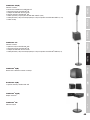
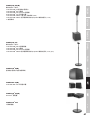
LD CURV 500
®
PES(W)
Set Contents:
1 x LD CURV 500
®
SE Subwoofer Extension
1 x LD CURV 500
®
DB Distance Bar
1 x LD CURV 500
®
SLA SmartLink
®
Adapter
4 x LD CURV 500
®
SAT Satellite
1 x LD CURV 500
®
CABLE3 5-pin XLR system cable (10 m)
1 x LD CURV 500
®
CABLE1 Speaker cable with Speakon-compatible plugs (2.2 m)
LD CURV 500
®
STS
Set Contents:
1 x LD CURV 500
®
SSB Tripod base
1 x LD CURV 500
®
DB Spacer Bar
1 x LD CURV 500
®
SLA SmartLink
®
Adapter
1 x LD CURV 500
®
CABLE4 Speaker cable with Speakon-compatible plugs (8 m)
LD CURV 500
®
SE(W)
Subwoofer Extension including power cable
LD CURV 500
®
S2(W)
2 x LD CURV 500
®
SAT Satellite
LD CURV 500
®
SLA(W)
SmartLink
®
Adapter
LD CURV 500
®
SSB
Tripod base

14
DEUTSCH
ENGLISH
FRANCAIS
ESPAÑOLPOLSKI
ITALIANO
•••
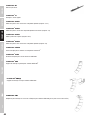
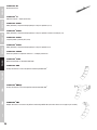
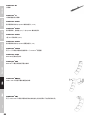
LD CURV 500
®
DB
Distance bar
LD CURV 500
®
SS
Tripod base + Distance bar
LD CURV 500
®
CABLE1
Speaker cable with Speakon-compatible plugs (2.2 m)
LD CURV 500
®
CABLE2
Speaker cable with Speakon-compatible plugs on terminal block (3 m)
LD CURV 500
®
CABLE3
5-pin XLR system cable (10 m)
LD CURV 500
®
CABLE4
Speaker cable with Speakon-compatible plugs (8 m)
LD CURV 500
®
SATBAG
Carrying Case for 4 x satellite + 2 x SmartLink
®
Adapter
LD CURV 500
®
SUBPC
Transport trolley for CURV 500 ® Subwoofer
LD CURV 500
®
CMB
Ceiling mounting bracket for LD CURV 500
®
satellites
LD CURV 500
®
WMB(W)
Ceiling mounting bracket for CURV 500
®
satellites
LD CURV 500
®
TMB
Truss mounting adapter for CURV 500 satellites (Truss clamp not included)

15
DEUTSCHENGLISH FRANCAIS
ESPAÑOL
POLSKI ITALIANO
•••
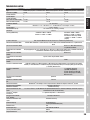
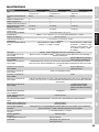
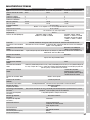
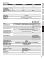
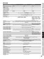
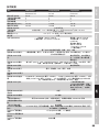
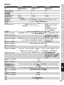
SPECIFICATIONS
Model name CURV500ES CURV500AVS CURV500PS
Type: Portable Array System Entertainer Set Portable Array System AV Set Portable Array System Power Set
Rated System Power (RMS): 460 W 380 W 920 W
Number of Satellites: 4 2 8
Number of Adaptors: 1 2 2
Number of Subwoofers: 1 1 2
Max. SPL (continuous): 122 dB 116 dB 128 dB
Max. SPL (peak): 128 dB 122 dB 134 dB
Subwoofer 500S/SE: 10“ bass reflex
Satellite: MF: 1 x 4“ / HF: 3 x 1“ with WaveAhead
®
Technology / 16 ohms
Frequency response: 47 Hz - 20 kHz
Dispersion (H x V): 110° horizontal, 10° vertical per satellite
Amplification: Class D
Power Output (RMS/Peak): Subwoofer: 300 W / 1200 W
Satellite: 2 x 160 W / 2 x 640 W
Subwoofer: 300 W / 1200 W
Satellite: 2 x 160 W / 2 x 640 W
Subwoofer Extension: 300 W /
1200 W,
1 x 160 W / 1 x 640 W (Satellite)
Protection: DSP based multiband-limiter, Short Circuit, Overheating, Over-current
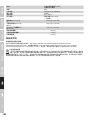
Subwoofer 500S Features: 4 channel mixer, Bluetooth
®
, 16 DFX Presets, 4 System DSP Presets, threaded M20 flange, 3 ergonomic
handels
Subwoofer 500SE Features: Ground lift, threaded M20 flange,
3 ergonomic handels
Subwoofer 500S Controls: Input Level (Ch1-4), Hi-Z, Hi/Low EQ (Ch1-2), DFX (Ch1-2), DFX Presets, DSP Presets, Blutetooth Link,
Mono/Stereo, Sub Level, Main Level
Subwoofer 500SE Controls: Ground lift
Subwoofer 500S Indicators: Signal, Limit, Clip, Bluetooth, Power
Subwoofer 500SE Indicators: Power
Subwoofer 500S Connectors: 1x Mic/Hi-Z (XLR/6,3mm Jack Combo), 1x Mic (XLR/6,3mm Jack Combo), 2x Line (XLR/6,3mm Jack
Combo), 3,5mm Jack, 2x Satellite Out (Speakon compatible), Line Out (XLR), System Out (5-pin XLR),
Mains In
Subwoofer 500SE Connectors: 1x Satellite Out (Speakon
compatible),System In (5-pin XLR),
System Out (5-pin XLR), Mains In
Subwoofer 500S/SE Material: Plywood
Subwoofer 500S/SE Surface: PA Painting
Satellite Features: WaveAhead
®
Technology, internal crossover, metal grille, SmartLink
®
System
Satellite Material: Diecast Aluminium
Satellite Surface: Powder coating
SmartLink
®
Adaptor Features: dual 16 mm flange, 4x M6 thread for optional wall/ceiling/truss mount, SmartLink
®
System,
4x rubber feet for desktop use
SmartLink
®
Adaptor
Connectors:
1x Speakon compatible, 1x Terminal block
SmartLink
®
Adaptor Material: Diecast Aluminium
SmartLink
®
Adaptor Surface: Powder coating
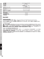
Power Supply: SMPS with PFC
Power Connector: IEC
Operating Voltage: AC 100-240V, 50/60Hz
Power Consumption (max.): 900W
Temperature Range: 0°C - 50°C
Humidity Range: 10% - 70% rel. (non condensing)
Subwoofer Dimensions
(W x H x D):
325 x 383 x 491 mm
Satellite Dimensions
(W x H x D):
122 x 122 x 122 mm
SmartLink
®
Adaptor
Dimensions (W x H x D):
122 x 57 x 122 mm
Subwoofer Weight: 16,5 kg
Satellite Weight: 1,73 kg
Adaptor Weight: 0,54 kg

16
DEUTSCH
ENGLISH
FRANCAIS
ESPAÑOLPOLSKI
ITALIANO
•••
MANUFACTURER´S DECLARATIONS
MANUFACTURER‘S WARRANTY & LIMITATIONS OF LIABILITY
You can find our current warranty conditions and limitations of liability at: http://www.adamhall.com/media/shop/downloads/documents/
manufacturersdeclarations.pdf. To request warranty service for a product, please contact Adam Hall GmbH, Daimler Straße 9, 61267 Neu
Anspach / Email: [email protected] / +49 (0)6081 / 9419-0. To enquire about the current declaration of conformity, please contact
CORRECT DISPOSAL OF THIS PRODUCT
(Valid in the European Union and other European countries with a differentiated waste collection system) This symbol on the product,
or on its documents indicates that the device may not be treated as household waste. This is to avoid environmental damage or
personal injury due to uncontrolled waste disposal. Please dispose of this product separately from other waste and have it recycled to
promote sustainable economic activity. Household users should contact either the retailer where they purchased this product, or their local
government office, for details on where and how they can recycle this item in an environmentally friendly manner. Business users should
contact their supplier and check the terms and conditions of the purchase contract. This product should not be mixed with other commercial
waste for disposal.

17
DEUTSCHENGLISH FRANCAIS
ESPAÑOL
POLSKI ITALIANO
•••
DEUTSCH
Sie haben die richtige Wahl getroffen!
Dieses Gerät wurde unter hohen Qualitätsanforderungen entwickelt und gefertigt, um viele Jahre einen reibungslosen Betrieb zu gewährleisten.
Dafür steht LD Systems mit seinem Namen und der langjährigen Erfahrung als Hersteller hochwertiger Audioprodukte. Bitte lesen Sie diese
Bedienungsanleitung sorgfältig, damit Sie Ihr neues Produkt von LD Systems schnell optimal einsetzen können.
Mehr Informationen zu LD SYSTEMS finden Sie auf unserer Internetseite WWW.LD-SYSTEMS.COM
SICHERHEITSHINWEISE
1. Lesen Sie diese Anleitung bitte sorgfältig durch.
2. Bewahren Sie alle Informationen und Anleitungen an einem sicheren Ort auf.
3. Befolgen Sie die Anweisungen.
4. Beachten Sie alle Warnhinweise. Entfernen Sie keine Sicherheitshinweise oder andere Informationen vom Gerät.
5. Verwenden Sie das Gerät nur in der vorgesehenen Art und Weise.
6. Verwenden Sie ausschließlich stabile und passende Stative bzw. Befestigungen (bei Festinstallationen). Stellen Sie sicher, dass Wandhalterungen
ordnungsgemäß installiert und gesichert sind. Stellen Sie sicher, dass das Gerät sicher installiert ist und nicht herunterfallen kann.
7. Beachten Sie bei der Installation die für Ihr Land geltenden Sicherheitsvorschriften.
8. Installieren und betreiben Sie das Gerät nicht in der Nähe von Heizkörpern, Wärmespeichern, Öfen oder sonstigen Wärmequellen. Sorgen
Sie dafür, dass das Gerät immer so installiert ist, dass es ausreichend gekühlt wird und nicht überhitzen kann.
9. Platzieren Sie keine Zündquellen wie z.B. brennende Kerzen auf dem Gerät.
10. Lüftungsschlitze dürfen nicht blockiert werden.
11. Betreiben Sie das Gerät nicht in unmittelbarer Nähe von Wasser. Bringen Sie das Gerät nicht mit brennbaren Materialien, Flüssigkeiten
oder Gasen in Berührung. Direkte Sonneneinstrahlung vermeiden!
12. Sorgen Sie dafür, dass kein Tropf- oder Spritzwasser in das Gerät eindringen kann. Stellen Sie keine mit Flüssigkeit gefüllten Behältnisse
wie Vasen oder Trinkgefäße auf das Gerät.
13. Sorgen Sie dafür, dass keine Gegenstände in das Gerät fallen können.
14. Betreiben Sie das Gerät nur mit dem vom Hersteller empfohlenen und vorgesehenen Zubehör.
15. Öffnen Sie das Gerät nicht und verändern Sie es nicht.
16. Überprüfen Sie nach dem Anschluss des Geräts alle Kabelwege, um Schäden oder Unfälle, z. B. durch Stolperfallen zu vermeiden.
17. Achten Sie beim Transport darauf, dass das Gerät nicht herunterfallen und dabei möglicherweise Sach- und Personenschäden verursachen kann.
18. Wenn Ihr Gerät nicht mehr ordnungsgemäß funktioniert, Flüssigkeiten oder Gegenstände in das Geräteinnere gelangt sind, oder das
Gerät anderweitig beschädigt wurde, schalten Sie es sofort aus und trennen es von der Netzsteckdose (sofern es sich um ein aktives Gerät
handelt). Dieses Gerät darf nur von autorisiertem Fachpersonal repariert werden.
19. Verwenden Sie zur Reinigung des Geräts ein trockenes Tuch.
20. Beachten Sie alle in Ihrem Land geltenden Entsorgungsgesetze. Trennen Sie bei der Entsorgung der Verpackung bitte Kunststoff und
Papier bzw. Kartonagen voneinander.
21. Kunststoffbeutel müssen außer Reichweite von Kindern aufbewahrt werden.
BEI GERÄTEN MIT NETZANSCHLUSS
22. ACHTUNG: Wenn das Netzkabel des Geräts mit einem Schutzkontakt ausgestattet ist, muss es an einer Steckdose mit Schutzleiter
angeschlossen werden. Deaktivieren Sie niemals den Schutzleiter eines Netzkabels.
23. Schalten Sie das Gerät nicht sofort ein, wenn es starken Temperaturschwankungen ausgesetzt war (beispielsweise nach dem Transport).
Feuchtigkeit und Kondensat könnten das Gerät beschädigen. Schalten Sie das Gerät erst ein, wenn es Zimmertemperatur erreicht hat.
24. Bevor Sie das Gerät an die Steckdose anschließen, prüfen Sie zuerst, ob die Spannung und die Frequenz des Stromnetzes mit den auf
dem Gerät angegebenen Werten übereinstimmen. Verfügt das Gerät über einen Spannungswahlschalter, schließen Sie das Gerät nur an die
Steckdose an, wenn die Gerätewerte mit den Werten des Stromnetzes übereinstimmen. Wenn das mitgelieferte Netzkabel bzw. der mitgelie-
ferte Netzadapter nicht in Ihre Netzsteckdose passt, wenden Sie sich an Ihren Elektriker.
25. Treten Sie nicht auf das Netzkabel. Sorgen Sie dafür, dass spannungsführende Kabel speziell an der Netzbuchse bzw. am Netzadapter
und der Gerätebuchse nicht geknickt werden.
26. Achten Sie bei der Verkabelung des Geräts immer darauf, dass das Netzkabel bzw. der Netzadapter stets frei zugänglich ist. Trennen Sie
das Gerät stets von der Stromzuführung, wenn das Gerät nicht benutzt wird, oder Sie das Gerät reinigen möchten. Ziehen Sie Netzkabel und
Netzadapter immer am Stecker bzw. am Adapter und nicht am Kabel aus der Steckdose. Berühren Sie Netzkabel und Netzadapter niemals mit
nassen Händen.
27. Schalten Sie das Gerät möglichst nicht schnell hintereinander ein und aus, da sonst die Lebensdauer des Geräts beeinträchtigt werden könnte.
28. WICHTIGER HINWEIS: Ersetzen Sie Sicherungen ausschließlich durch Sicherungen des gleichen Typs und Wertes. Sollte eine Sicherung
wiederholt auslösen, wenden Sie sich bitte an ein autorisiertes Servicezentrum.
29. Um das Gerät vollständig vom Stromnetz zu trennen, entfernen Sie das Netzkabel bzw. den Netzadapter aus der Steckdose.
30. Wenn Ihr Gerät mit einem verriegelbaren Netzanschluss bestückt ist, muss der passende Gerätestecker entsperrt werden, bevor er entfernt
werden kann. Das bedeutet aber auch, dass das Gerät durch ein Ziehen am Netzkabel verrutschen und herunterfallen kann, wodurch Personen
verletzt werden und/oder andere Schäden auftreten können. Verlegen Sie Ihre Kabel daher immer sorgfältig.
31. Entfernen Sie Netzkabel und Netzadapter aus der Steckdose bei Gefahr eines Blitzschlags oder wenn Sie das Gerät länger nicht verwenden.

18
DEUTSCH
ENGLISH
FRANCAIS
ESPAÑOLPOLSKI
ITALIANO
•••
CAUTION
RISK OF ELECTRIC SHOCK
DO NOT OPEN
ACHTUNG
Entfernen Sie niemals die Abdeckung, da sonst das Risiko eines elektrischen Schlages besteht.
Im Inneren des Geräts befinden sich keine Teile, die vom Bediener repariert oder gewartet werden
können. Lassen Sie Reparaturen ausschließlich von qualifiziertem Servicepersonal durchführen.
Das gleichschenkelige Dreieck mit Blitzsymbol warnt vor nichtisolierten, gefährlichen Spannungen im Geräteinneren, die einen
elektrischen Schlag verursachen können.
Das gleichschenkelige Dreieck mit Ausrufungszeichen kennzeichnet wichtige Bedienungs- und Wartungshinweise.
ACHTUNG HOHE LAUTSTÄRKEN BEI AUDIOPRODUKTEN!
Dieses Gerät ist für den professionellen Einsatz vorgesehen. Der kommerzielle Betrieb dieses Geräts unterliegt den jeweils gültigen
nationalen Vorschriften und Richtlinien zur Unfallverhütung. Als Hersteller ist Adam Hall gesetzlich verpflichtet, Sie ausdrücklich auf mögliche
Gesundheitsrisiken hinzuweisen.
Gehörschäden durch hohe Lautstärken und Dauerbelastung: Bei der Verwendung dieses Produkts können hohe Schalldruckpegel (SPL)
erzeugt werden, die bei Künstlern, Mitarbeitern und Zuschauern zu irreparablen Gehörschäden führen können.
Um eine mögliche Schädigung des Hörsinns zu verhindern, vermeiden Sie das Hören bei großem Lautsärkepegel über lange
Zeiträume.
Lauter Schalleinfluss kann selbst bei kurzer Dauer zu Hörschäden führen. Bitte halten Sie die Laustärke immer auf einem
angenehmen Level.
* CURV500S, CURV500SE sind für den Betrieb unter den elektromagnetischen Gegebenheiten in folgenden Umgebungen geeignet:
Wohn-, Geschäfts und Leichtindustrieumgebungen und im städtischen Außenbereich. Die Geräte eignen sich nicht für die Rackmontage.
* Einschaltspitzenstrom: 8,86 A
* Dieses Gerät entspricht den Anforderungen in Abschnitt 15 der FCC. Für den Betrieb müssen zwei Forderungen erfüllt sein: (1) Das Gerät darf
keine störenden Interferenzen verursachen und (2) das Gerät muss alle externen Interferenzen akzeptieren, auch wenn diese eine unerwünschte
Beeinflussung des Betriebs verursachen. Jede Veränderung oder Modifikation des Geräts, die nicht ausdrücklich von der für die Einhaltung der
rechtlichen Bestimmungen zuständigen Person freigegeben wurde, kann das Erlöschen der Betriebszulassung zur Folge haben.
HINWEIS: Dieses Gerät wurde getestet und entspricht den Grenzwerten digitaler Geräte der Klasse B gemäß Abschnitt 15 der FCC-Bestimmungen.
Diese Grenzwerte bieten ausreichenden Schutz gegen Interferenzen bei der Installation in Wohnräumen. Dieses Gerät erzeugt und nutzt
hochfrequente Energie und kann sie ausstrahlen. Wenn es nicht nach den Anweisungen des Herstellers aufgestellt und betrieben wird,
können Störungen im Radio-/Fernsehempfang auftreten. In diesem Sinne kann nicht zugesichert werden, dass in bestimmten Installationen
keine Einstreuungen auftreten. Wenn dieses Gerät störend in den Radio- und/oder Fernsehempfang einstreut und dieser Zustand durch
Ein- und Ausschalten des Geräts verifiziert werden kann, sollte der Anwender versuchen, die Einstreuungen durch eine oder mehrere der
folgenden Maßnahmen aufzuheben:
- Richten Sie die Empfangsantenne neu aus oder stellen Sie diese anders auf.
- Vergrößern Sie den Abstand zwischen dem Gerät und dem Empfänger.
- Schließen Sie das Gerät an einen anderen Stromkreis an, mit dem der Empfänger nicht verbunden ist.
- Wenden Sie sich bei Problemen an Ihren Händler oder an einen erfahrenen Radio-/TV-Techniker.
EINFÜHRUNG
Das kompakte, besonders transportfreundliche CURV 500
®
ist ein leicht konfigurierbares Array-System mit maximal 4 ineinander verriegelnden
Satelliten, die an einem SmartLink
®
-Adapter betrieben werden. Die nur 12 x 12 cm großen Elemente sind mit LD Systems eigener
WaveAhead
®
-Technik ausgestattet, ein 4“ und drei 1“ Treiber sorgen für eine kohärente und extrem detaillierte Wiedergabe mit hohem Druck
und Dynamik.
Der 10“ Bassreflex-Subwoofer beherbergt die DSP gesteuerte Class-D-Verstärkung des CURV 500
®
mit Limiter, Schutz gegen Kurzschluss,
Überhitzung und Überspannung sowie einen 4-Kanal-Mixer mit 16 digitalen Effekt-Presets und Bluetooth
®
. Combo- und speakON-kompatible
Buchsen bieten umfangreiche Anschlussmöglichkeiten, dazu besitzt der Subwoofer 4 digitale System-Presets, einen M20-Gewindeflansch und
3 ergonomische Tragegriffe. In 3 Sets für den mobilen und fixen Einsatz erhältlich, zeichnet sich die bequeme Gesamtlösung CURV 500
®
durch
geringes Gewicht und eine breite, weitreichende Abstrahlung aus.

19
DEUTSCHENGLISH FRANCAIS
ESPAÑOL
POLSKI ITALIANO
•••
D
C
B
A
G
C
F
E
H
Allgemeine Hinweise
Der Subwoofer des LD Systems CURV 500
®
Array-Systems muss vor der Inbetriebnahme senkrecht auf ebener Fläche auf seine Füße gestellt
werden. Betreiben Sie das System niemals auf einem Rollwagen, da die Gefahr besteht, dass sich das gesamte System unkontrolliert in
Bewegung setzt. Unfälle und Beschädigungen können die Folge sein. Um eine ausreichende Kühlung zu gewährleisten, muss bei Betrieb
zwischen der Rückseite des Subwoofers und anderen Objekten wie Wänden o. ä. ein Mindestabstand von 50 cm eingehalten werden.
Bitte achten Sie bei dem System sowie den angeschlossenen Geräten wie Mischpulten, CD-Playern etc. auf den korrekten Anschluss von
Audio- und Stromverbindungen. Verwenden Sie ausschließlich unbeschädigte Kabel mit geeignetem Durchmesser und rollen Sie Kabelrollen
immer vollständig ab. Verwenden Sie gegebenenfalls Kabelbrücken, um Stolperfallen durch lose Kabel zu vermeiden. Stellen Sie das Gerät
niemals direkt an einer Kante auf. Positionieren Sie den Subwoofer nicht auf einem Tisch. Um ungewollte Nebengeräusche beim Einschalten
angeschlossener Geräte zu vermeiden, schalten Sie das System immer als letztes Gerät ein und als erstes Gerät aus.
AUFBAU
Um eine Vielzahl verschiedener Konfigurationsmöglichkeiten zu ermöglichen, ist das LD Systems CURV 500
®
Array-System modular aufgebaut.
Repräsentativ steht nachfolgend beschrieben der Aufbau des LD CURV 500
®
ES Entertainer Sets. Beispiele weiterer Sets finden Sie auf den
folgenden Seiten dieser Anleitung.
Das LD CURV 500
®
ES Entertainer Set besteht aus 4 Komponenten:
A. Subwoofer mit Mischpult, integriertem DSP (Digitaler Signalprozessor) und Class-D Endstufen für die Systemkomponenten.
B. Höhenverstellbare Distanzstange.
C. SmartLink
®
Adapter als Basis für bis zu 4 CURV 500
®
Array Satelliten.
D. Vier CURV 500
®
Array Satelliten mit patentiertem Klick-Mechanismus und WaveAhead
®
Technologie.
Nachdem der Subwoofer (A) an einer geeigneten Stelle aufgestellt wurde, wird die Distanzstange (B) auf den Subwoofer aufgeschraubt
(Flansch auf der Oberseite). Bei der Verwendung von 1 oder 2 CURV 500
®
Satelliten stecken Sie nun den SmartLink
®
Adapter (C) mit dem
hinteren Flansch (Markierung Satellite 1 + 2, aufrechte Position, Abb. E) oben auf die Distanzstange, bei der Verwendung von 3 oder 4
CURV 500
®
Satelliten mit dem vorderen Flansch (Markierung Satellite 3 + 4, nach vorn geneigte Position, Abb. F). Schieben Sie nun einen
CURV 500
®
Satelliten (D) von hinten auf den SmartLink
®
Adapter (C) bis zum Anschlag, während Sie den gefederten Entriegelungsknopf
an der Seite des Satelliten drücken. Achten Sie dabei darauf, dass die beiden Führungsschienen des Satelliten korrekt in die Nuten auf
der Oberseite des SmartLink
®
Adapters eingeführt werden, um einen festen Sitz zu gewährleisten und die Verbindung der Kontakte beider
Komponenten herzustellen. Lösen Sie nun den Druck auf den Entriegelungsknopf um ihn wieder in die Ursprungsposition zu bringen und
die Verbindung zu verriegeln. Gehen Sie in der gleichen, zuvor beschriebenen Weise vor, um das System um weitere Satelliten zu erweitern.
Verbinden Sie nun den Lautsprecher-Ausgang SATELLITE OUT des CURV 500
®
Subwoofers mit dem Lautsprecher-Eingang INPUT SIGNAL (G)
des SmartLink
®
Adapters mit Hilfe des mitgelieferten Lautsprecherkabels.
Beim Abbau gehen Sie bitte in umgekehrter Reihenfolge vor. Für die feste Installation und Desktop-Anwendung befindet sich auf der Rück-
seite des SmartLink
®
Adapters ein Klemmblock-Anschluß (Abb. H, Klemmblock im Lieferumfang). Der Lautsprecher-Eingang INPUT SIGNAL
(G) ist mit dem Klemmblock-Anschluß (H) parallel verkabelt.

20
DEUTSCH
ENGLISH
FRANCAIS
ESPAÑOLPOLSKI
ITALIANO
•••
ANSCHLÜSSE, BEDIEN- UND ANZEIGEELEMENTE
1 3 4 4
5 6
7
2
8 9 10 10
LDCURV500S
1
INPUT MIC/HI-Z
Symmetrischer Mikrofon-, bzw. Instrumenten-Eingang (XLR / 6,3 mm Klinke Combo). Die Nutzung von unsymmetrischen Mikrofon- bzw.
Instrumentenkabeln (Mono-Klinke) ist ebenfalls möglich. Achten Sie auf die Einstellung des Schalters 2, wie nachfolgend beschrieben.
Hinweis: An der XLR-Eingangsbuchse liegt für die Spannungsversorgung eines Kondensatomikrofons eine 12V Phantomspeisung an.
2
HI-Z SCHALTER
Bei der Verwendung des Kanals 1 als Mikrofonkanal, bringen Sie den HI-Z Schalter in die nicht heruntergedrückte Position. Als Instrumenten-Kanal
genutzt (z.B. Gitarre), bringen Sie den HI-Z Schalter in die heruntergedrückte Position.
3
INPUT MIC
Symmetrischer Mikrofon-Eingang (XLR / 6,3 mm Klinke Combo). Die Nutzung eines unsymmetrischen Mikrofonkabels (Mono-Klinke) ist
ebenfalls möglich. Hinweis: An der XLR-Eingangsbuchse liegt für die Spannungsversorgung eines Kondensatomikrofons eine 12V
Phantomspeisung an.
4
INPUT LINE 3 + 4
Symmetrische Line-Eingänge mit XLR / 6,3 mm Klinke Combo-Buchsen zum Anschließen eines Zuspielgeräts (z.B. Mischpult, Keyboard). Bei
der Verwendung eines CURV 500
®
ES Entertainer Sets als Mono-Set (die Array Satelliten zusammen auf der Distanz-Stange montiert), muss
der Schalter MONO / STEREO (26) auf dem Mischpult-Bedienfeld heruntergedrückt sein (MONO). Das anliegende Audio-Signal wird nun
Mono summiert. Wird das CURV 500
®
ES Entertainer Set als Stereo-Set verwendet (Aufstellung von je 2 Array Satelliten links und rechts),
bzw. das CURV 500
®
PS Power Set (Stereo) eingesetzt, bringen Sie den Schalter MONO / STEREO (26) in die nicht heruntergedrückte
Position STEREO. Ein anliegendes Stereo Audio-Signal wird in Stereo ausgegeben. Letzteres gilt auch bei der Verwendung des LD CURV
500
®
AVS Stereo A/V Sets (Schalter 26 -> STEREO).
5
LINE OUT MONO MIX
Symmetrischer Line-Ausgang mit männlicher XLR-Buchse. Ausgabe des Mischpult Summen-Signals in Mono.
Seite laden ...
Seite laden ...
Seite laden ...
Seite laden ...
Seite laden ...
Seite laden ...
Seite laden ...
Seite laden ...
Seite laden ...
Seite laden ...
Seite laden ...
Seite laden ...
Seite laden ...
Seite laden ...
Seite laden ...
Seite laden ...
Seite laden ...
Seite laden ...
Seite laden ...
Seite laden ...
Seite laden ...
Seite laden ...
Seite laden ...
Seite laden ...
Seite laden ...
Seite laden ...
Seite laden ...
Seite laden ...
Seite laden ...
Seite laden ...
Seite laden ...
Seite laden ...
Seite laden ...
Seite laden ...
Seite laden ...
Seite laden ...
Seite laden ...
Seite laden ...
Seite laden ...
Seite laden ...
Seite laden ...
Seite laden ...
Seite laden ...
Seite laden ...
Seite laden ...
Seite laden ...
Seite laden ...
Seite laden ...
Seite laden ...
Seite laden ...
Seite laden ...
Seite laden ...
Seite laden ...
Seite laden ...
Seite laden ...
Seite laden ...
Seite laden ...
Seite laden ...
Seite laden ...
Seite laden ...
Seite laden ...
Seite laden ...
Seite laden ...
Seite laden ...
Seite laden ...
Seite laden ...
Seite laden ...
Seite laden ...
Seite laden ...
Seite laden ...
Seite laden ...
Seite laden ...
Seite laden ...
Seite laden ...
Seite laden ...
Seite laden ...
Seite laden ...
Seite laden ...
Seite laden ...
Seite laden ...
Seite laden ...
Seite laden ...
Seite laden ...
Seite laden ...
Seite laden ...
Seite laden ...
Seite laden ...
Seite laden ...
Seite laden ...
Seite laden ...
Seite laden ...
Seite laden ...
Seite laden ...
Seite laden ...
Seite laden ...
Seite laden ...
Seite laden ...
Seite laden ...
Seite laden ...
Seite laden ...
-
 1
1
-
 2
2
-
 3
3
-
 4
4
-
 5
5
-
 6
6
-
 7
7
-
 8
8
-
 9
9
-
 10
10
-
 11
11
-
 12
12
-
 13
13
-
 14
14
-
 15
15
-
 16
16
-
 17
17
-
 18
18
-
 19
19
-
 20
20
-
 21
21
-
 22
22
-
 23
23
-
 24
24
-
 25
25
-
 26
26
-
 27
27
-
 28
28
-
 29
29
-
 30
30
-
 31
31
-
 32
32
-
 33
33
-
 34
34
-
 35
35
-
 36
36
-
 37
37
-
 38
38
-
 39
39
-
 40
40
-
 41
41
-
 42
42
-
 43
43
-
 44
44
-
 45
45
-
 46
46
-
 47
47
-
 48
48
-
 49
49
-
 50
50
-
 51
51
-
 52
52
-
 53
53
-
 54
54
-
 55
55
-
 56
56
-
 57
57
-
 58
58
-
 59
59
-
 60
60
-
 61
61
-
 62
62
-
 63
63
-
 64
64
-
 65
65
-
 66
66
-
 67
67
-
 68
68
-
 69
69
-
 70
70
-
 71
71
-
 72
72
-
 73
73
-
 74
74
-
 75
75
-
 76
76
-
 77
77
-
 78
78
-
 79
79
-
 80
80
-
 81
81
-
 82
82
-
 83
83
-
 84
84
-
 85
85
-
 86
86
-
 87
87
-
 88
88
-
 89
89
-
 90
90
-
 91
91
-
 92
92
-
 93
93
-
 94
94
-
 95
95
-
 96
96
-
 97
97
-
 98
98
-
 99
99
-
 100
100
-
 101
101
-
 102
102
-
 103
103
-
 104
104
-
 105
105
-
 106
106
-
 107
107
-
 108
108
-
 109
109
-
 110
110
-
 111
111
-
 112
112
-
 113
113
-
 114
114
-
 115
115
-
 116
116
-
 117
117
-
 118
118
-
 119
119
-
 120
120


LD Systems CURV 500 ES Portable Column PA System 2400W Benutzerhandbuch
- Typ
- Benutzerhandbuch
in anderen Sprachen
- English: LD Systems CURV 500 ES Portable Column PA System 2400W User manual
- français: LD Systems CURV 500 ES Portable Column PA System 2400W Manuel utilisateur
- español: LD Systems CURV 500 ES Portable Column PA System 2400W Manual de usuario
- italiano: LD Systems CURV 500 ES Portable Column PA System 2400W Manuale utente
- polski: LD Systems CURV 500 ES Portable Column PA System 2400W Instrukcja obsługi
Verwandte Papiere
-
LD Systems CURV 500 TS Bedienungsanleitung
-
LD Systems Curv 500 IAMP Benutzerhandbuch
-
LD Systems CURV 500 I AMP Benutzerhandbuch
-
LD Systems CURV 500 S2 W Benutzerhandbuch
-
LD LDMIX62AG3 Benutzerhandbuch
-
-
LD Systems LD System CURV 500 D SAT Duplex Satellite Bedienungsanleitung
-
-
LD Systems CURV 500 SLA T Benutzerhandbuch
-
