
GCE HEALTHCARE
INSTRUCTIONS FOR USE
ANVÄNDARANVISNING
NÁVOD K POUŽITÍ
HASZNÁLATI ÚTMUTATÓ
GEBRAUCHSANWEISUNG
MMR
HIGH PRESSURE REGULATORS
HÖGTRYCKS REDUCERINGSVENTILER
VYSOKOTLAKÉ REDUKČNÍ VENTILY
MAGASNYOMÁSÚ NYOMÁSCSÖKKENTŐK
EN
SV
CS
HU
DE
HOCHDRUCKREGLER

2/44
EN 1. FOREWORD
GCE Medical Regulators are medical devices classified as class IIb accord-
ing to the Medical Device Directive 93/42/EEC.Their Compliance with essen-
tial requirements of 93/42/EEC Medical Device Directive is based upon ISO
10524-1 standard.
2. INTENDED USE
GCE Medical Regulators are designed for use with high-pressure medical gas
cylinders equipped with a medical cylinder shut-o valve and in pipeline sys-
tems. They regulate pressure and flow of medical gases to the patient. They
are intended for the administration of the following medical gases in the treat-
ment, management, diagnostic evaluation and care of the patient.
Basic variants (divided by gas type):
• oxygen;
• xenon;
• nitrous oxide;
• specified mixtures of the gases listed;
• air for breathing;
• air to power surgical tools;
• helium;
• nitrogen to power surgical tools;
• carbon dioxide
3. OPERATIONAL, TRANSPORT AND STORAGE
SAFETY REQUIREMENTS
Keep the product and its associated equipment from:
• heat sources (fire, cigarettes,...),
• flammable materials,
• oil or grease (especially be careful in use of hand cream),
• water,
• dust.
The product and its associated equipments must be prevented from falling
over.
Always maintain oxygen cleanliness standards.
Use the product and its associated equipment in well ventilated areas only.
ENGLISH
INSTRUCTION FOR USE: MMR PRESSURE REGULATORS

3/44
EN
Before initial use, the product must be kept in its original packaging.
GCE recommends use of the original packaging (including internal sealing
bag and caps) if the product is withdrawn from operation (for transport,
storage).
Statutory laws, rules, and regulations for medical gases, occupational safe-
ty, and environmental protection must be observed.
OPERATING CONDITIONS STORAGE AND TRANSPORT
CONDITIONS
-20/+60 °C -30/+60 °C
10/100 % 10/100 %
600/1200 mbar 600/1200 mbar
4. PERSONNEL INSTRUCTIONS
The Medical Devices Directive 93/42/EEC states that product provider
must ensure that all personnel handling the product are provided with the
operating instructions & performance data.
Do not use the product without properly familiarization of the product
and its safe operation as defined in this Instruction for use. Ensure user
is aware of particular information and knowledge required for the gas
in use.
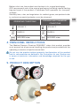
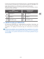
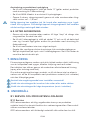
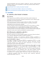
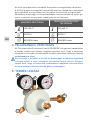
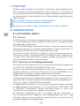
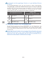
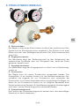
5. PRODUCT DESCRIPTION
A
BC
E
D

4/44
EN
A - Inlet stem
The regulator is fitted to the medical cylinder valve and to the pipeline
system by means of an inlet stem. The stem’s nut can be female or male
threaded. The inlet stem contains a filter.
B - Inlet pressure gauge
The pressure gauge is designed to indicate cylinder contents (the medical
cylinder shut-o valve must be set to the ON position to allow pressure
measuring).
C - Outlet pressure gauge
The pressure gauge is designed to indicate outlet pressure in the valve
and in the pipeline system.
D - Pressure outlet
The regulator may be fitted with a pressure outlet. The pressure outlet is a
direct outlet from the low-pressure chamber. One type of pressure
outlet is used: The pressure outlet is fitted with a threaded connector.
Regulators with this type of pressure outlet can only be used as an integral
part of a unit of medical equipment (e.g. emergency ventilator, anaesthesia
device, etc.) or in a pipeline system.
E - Pressure relief valve
Function of the pressure relief valve is to relief excessive overpressure
in the valve.
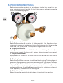
6. OPERATIONS
6.1. BEFORE USE
Visual Inspection before use
• Check whether there is visible external damage to the regulator or to the
gas cylinder (including product labels and marking). If they show signs
of external damages, remove them from service and identify their status.
• Check visually whether the regulator or the medical gas cylinder is con-
taminated; if needed, clean the regulator in accordance with the clean-
ing procedure detailed hereinafter, (in case of cylinder contamination,
refer to the gas cylinder manufacturer cleaning recommendations).
• Check whether the relevant product service term or the total life time of
the GCE product and of the gas cylinder have not been exceeded (refer
to date coding system of GCE or of the owner). If the service term or the
life time has been exceeded, remove the regulator (or the gas cylinder)
from service & identify its status appropriately.
• Ensure that the product inlet stem is compatible with the medical cylin-
der valve (gas/ thread type).
• Check the presence & integrity of the inlet stem seals / correct size of
seal.

5/44
EN
Remove the protection cap from the inlet and/or flow outlet. Keep the
caps in a safe place for possible reuse during transport or storage. The
product is intended for use only with the gas specified on its label. Never
try to use it for another gas!
Fitting to the medical cylinder valve
• Secure the gas cylinder’s position.signs of external damages, remove
them from service and identify their status.
Screw connection (with male or female thread)
• Manually screw the thread onto the cylinder valve connector.
• Turn the regulator into the correct position for use and tighten the nut by
hand - do not use tools.
• Position the equipment in such way so that the regulator user outlets
point away from personnel.
Fitting the regulator to the cylinder valve with too high torque may result
in damage.
When fitting the regulator to the cylinder valve, do not apply torque/ load
to any other parts of the product.
Leakage check before use
• Slowly open the cylinder valve by turning the hand wheel in anticloc
wise direction approx. 1 to 1½ turns.
Sudden opening of the cylinder valve could cause danger of fire or ex-
plosion arising from oxygen pressure shock. Insucient opening of the
cylinder valve could reduce actual flow delivered.
• Check visually and acoustically for possible leakages on:
• the regulator inlet connection to the cylinder valve,
• the pressure relief valve vent hole(s),
• the pressure gauge connection to the main body,
• Turn o the cylinder valve by turning the hand wheel in a clockwise direc-
tion to the “stop” position. Do not use excessive force.
If any leakage is detected, use the procedure in chapter 6.3 and return
the product to GCE for service.
Functional checks before use
• Ensure that the cylinder valve is open, i.e. in the “ON” position.
• Check that the gauge indicates pressure.
• Turn o the cylinder valve by turning the hand wheel in a clockwise di-
rection to the “stop” position. Do not use excessive force.
• For regulators fitted with a pressure outlet, ensure it is functional by con-
necting and disconnecting an output extension.

6/44
EN
6.2. USER OUTLETS CONNECTION & USE
List of recognised accessories
Hoses, flow meters, ventilators, low pressure regulators.
To be connected to the pressure outlet:
Ventilators
Before connecting any accessory or medical device to the regulator, al-
ways check that it is fully compatible with the product connection fea-
tures & the product version.
Pressure outlet connection
Pressure outlet
• Ensure that the extension is compatible with the pressure outlet.
• Connect the extension.
• Check correct connection of the extension.
Regulators with threaded connector as pressure outlet can only be used
as an integral part of a medical equipment unit. Do not use them for other
purposes!
Sudden opening of the cylinder valve could cause danger of fire or ex
plosion arising from oxygen pressure shock. Insucient opening of the
cylinder valve could reduce actual flow delivered.
The oxygen flow rate must be prescribed and administered by a clinically
trained user.
Use of the product pressure outlet
• Ensure that the flow control knob is in the ZERO position (only for pro
ucts with flow measuring devices).
• Ensure that the accessory IS NOT connected to the pressure outlet.
• Slowly open the cylinder valve by turning the hand wheel in anticlock-
wise direction approx. 1 to 1½ turns.
Sudden opening of the cylinder valve could cause danger of fire or ex-
plosion arising from oxygen pressure shock. Insucient opening of the
cylinder valve could reduce actual flow delivered.
6.3. AFTER USE
• Turn o the cylinder valve by turning the hand wheel in a clockwise di-
rection to the „stop“ position. Do not use excessive force.
• Ensure that the flow control knob is set to the “ZERO” value until the flow
control device reaches the correct position (only for products with flow
measuring devices).
• Check that the pressure gauge does not indicate any residual pressure.
• Disconnect all devices connected to the user outlets.
• Refit pressure outlet and flow outlet protection caps. Before retting the
caps, ensure that they are clean.

7/44
EN
7. CLEANING
Remove general contamination with a soft cloth damped in oil free,
oxygen compatible, soapy water, & rinse with clean water.
Disinfection can be carried out with an alcohol-based solution (spray or
wipes). If other cleaning solutions are used, check that they are not abra-
sive and that they are compatible with the product materials (including
labels) and gas.
Do not use cleaning solutions containing ammonia!
Do not expose the device to influences of water or any other liquids.
Do not expose to high temperatures (such as in an autoclave).
8. MAINTENANCE
8.1. SERVICE AND PRODUCT LIFE TIME
8.1.1. Service
GCE recommend that a Periodic inspection of the product is undertaken
every year, including check of proper functionality of the regulator. It
should be done by a skilled technician.
GCE recommend that Overall maintenance is performed after 5 years of
operation. Such maintenance consists of preventive operational mainte-
nance including replacement of critical components and re-testing of the
product. Overall maintenance can be carried out by GCE authorised per-
son only.
We have to warn that the Periodic Inspections and Overall Maintenance
recommended by GCE do not necessarily cover every safety procedure or
practice required by local regulations or statutory requirements and that
abnormal or unusual circumstances can cause further requirements or a
ditional procedures.
8.1.2. Life time and waste management
Maximum life time of the product is 10 years.
At the end of the product’s life time, the product must be taken out of ser-
vice. The device owner must prevent any future use of the product (mark-
ing, etc.).
The provider of the device shall prevent the reuse of the product and
handle the product in compliance with “Directive of European Parliament
and Council 2008/98/EC on waste“.
In accordance to Article 33 of REACH GCE, s.r.o. as responsible
manufacturer shall inform all customers if materials containing 0.1% or
more of substances included in the list of Substance of Very High Concern
(SVHC).

8/44
EN
The most commonly used brass alloys used for bodies and other brass
components contain 2-3% of lead (Pb), EC no. 231-468-6, CAS no. 7439-
92-1. The lead will not be released to the gas or surrounding environment
during normal use. After end of life the product shall be scrapped by an
authorized metal recycler to ensure ecient material handling with minimal
impact to environment and health.
To date we have no information that indicates that other materials
containing SVHC of concentrations exceeding 0.1% are included in any
GCE product.
8.2. REPAIRS
Repair activities cover the replacement of the following damaged or
missing components:
• Inlet stem
• Diaphragms of the 1st a 2nd level
• Inlet pressure gauge
• Throttling devices of the 1st a 2nd level
• Outlet pressure gauge
• Pressure relief valve
• Outlet connector
Repairs can be carried out by a GCE authorised person only.
Any product sent back to a GCE authorised person for maintenance must
be properly packaged.
The reason for the maintenance has to be clearly specifi ed (repair, overall
maintenance). A short description of the fault and the claim number
reference should accompany any product sent for repair.
Some repair activities concerning replacement of damaged or missing
components can be carried out by the owner of the product. Only the
following parts can be replaced:
• Caps
• Hose nipple
• Stickers
• Inlet stem seals
All labels on the product must be kept in good, legible condition by the
owner and the user during the entire product life time.
All seals and o-rings must be kept in dry, dark, and clean environment by
the owner and the user during the entire product life time.
Use only original GCE components!

9/44
EN
MANUFACTURER:
GCE, s.r.o. Tel : +420 569 661 111
Zizkova 381 Fax : +420 569 661 602
583 01 Chotebor http://www.gcegroup.com
Czech Republic © GCE, s.r.o.
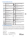
9. GLOSSARY
Consult instruction
for use Suitable for Hospital care
use
Humidity limit Suitable for Home care
use use
Caution Suitable for Emergency
care use
Keep away from heat
and flammable material Temperature limit
Keep away from oil and
grease Serial number
Keep dry Catalogue number
Fragile, handle with
care Batch code
Date of manufacture Manufacturer
Use by date
Outlet parameter
Inlet parameter (P1)
10. WARRANTY
The Standard Warranty period is two years from date of receipt by the GCE
Customer (or if this is not known 2 years from time of the product manufac-
ture shown on the product).
The standard warranty is only valid for products handled according to
Instruction for use (IFU) and general industry good practice and standards.

10/44
SV
1. FÖRORD
Reduceringsventilerna från GCE är medicinsktekniska apparaterklassifi ce-
rade i klass IIb enl. direktivet om medicinsktekniska apparater
93/42/EEC.
Överensstämmelse med kraven i direktivet 93/42/EEG baseras på norm
ISO 10524-1.
2. ANVÄNDNINGSOMRÅDEN
Reduceringsventilerna är avsedda att anslutas till högtrycksfl askor
försedda med stängningsventil och till ledningsnät. De reducerar tryck och
flöde hos medicinska gaser som ges till patienter. De är avsedda för ned-
anstående medicinska gaser vid behandling, administration, diagnostik
och vård av patienter:
Basic variants (divided by gas type):
• syrgas;
• xenon;
• lustgas (dikväveoxid);
• blandningar av ovanstående gaser;
• medicinsk luft;
• luft för drivning av kirurgiska instrument;
• helium;
• kvävgas för drivning av kirurgiska instrument.
• koldioxid
3. SÄKERHETSKRAV VID DRIFT, TRANSPORT OCH
FÖRVARING
Håll produkten, inkl. tillbehör, bortom påverkan från:
• värmekällor (eld, cigaretter, …),
• brännbara material,
• olja eller fett,
• vatten,
• damm.
Produkten, inkl. tillbehör, skall vara skyddad mot vältning
Följ alltid renlighetsföreskrifter för syrgas.
Använd endast produkten, inkl. tillbehör, i väl ventilerade utrymmen.
SVENSKA
ANVÄNDARANVISNING: MMR REDUCERINGSVENTILER

11/44
SV
Före första användning skall produkten förvaras i originalemballaget. GCE
rekommenderar användning av originalförpackningen (inkl. plastpåsar och
kåpor) då produkten tas ur drift (ex.vis vid transport, förvaring).
Nationella lagar, kungörelser och föreskrifter för medicinska gaser, arbetar-
skydd och miljö skall följas.
DRIFT
FÖRUTSÄTTNINGAR
LAGRING OCH
TRANSPORT
-20/+60 °C -30/+60 °C
10/100 % 10/100 %
600/1200 mbar 600/1200 mbar
4. INSTRUKTION AV PERSONAL
EU-direktivet 93/42/EEG om medicintekniska produkter föreskriver, att
den som levererar produkten, skall se till att all personal som hanterar
produkten, har tillgång till bruksanvisning och information om tekniska
data.
Använd inte produkten utan att ordentligt känna produkten och hur den
används på ett säkert sätt enligt Bruksanvisningen. Se till att användaren
har kännedom om specifik information och kunskaper gällande den gas
som används.

12/44
SV
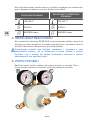
5. PRODUKTBESKRIVNING
Reduceringsventilen används för att reducera trycket hos gaser från gasfl
aska, eller ledningsnät. Gas från fl aska fl ödar genom reduceringsventilen
fram till användarutgångarna.
A
BC
E
D
A - Ingångsanslutning
Reduceringsventilen är ansluten till ledningsnätet, eller fl askans stäng-
ningsventil genom en ingångsanslutning. Anslutningen skall ha en mutter
med inre, eller yttre gänga. I ingångsanslutningen sitter ett fi lter.
B - Ingångsmanometer
Ingångsmanometern är avsedd till att avläsa innehållet i gasfl askan (för
avläsning av trycket i fl askan skall fl askans stängningsventil vara öppen).
C - Utgångsmanometer
Manometern är avsedd till att avläsa trycket från ventilen och från ledning
nätet.
D - Tryckutgång
Reduceringsventilen kan vara försedd med tryckutgång. Tryckutgången är
en direkt utgång från lågtryckskammaren. En typ av tryckutgång används:
Tryckutgången är försedd med en gängad anslutning. Reduceringsventiler
med denna typ av tryckutgång får endast användas som en odelbar enhet
av den medicinska utrustningen(ex.vis ventilator för ambulansvård, anest
tiska apparater), eller ansluten till ledningsnät.
E - Säkerhetsventil
Säkerhetsventilen används för att släppa ut övertryck från ventilen.

13/44
SV
6. DRIFT
6.1. FÖRE ANVÄNDNING
Visuell kontroll före användning
• Kontrollera att reduceringsventilen, eller fl askan, inte är synbarligen
skadade (inkl. etiketter och märkningar). I så fall skall produkten tas ur
drift och dess skick märkas ut.
• Kontrollera visuellt att reduceringsventilen, eller fl askan för medicinska-
gaser inte är förorenade. Rengör vid behov reduceringsventilen enligt-
den arbetsgång som beskrivs nedan i detta dokument (om fl askan är
förorenad, gå till väga enl. de rekommendationer för rengöring som fi
nns i fl asktillverkarens anvisningar).
• Kontrollera att tidpunkt för service, eller livslängd hos GCE-produkten,
eller gasfl aska inte har överskridits (enl. ägarens, eller GCE:s datumkod-
ning). Om tidpunkt för service, eller livslängd har överskridits, skall redu-
ceringsventilen (eller gasfl askan) tas ur drift och märkas på lämpligt sätt.
• Se till så att produktens ingångsanslutning är kompatibel med fl askven-
tilen för medicinskt bruk (gas/typ av gänga).
• Kontrollera att tätningar fi nns på ingångsanslutningen och att dessa är
korrekta och har rätt storlek.
Ta bort skyddslocket från ingångsanslutningen och/eller fl ödesutgång-
en. Förvara locken på säker plats i fall dessa behöver användas återigen
vid transport, eller förvaring.
Produkten är endast avsedd att användas med den gas som anges på
etiketten. Försök aldrig använda den med annan gas.
Anslutning till fl askventil för medicinskt bruk
• Förankra fl askan i säkertläge.
Skruvanslutning (typ med inre, eller yttre gänga)
• Skruva i gängan i fl askventilens anslutning.
• Vrid reduceringsventilen till rätt användarläge och dra åt muttern - an-
vänd verktyg.
• Ställ upp fl askan med reduceringsventilen så, att användarutgången
inte pekar i riktning mot personalen.
Anslutning av reduceringsventilen med användning av för stort vridmo-
ment på fl askventilen, kan medföra att den skadas.
Använd varken andra delar av produkten, eller belasta den vid anslutning
till flaskventilen.
Täthetsprov före användning
• Öppna fl askans stängningsventil genom att vrida manöverratten lång-
samt moturs ca 1 – 1,5 varv.

14/44
SV
Häftig öppning kan medföra risk för brand eller explosion p.g.a. tryck-
chock från syrgasen. Otillräckligt öppnad stängningsventil kan medföra
att det verkliga matningsfl ödet minskas.
• Kontrollera visuellt och med hörseln ev. otäthet vid:
• reduceringsventilens anslutning till fl askventilen,
• säkerhetsventilens utloppsöppningar,
• manometerns anslutning till ventilhuset.
• Genom att vrida manöverratten medurs till läge “stop” så stängs stäng-
ningsventilen. Använd inte våld.
Följ arbetsgången beskriven i kapitel 6.3 vid upptäckt av någon otäthet
och sänd iväg ventilen för service.
Funktionsprov före användning
• Öppna fl askventilen - läge “ON”.
• Kontrollera att manometern visar tryck.
• Genom att vrida manöverratten medurs till läge “stop” så stängs stäng-
ningsventilen. Använd inte våld.
• Kontrollera att tryckutgången fungerar genom att ansluta och koppla
loss utgångsdonet, hos reduceringsventiler försedd med sådan.
6.2. ANSLUTNING AV ANVÄNDARUTGÅNGAR OCH
ANVÄNDNING
Förteckning över kända tillbehör
För anslutning till tryckutgång:
Ventilatorer.
Kontrollera alltid ömsesidig kompatibilitet med anslutningen och utföran-
det hos produkten, före det att något som helst tillbehör eller medicinsk-
teknisk apparat ansluts till reduceringsventilen.
Anslutning till tryckutgången
Tryckutgång
• Se till att anslutningsdonet är kompatibelt med tryckutgången.
• Anslut donet.
• Kontrollera att donet är korrekt anslutet.
Reduceringsventil med gängad anslutning hos tryckutgången får endast
användas som en odelbar enhet till den medicinsktekniska apparaten.
Använd den inte för andra ändamål!
Häftig öppning kan medföra risk för brand eller explosion p.g.a. tryc
chock från syrgasen. Otillräckligt öppnad stängningsventil kan medföra
att det verkliga matningsfl ödet minskas.
Värdet för syrgasfl öde måste ordineras och ges av en kliniskt utbildad
användare.

15/44
SV
Användning av produktens tryckutgång
• Se till att fl ödesreglaget är ställt på värde “0” (gäller endast produkter
med utrustning för fl ödesmätning).
• Se till att INGA tillbehör är anslutna till tryckutgången.
• Öppna fl askans stängningsventil genom att vrida manöverratten lång-
samt moturs ca 1 – 1,5 varv.
Häftig öppning kan medföra risk för brand eller explosion p.g.a. tryck-
chock från syrgasen. Otillräckligt öppnad stängningsventil kan medföra
att det verkliga matningsfl ödet minskas.
6.3. EFTER ANVÄNDNING
• Genom att vrida manöverratten medurs till läge “stop” så stängs stän
ningsventilen. Använd inte våld.
• Se till att fl ödesreglaget är ställt på värdet “0” och se till att detta befi
nner sig i korrekt läge (gäller endast för produkter med utrustning för
flodesmätning).
• Se till att manometern inte visar något resttryck.
• Koppla från samtliga anslutna utrustningar från användarutgångarna.
• Sätt på skyddslock på tryck- och fl ödesutgångarna. Se till att locken är
rena före det att de sätts på.
7. RENGÖRING
Föroreningar avlägsnas med en mjuk duk, fuktad med en oljefri tvållösning
som är kompatibel med syrgas, därefter sköljning med rent vatten.
Desinfektion kan utföras genom att använda en alkoholbaserad lösning
(spray, eller torkning med duk).
Om andra rengöringslösningar används, se till att dessa inte har abrasiv
verkan och att de är kompatibla med produktens material (inkl. etiketter)
och den tillämpliga gasen.
Använd inte rengöringsmedel som innehåller ammoniak!
Utsätt inte utrustningen för inverkan från vatten eller andra vätskor.
Utsätt inte utrustningen för höga temperaturer (ex.vis i autoklav).
8. UNDERHÅLL
8.1. SERVICE OCH PRODUKTENS LIVSLÄNGD
8.1.1. Service
GCE rekommenderar att årlig, regelbunden översyn av produkten
omfattar kontroll av korrekt funktion hos reduceringsventilen. Denna skall
utföras av erfaren tekniker.
GCE rekommenderar att fullständigt underhåll utförs efter fem års drift.

16/44
SV
Detta underhåll omfattar preventivt driftsunderhåll, avseende utbyte av
kritiska delar och omprovning av produkten. Fullständigt underhåll får
endast utföras av GCE auktoriserad person.
Det är nödvändigt att vara uppmärksam på, att regelbunden översyn och
fullständigt underhåll, som rekommenderas av GCE, inte nödvändigtvis
täcks av samtliga säkerhetsåtgärder, eller metoder som krävs av
nationella föreskrifter och att extraordinära, eller ovanliga omständigheter
kan medföra ytterligare krav, eller åtgärder.
8.1.2. Livslängd OCH AVFALLSHANTERING
Maximal livslängd hos produkten är 10 år.
Vid slutet av sin livslängd skall produkten tas ur drift. Utrustningens ägare
skall förhindra att utrustningen återanvänds (märkning, ...).
Apparatens leverantör måste förhindra återanvändning av produkten och
hantera produkten i överensstämmelse med Europaparlamentets och rå-
dets direktiv 2008/98/EG om avfall”.
I enlighet med Artikel 33 i REACH-förordningen har GCE, s.r.o., som ansva-
rig tillverkare, skyldighet att informera alla kunder om material innehåller
mer än 0,1% av något ämne som fi nns med i förteckningen över s.k. särskilt
farliga ämnen (SVHC-listan).
De vanligaste mässingslegeringarna, som används i ventilhus och andra
mässingskompo-nenter, innehåller 2-3% bly (Pb), EC-nr 231-468-6, CAS-nr
7439-92-1. Inget bly släpps ut i gasen eller omgivande miljö vid normal
användning. När produktens livslängd har uppnåtts skall den skrotas av ett
auktoriserat metallåtervinningsföretag, för att säkerställa en e ektiv mate-
rialhantering med minimal miljö- och hälsopåverkan.
Till dags dato har vi inte någon information som antyder att andra material
i någon produkt från GCE innehåller komponenter ur SVHC-listan i koncen-
trationer överstigande 0,1%.
8.2. REPARATIONER
Reparation omfattar utbyte av följande, skadade, eller saknade delar:
• ingångsanslutningar
• membran i steg I. och II.
• ingångsmanometer
• strypanordningar i steg I. och II.
• utgångsmanometer
• säkerhetsventil
• utgångsanslutningar
Service och reparationer får endast utföras av personer som är
auktoriserade av GCE.
Alla produkter som sänds för service till av CGE auktoriserad person,
skall vara vederbörligen emballerade.

17/44
SV
Avsikten med serviceåtgärden skall vara klart angiven (reparation, kontroll,
el.dyl.). Till produkt som sänds för reparation skall en kortfattad
förklaring och reklamationsnummer anges.
• lock
• slanganslutningsdon
• etiketter
• tätningar hos ingångsanslutningen.
Samtliga etiketter på utrustningen skall av ägare och användare hållas i
gott och läsbart skick under produktens totala livslängd.
Samtliga tätningar och o-ringar skall av ägare och användare hållas i torr,
mörk och ren miljö under produktens totala livslängd.
Använd endast GCE originaldelar!
9. GLOSSARY
Information i
användaranvisningen Lämplig för användning vid
sjukhusvård
Övre och undre fuk-
tighetsgräns Lämplig för användning
Varning Lämplig för användning vid
ambulansvård
Håll apparaten
utom påverkan från
värmekällor och
brännbara material
Övre och undre
temperaturgräns
Skyddas mot kontakt
med oljor och fetter Serienummer
Håll apparaten torr Referens nummer
Ömtålig Batch nummer
Tillverkningsdatum Tillverkare
Används till
Utgångstryck
Ingångstryck (P1)

18/44
SV
TILLVERKARE:
GCE, s.r.o. Tel : +420 569 661 111
Zizkova 381 Fax : +420 569 661 602
583 01 Chotebor http://www.gcegroup.com
Tjeckien © GCE, s.r.o.
10. GARANTI
Standard Garantitiden är två år från dagen för kundens mottagande av
produkten från GCE (eller om detta inte är känt 2 år från tidpunkten för
produktens tillverkning vilket visas på produkten).
Standarden Garantin gäller endast för produkter som hanteras enligt
användarinstruktion (IFU) och allmän god industri praxis och standarder.

19/44
CS
1. PŘEDMLUVA
Redukční ventily GCE jsou zdravotnické prostředky klasifikované jako
třída IIb podle směrnice o prostředcích zdravotnické techniky 93/42/EHS.
Shoda se základními požadavky směrnice 93/42/EHS je na základě
normy ISO 10524- 1.
2. ÚČEL POUŽITÍ
Redukční ventily jsou určeny k připojení na vysokotlaké lahve opatřené
uzavíracím ventilem a do rozvodů. Redukují tlak a průtok medicinálních
plynů pro pacienty. Jsou určené pro podávání následujících medicinálních
plynů při léčbě, řízení, diagnostickém hodnocení a péči o pacienty.
Základní varianty (rozděleno dle typu plynu):
• kyslík;
• xenon;
• rajský plyn (oxid dusný);
• směsi výše uvedených plynů;
• medicinální vzduch;
• vzduch pro pohon chirurgických nástrojů;
• helium;
• dusík pro pohon chirurgických nástrojů.
• oxid uhličitý;
3. BEZPEČNOSTNÍ POŽADAVKY NA PROVOZ,
PŘEPRAVU A SKLADOVÁNÍ
Produkt, včetně příslušenství nesmí přijít do styku s:
• zdrojem tepla (oheň, cigarety, …)
• hořlavými materiály
• olejem nebo mastnotou
• vodou
• prachem
Výrobek, včetně příslušenství, musí být zajištěn proti překlopení.
Vždy dodržujte normy týkající se čistoty kyslíku.
Výrobek, včetně příslušenství, používejte pouze v dobře odvětrávaných
prostorech.
Před prvním použitím musí být výrobek ve svém originálním obalu.
V případě stažení z provozu (pro přepravu, skladování) doporučuje GCE
použít originální obal (včetně vnitřních výplňových materiálů).
ČEŠTINA
NÁVOD K POUŽITÍ: MMR REDUKČNÍ VENTILY

20/44
CS
Musí být dodržovány národní zákony, vyhlášky a předpisy pro medicinální
plyny, bezpečnost práce a ochranu životního prostředí.
PROVOZNÍ PODMÍNKY SKLADOVACÍ A PŘEPRAVNÍ
PODMÍNKY
-20/+60 °C -30/+60 °C
10/100 % 10/100 %
600/1200 mbar 600/1200 mbar
4. INSTRUKTÁŽ PRACOVNÍKŮ
Dle medicinální direktivy 93/42/EHS má poskytovatel zařízení povinnost
poskytnout všem uživatelům a osobám manipulujícím s výrobkem návod k
použití & technickou dokumentaci pro daný produkt.
Nepoužívejte produkt bez řádného seznámení s výrobkem a jeho
bezpečného provozu, jak je definováno v tomto návodu k použití.
Zajistěte, aby si uživatel byl vědom konkrétních informací a znalostí
požadovaných pro používaný plyn.
5. POPIS VÝROBKU
Redukční ventil slouží k redukci tlaku plynu z lahve i v rozvodu. Plyn z
lahve protéká redukčním ventilem až do uživatelských výstupů.
A
BC
E
D
Seite wird geladen ...
Seite wird geladen ...
Seite wird geladen ...
Seite wird geladen ...
Seite wird geladen ...
Seite wird geladen ...
Seite wird geladen ...
Seite wird geladen ...
Seite wird geladen ...
Seite wird geladen ...
Seite wird geladen ...
Seite wird geladen ...
Seite wird geladen ...
Seite wird geladen ...
Seite wird geladen ...
Seite wird geladen ...
Seite wird geladen ...
Seite wird geladen ...
Seite wird geladen ...
Seite wird geladen ...
Seite wird geladen ...
Seite wird geladen ...
Seite wird geladen ...
Seite wird geladen ...
-
 1
1
-
 2
2
-
 3
3
-
 4
4
-
 5
5
-
 6
6
-
 7
7
-
 8
8
-
 9
9
-
 10
10
-
 11
11
-
 12
12
-
 13
13
-
 14
14
-
 15
15
-
 16
16
-
 17
17
-
 18
18
-
 19
19
-
 20
20
-
 21
21
-
 22
22
-
 23
23
-
 24
24
-
 25
25
-
 26
26
-
 27
27
-
 28
28
-
 29
29
-
 30
30
-
 31
31
-
 32
32
-
 33
33
-
 34
34
-
 35
35
-
 36
36
-
 37
37
-
 38
38
-
 39
39
-
 40
40
-
 41
41
-
 42
42
-
 43
43
-
 44
44


in anderen Sprachen
- English: GCE MMR Operating instructions
- slovenčina: GCE MMR Návod na používanie
- svenska: GCE MMR Bruksanvisningar
Verwandte Artikel
-
GCE RESUS REG Bedienungsanleitung
-
-
-
-
-
-
-
-
-