Viessmann 215955 Colour Light Signal Benutzerhandbuch
- Typ
- Benutzerhandbuch

Bedienungsanleitung
Operation Manual
Innovation,
die bewegt!
Lichtsignal
Standard-Lichtsignal der Bauart 1969
Colour light signal
Standard colour light signal 1969 type
1. Wichtige Hinweise / Important information ................................................ 2
2. Einleitung / Introduction ............................................................................. 2
3. Signaltechnik / Signal technology .............................................................. 2
4. Einbau / Mounting ...................................................................................... 3
5. Anschluss / Connection ............................................................................. 4
6. Technische Daten / Technical data ............................................................ 4

2
D EN
1. Wichtige Hinweise
Bitte lesen Sie vor der ersten Anwendung des Produktes bzw. des-
sen Einbau diese Bedienungsanleitung aufmerksam durch. Bewah-
ren Sie diese auf, sie ist Teil des Produktes.
1.1 Sicherheitshinweise
Vorsicht:
Verletzungsgefahr!
Aufgrund der detaillierten Abbildung des Originals bzw. der vor
-
gesehenen Verwendung kann das Produkt Spitzen, Kanten und
abbruchgefährdete Teile aufweisen. Für die Montage sind Werk-
zeuge nötig.
Stromschlaggefahr!
Die Anschlussdrähte niemals in eine Steckdose einführen! Ver-
wendetes Versorgungsgerät (Transformator, Netzteil) regelmäßig
auf Schäden überprüfen. Bei Schäden am Versorgungsgerät die-
ses keinesfalls benutzen!
Alle Anschluss- und Montagearbeiten nur bei abgeschalteter Be-
triebsspannung durchführen!
Ausschließlich nach VDE/EN gefertigte Modellbahntransforma-
toren verwenden!
Stromquellen unbedingt so absichern, dass es bei einem Kurz-
schluss nicht zum Kabelbrand kommen kann.
1.2 Das Produkt richtig verwenden
Dieses Produkt ist bestimmt:
- Zum Einbau in Modelleisenbahnanlagen und Dioramen.
- Zum Anschluss an einen Modellbahntransformator (z. B. Art.
5200) bzw. an einer Modellbahnsteuerung mit zugelassener Be-
triebsspannung.
- Zum Betrieb in trockenen Räumen.
Jeder darüber hinausgehende Gebrauch gilt als nicht bestimmungs-
gemäß. Für daraus resultierende Schäden haftet der Hersteller nicht.
1.3 Packungsinhalt überprüfen
Kontrollieren Sie den Lieferumfang auf Vollständigkeit:
- Signal mit Anschlusskabeln, Widerständen und Diode
- Haltering (2 Halteringe bei Spur 0)
- Befestigungsclip (nur bei Spur 0)
- 2 Schrauben (nur bei Spur 0)
- Tafel mit Klebebildern (nur bei Signalen mit R-Tafel)
- Anleitung
2. Einleitung
Viessmann Lichtsignale zeichnen sich durch vorbildgerechte Signal
-
bilder, ein hervorragendes Preis-Leistungsverhältnis sowie durch
einfache Montage und vielfältige Anschlussmöglichkeiten aus. Es
sind detailgetreue Modelle der weit verbreiteten Vorbild-Bauart 1969.
Natürlich sind die Viessmann Lichtsignale originalgetreu lackiert und
mit Metallmasten ausgestattet. Die Signalschirme sind mit wartungs-
freien, energiesparenden und langlebigen LEDs bestückt.
Der Viessmann Steckfuß sorgt für einfache und schnelle
Montage von oben. Dies gilt nicht für Spur 0 Signale.
3. Signaltechnik
3.1 Lichtsignalkabel zuordnen
Die Anschlusskabel der Lichtsignale sind farbig markiert und
haben an den Enden einen Widerstand. Das Kabel einer grü-
nen LED trägt eine grüne Markierung, das Kabel einer roten LED
trägt eine rote Markierung usw. Das Anschlusskabel mit schwarzer
Markierung und Diode ist der gemeinsame Rückleiter für alle
LEDs (Pluspol).
1. Important information
Please read this manual completely and attentively before using the
product for the first time. Keep this manual. It is part of the product.
1.1 Safety instructions
Caution:
Risk of injury!
Due to the detailed reproduction of the original and the intended
use, this product can have peaks, edges and breakable parts.
Tools are required for installation.
Electrical hazard!
Never put the connecting wires into a power socket! Regularly
examine the transformer for damage. In case of any damage, do
not use the transformer.
Make sure that the power supply is switched off when you mount
the device and connect the cables!
Only use VDE/EN tested special model train transformers for
the power supply!
The power sources must be protected to prevent the risk of burn-
ing cables.
1.2 Using the product for its correct purpose
This product is intended:
- For installation in model train layouts and dioramas.
- For connection to an authorized model train transformer (e. g.
item 5200) or a digital command station.
- For operation in dry rooms only.
Using the product for any other purpose is not approved and is con-
sidered inappropriate. The manufacturer is not responsible for any
damage resulting from the improper use of this product.
1.3 Checking the package contents
Check the contents of the package for completeness:
- Signal with connection cables, resistors and diode
- Holding ring (2 holding rings for gauge 0)
- Mounting clip (only for gauge 0)
- 2 screws (only for gauge 0)
- Board with decals (only with signals with R board)
- Manual
2. Introduction
Viessmann colour light signals provide some considerable benefits:
Prototypical signal aspects, a very good price-performance-ratio and
they are easy to mount and to connect. The signals are detailed mo-
dels of the type 1969 of the Deutsche Bahn.
The colour light signals are equipped with finely detailed metal masts.
The signal heads have power-saving LEDs with nearly unlimited
lifetime.
The Viessmann base socket allows simple and fast mounting from
above. This does not apply to 0 scale signals.
3. Signal technology
3.1 Assigning light signal cables
The cables of the colour light signals have coloured markings and a
resistor. The cable of a green LED has a green marking, the cable
of a red LED has a red marking and so on. The cable with the black
marking and a diode instead of a resistor is the common pole for all
LEDs (positive pole).

3
Fig. 2
Abb. 2
Fig. 1
Abb. 1
rt gn rt ge
gn
ge
ws
rt1
gn rt2
ws
gn1
gn2
ge1
ge2
Hp0 „Halt“
“stop“
Blocksignal
Block signal
Ausfahrsignal
Departure signal
Einfahrsignal
Entry signal
Vorsignal
(Hauptsignalbegriff erwarten)
Distant signal
(expecting main signal aspect)
Hp0 + Sh1
„Zughalt
+ Rangieren
erlaubt“
“stop + shunting
allowed“
Hp2
„Langsamfahrt“
“low speed“
Hp1 „Fahrt“
“movement“
Vr0 Vr1 Vr2
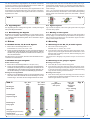
Um die verschiedenen Signaloptiken der Vorbilder nachbilden
zu können, besitzen manche Modellsignale mehrere LEDs der
gleichen Farbe und mit gleicher Markierung.
Der Abb. 1 können Sie die Zuordnung der Signal-LEDs zu den
Anschlüssen der Steuermodule bzw. der Decoder entnehmen.
Viele weitere Informationen über Signale finden Sie im Viessmann
Signalbuch, Art. 5299.
Some signals need more than one LED with the same colour to ge-
nerate specific signal aspects (e. g. departure signal with distant si-
gnal at the same mast). These signals have different cables with the
same markings.
In fig. 1 you can see the allocation of the signal LEDs to the outputs of
the control modules resp. the decoders. For more information regarding
signals please see Viessmann signal book, item 5299 – German
language.
3.2 Signalbegriffe
Die Signalbegriffe der Lichtsignale zeigt Abb. 2. Nicht jedes Signal
kann jeden Begriff darstellen.
3.3 Bezeichnung der Signale
Beigelegt ist eine Tafel mit Klebebildern (nur bei Signalen mit R-
Tafel) zur frei wählbaren Bezeichnung der Signale. Informationen
zur vorbildgerechten Beschriftung finden Sie im Viessmann Signal-
buch Art. 5299.
4. Einbau
4.1 Einbau der H0, TT, N und Z Signale
1. Bohren Sie an der Montagestelle ein Loch.
Durchmesser: H0, TT: 5,5 mm / N, Z: 4 mm.
2. Führen Sie das Anschlusskabel von oben durch das Montageloch
und stecken Sie dann das Signal mit dem Steckfuß hinein. Falls der
Steckfuß nicht genügend Halt findet, schieben Sie den Haltering von
unten auf den Steckfuß.
Das Signal muss nun fest sitzen, lässt sich aber bei Bedarf leicht he-
rausziehen und demontieren.
4.2 Einbau der Spur 0 Signale
Einbau auf der Anlage
1. Bohren Sie an der Montagestelle ein Loch (Ø 2,5 mm).
2. Führen Sie die Anschlusskabel von oben durch das Montageloch.
Schrauben Sie das Signal mit den beiliegenden Schrauben an der
Anlagenplatte fest. Falls das Signal nicht genügend Halt findet, dre-
hen Sie die Halteringe von unten auf die Besfestigungsschrauben.
Montage an der Teppichbahn
1. Platzieren Sie den Befestigungsclip an der Montagestelle neben
dem Gleis, indem Sie die Seite mit den Einkerbungen unter die
Schienen legen. So haben Sie den richtigen Abstand zum Gleis.
3.2 Signal aspects
Fig. 2 shows the aspects of the colour light signals. Not every signal
can show every aspect.
3.3 Marking of the signals
Adhesive signs are supplied with the signal (only with signals with R
board). Simply cut out the desired sign and attach it to the signal box
after removing the protective foil. The Viessmann signal book item
5299 provides helpful information.
4. Mounting
4.1 Mounting of the H0, TT, N and Z signals
1. Drill a hole at the mounting place.
Diameter: H0, TT: 5.5 mm / N, Z: 4 mm.
2. First insert the connection cable from above through the mount-
ing hole. Then put the signal with the base socket inside. In case
the base does not fit firmly in the hole, slide the holding ring onto
the base from below.
The signal has to fit tightly in its position but you can unmount it
easily.
4.2 Mounting of the gauge 0 signals
Mounting on the layout
1. Drill a hole (Ø 2.5 mm) at the mounting place.
2. First insert the connection cable from above through the mount-
ing hole. Screw the signal to the plate using the enclosed screws.
In case the signal does not fit firmly in the hole, slide the holding
rings onto the mounting screws from below.
Mounting on the carpet
1. Place the mounting clip at the mounting point next to the track
by placing the part with the indentations under the rails. Now you
have the right distance to the track.

Modellbauartikel, kein Spielzeug! Nicht geeignet für
Kinder unter 14 Jahren! Anleitung aufbewahren!
Model building item, not a toy! Not suitable for children
under the age of 14 years! Keep these instructions!
Ce n’est pas un jouet! Ne convient pas aux enfants de moi-
ns de 14 ans! Conservez cette notice d’instructions!
Não é um brinquedo! Não aconselhável para menores de
14 anos! Conservar o manual de instruções!
Modelbouwartikel, geen speelgoed! Niet geschikt voor
kinderen onder 14 jaar! Gebruiksaanwijzing bewaren!
Articolo di modellismo, non è un giocattolo! Non adatto
a bambini al di sotto dei 14 anni! Conservare istruzioni per
l’uso!
Artículo para modelismo ¡No es un juguete! No
recomendado para menores de 14 años! Conserva las
instrucciones de servicio!
DE
EN
FR
NL
IT
ES
PT
Made in Europe
Viessmann
Modelltec
hnik GmbH
Bahnhofstraße 2a
D - 35116 Hatzfeld-Reddighausen
+49 6452 9340-0
www.viessmann-modell.de
4
Fig. 3
viessmann 5550
Universal Ein-Aus-Umschalter
grün /
schwarz / black
gelb
4011
z. B. / e. g. 5200
rot /
diode
yellow
green
red
z. B. / e. g. 5550
Diode
Sekundär
0-10-16 V~
16 V
Primär
230 V~
Gefertigt nach
VDE 0570
EN 61558
Lichttransformator
5200
Nur für trockene Räume
Primär 230 V 50 - 60 Hz
Sekundär max. 3,25 A52 VA
ta 25°CIP 40
10 V
0 V
Abb. 3
Sekundär
0-10-16 V~
16 V
Primär
230 V~
Gefertigt nach
VDE 0570
EN 61558
Lichttransformator
5200
Nur für trockene Räume
Primär 230 V 50 - 60 Hz
Sekundär max. 3,25 A52 VA
ta 25°CIP 40
10 V
0 V
viessmann
Steuermodul für
Licht-Blocksignal
rt gn
Vorsignal -
Steuerung
zum Gleis
bn ge
16 V ~
5221
Universal Tasten - Stellpult
5547
Viessmann
rot / red
2 x schwarz / black
gelb / yellow
z. B.
5200
z. B.
5547
grün / green
blau / blue
braun / brown
/ e. g.
/ e. g.
diode
Diode
Fig. 4Abb. 4
Änderungen vorbehalten. Keine Haftung für Druckfehler und Irrtümer.
Die aktuelle Version der Anleitung finden Sie auf der Viessmann Homepage un-
ter der Artikelnummer.
Subject to change without prior notice. No liability for mistakes and printing errors.
You will find the latest version of the manual on the Viessmann website using
the item-No.
Entsorgen Sie dieses Produkt nicht über den (unsortierten) Hausmüll,
sondern führen Sie es der Wiederverwertung zu.
Do not dispose of this product through (unsorted) domestic waste, supply it
to recycling instead.
4010, 4011, 4012, 4013, 4014, 4015, 4016, 4030, 4410, 4411, 4412, 4413, 4414, 4415, 4416, 4811, 4910, 4911, 4912, 4913, 4915,
4916, 9011, 9012, 9013
2. Schieben Sie den Fuß des Signals in die vorgesehene Vorrich-
tung des Befestigungsclips.
3. Führen Sie die Kabel seitlich aus dem Clip
5. Anschluss
Vorsicht:
Widerstand und Diode an den Enden der Anschlussdrähte sind
für die Funktion erforderlich. Keinesfalls entfernen! Widerstände
nicht mit Isolationsmaterial umhüllen, da sonst keine ausreichen-
de Kühlung möglich ist!
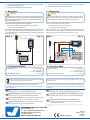
Sie können diese Signale flexibel anschließen:
- Direkt per Schalter an einen Modellbahntrafo (Abb. 3).
- An ein Viessmann Steuermodul.
Wir empfehlen die Verwendung eines Steuermoduls (z. B. Art. 5210
oder 5220 – 5224). Dann verfügt Ihr Signal über weichen Lichtwech-
sel, Zugbeeinflussung, Vorsignalsteuerung und einige Funktionen
mehr (z. B. Abb. 4).
2. Slide the signal foot into the intended device of the mounting clip.
3. Slide the cables sidewards out of the clip.
5. Connection
Caution:
Resistor and diode at the cables are needed for proper function.
Never cut them off! Never cover resistor or diode with insulation ma-
terial, because they have to be cooled by surrounding air!
You can connect the signals very flexibly:
- Via switch directly to a transformer (fig. 3).
- To a Viessmann control module.
We recommend to use a control module (e. g. items 5210 or 5220 –
5224), which offers more features and flexibility, smooth change of
the lights, train control, distant signal control (e. g. fig. 4).
6. Technical data
Operating voltage: 10 – 16 V AC ~
14 – 24 V DC =
13 – 24 V digital signal
Operating current (each LED): ca. 10 mA
6. Technische Daten
Betriebsspannung: 10 – 16 V AC ~
14 – 24 V DC =
13 – 24 V Digitalsignal
Stromaufnahme (je LED): ca. 10 mA
98106
Stand 13/sw
12/2022
Ho/Kf
-
 1
1
-
 2
2
-
 3
3
-
 4
4


