Meccanica Fadini Elpro 12 EVO Instructions Manual
- Typ
- Instructions Manual

I
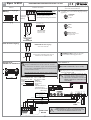
Programmatore a microprocessore
per apricancello scorrevole NYOTA 115 EVO pag. 2-3-4-5-6-7-8
Elpro 12 EVO
GB
F
D
I
- FUNZIONE PASSO-PASSO
- UOMO PRESENTE
- FRENO ELETTRONICO
- AUTOMATICO O SEMIAUTOMATICO
- RALLENTAMENTI PROGRAMMABILI
- PREDISPOSIZIONE PER OROLOGIO ESTERNO
- PREDISPOSIZIONE PER MASTER / SLAVE
- INVERSIONE AGLI OSTACOLI TRAMITE ENCODER
GB
F
D
Via Mantova, 177/A - 37053 Cerea (VR) Italy
Ph +39 0442 330422 Fax +39 0442 331054
info@fadini.net www.fadini.net
Dis. N.
7876
Mikroprozessorsteuerung
für Schiebetore NYOTA 115 EVO Seiten 23-24-25-26-27-28-29
- SCHRITT-IMPULS-FUNKTION
- TOTMANN-BEDIENUNG
- ELEKTROBREMSE
- AUTOMATISCH ODER HALBAUTOMATISCH
- PROGRAMMIERBARE ABBREMSUNGEN
- VORBEREITUNG FÜR EXTERNE UHR
- VORBEREITUNG FÜR MASTER / SLAVE
- LAUFUMKEHR BEI HINDERNIS DURCH ENCODER
- FONCTION PAS-PAS
- HOMME MORT
- FREIN ELECTRONIQUE
- AUTOMATIQUE OU SEMI-AUTOMATIQUE
- RALENTISSEMENT PROGRAMMABLE
- PREPARATION POUR HORLOGE EXTERNE
- PREPARATION POUR MASTER / SLAVE
- INVERSION DE MARCHE EN CAS D’OBSTACLE PAR ENCODEUR
Programmateur à microprocesseur
pour automatisme coulissant NYOTA 115 EVO pages 16-17-18-19-20-21-22
Control board with microprocessor
for NYOTA 115 EVO sliding gate operator pages 9-10-11-12-13-14-15
- STEP BY STEP OPERATIONS
- DEADMAN CONTROL
- ELECTRONIC BRAKE
- AUTOMATIC OR SEMIAUTOMATIC
- PROGRAMMABLE SLOWDOWNS
- PRESET FOR EXTERNAL TIME CLOCK
- PRESET FOR MASTER / SLAVE CONTROL
- REVERSING ON OBSTACLE DETECTION BY ENCODER

PROGRAMMATORE ELETTRONICO PER NYOTA 115 EVO
Elpro 12 EVO
I
Meccanica Fadini s.n.c.
Direttore Responsabile
DICHIARAZIONE DI CONFORMITÀ CE del costruttore:
Meccanica Fadini snc (Via Mantova, 177/A - 37053 Cerea - VR - Italy) dichiara sotto la propria responsabilità che Elpro 12 EVO è conforme alla direttiva
macchine 2006/42/CE, inoltre: viene commercializzato per essere installato in un "impianto automatizzato", con accessori e componenti originali
indicati dalla Ditta Costruttrice. La ditta costruttrice non si assume responsabilità circa l'uso improprio del prodotto. Il prodotto risulta conforme alle
seguenti normative speciche: Direttiva Bassa Tensione 2014/35/UE, Direttiva Compatibilità Elettromagnetica 2014/30/UE. Al ne di certicare il
prodotto il Costruttore dichiara sotto la propria responsabilità il rispetto della NORMATIVA DI PRODOTTO EN 13241-1.
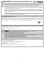
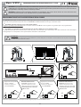
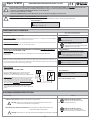
Descrizione generale: il programmatore elettronico Elpro 12 EVO è stato realizzato come soluzione per la gestione dell’apricancello scorrevole
Nyota 115 EVO (compresi modelli precedenti), con programmazione ad autoapprendimento delle varie fasi di movimento del cancello, ingresso per
encoder, freno elettronico e rallentamento in apertura e chiusura.
Alimentazione: 230 V ±10% 50 Hz monofase.
NEL CASO DI MANCATO FUNZIONAMENTO:
- Accertarsi che l'alimentazione al programmatore elettronico sia 230 V ±10% 50 Hz.
- Accertarsi che l'alimentazione al motore elettrico sia 230 V ±10% 50 Hz.
- Per distanze superiori ai 50 metri aumentare la sezione dei li.
- Controllare i fusibili.
- Controllare tutti i contatti chiusi del programmatore.
- Controllare che non ci sia una caduta di tensione tra programmatore e motore elettrico.
Attenzione: l’installazione di questo programmatore elettronico richiede una specica conoscenza tecnica e deve essere
eseguita da persone professionalmente qualicate e abilitate secondo le normative di sicurezza vigenti. È importante leggere e
seguire attentamente le istruzioni per evitare un errato uso e/o installazione del programmatore elettronico stesso.
Il programmatore elettronico Elpro 12 EVO è stato concepito e realizzato per la gestione dell’apricancello scorrevole
elettromeccanico NYOTA 115 EVO (compresi modelli precedenti). Ogni altro uso o utilizzo diverso da quanto specicato in
questo libretto di istruzione è da considerarsi vietato.
Meccanica Fadini declina ogni responsabilità per i danni derivanti a cose o persone dovuti all’eventuale errata installazione o
alla non messa a norma dell’impianto secondo le vigenti leggi; si impone l’applicazione della direttiva macchine 2006/42/CE.
Tutte le operazioni di manutenzione o verica dello stato del prodotto devono essere eettuate da personale qualicato e
professionalmente abilitato.
Prima di eettuare qualsiasi intervento sulla scheda, togliere l'alimentazione elettrica di rete. Si raccomanda inoltre di prendere
visione del libretto Normative di Sicurezza che Meccanica Fadini mette a disposizione. La ditta costruttrice non si assume
responsabilità circa l'uso improprio del programmatore elettronico.
!
!
IMPORTANTE:
- Il programmatore deve essere installato in un luogo protetto e asciutto con la propria scatola di protezione.
- Accertarsi che l’alimentazione al programmatore elettronico sia 230 V ±10%.
- Accertarsi che l’alimentazione al motore elettrico sia 230 V ±10%.
- Per distanze superiori ai 50 metri aumentare la sezione dei li.
- Applicare un interruttore magneto-termico dierenziale del tipo 0,03 A ad alta sensibilità all'alimentazione del programmatore.
- Per alimentazione, motore elettrico e lampeggiante usare li di sezione da 1,5 mm² no a 50 m di distanza.
- Per necorsa, fotocellule, pulsantiere e accessori usare cavi con li da 1 mm².
- Se non si usano le fotocellule eseguire un ponte tra i morsetti 1 e 2.
- Se non si usa nessun pulsante di stop eseguire un ponte tra i morsetti 3 e 6.
N.B.: per applicazioni quali accensioni luci, telecamere, ecc. utilizzare relè statici per non creare disturbi al microprocessore.
2

PROGRAMMATORE ELETTRONICO PER NYOTA 115 EVO
Elpro 12 EVO
I
3
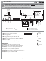
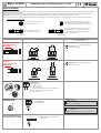
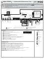
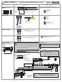
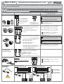
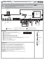
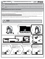
LED DI DIAGNOSTICA
L1 (verde acceso) = Fotocellule, si spegne ad ostacolo presente
L4 (rosso spento) = Apre, si illumina ad impulso del comando di apertura
L5 (rosso spento) = Chiude, si illumina ad impulso del comando di chiusura
L6 (verde acceso) = Blocco, si spegne ad impulso del comando di stop
L7 (rosso spento) = Radio, si illumina ad ogni impulso dal trasmettitore
L8 (rosso spento) = Finecorsa chiude, spento a cancello chiuso
L10 (rosso spento) = Finecorsa apre, spento a cancello aperto
L30 (rosso spento) = Pedonale, si illumina ad ogni comando pedonale
L31 (verde acceso) = Costa o fotocellula a protezione apertura, nessun ostacolo presente
L32 (verde acceso) = Costa a protezione chiusura, nessun ostacolo presente
L34 (verde acceso) = Ingresso del 2° Nyota 115 EVO
POWER (verde acceso) = Presenza tensione di rete 230 V e integrità fusibili F1, F2, F3, F4
DIP-SWITCH
1 = ON Fotocellula ferma in apertura
2 = ON Radio non inverte (e non blocca) in apertura
3 = ON Chiude in automatico
4 = ON Prelampeggio attivo
5 = ON Radio passo-passo con blocco intermedio
6 = ON Servizio a uomo presente (Dip 4 = OFF e Dip 3 = OFF)
7 = ON Lampeggiatore spento in pausa
8 = ON In apertura e in pausa richiude dopo passaggio fotocellula
9 = ON Elimina rallentamenti e lettura encoder (sostituisce ELPRO 12 PLUS)
10 = OFF Libero, da denire
11 = OFF Nyota 115 (1,0 CV), ON Nyota 115 (0,5 CV)
12 = ON Attiva funzione scheda secondaria (modalità slave)
ON
OFF
123456789101112
DIP-SWITCH
1234567891011 12 13 14 15
fotocellule
chiusura
contatto radio
comune
apre
chiude
stop
spia 24 V max 3 W
uscita 24 Vac (carico max:
n° 1 radio ricevente
n° 3 coppie fotocellule)
NC
L1 L4
L5 L6 L7 L8 L10
comune
A B
SETUP
EDGE
Power
Fc.A.
Fc.C.
contatto di
sicurezza
NC
pulsante per la programmazione
LP
ENC
ON
OFF
123456789101112
-
+
-
+
-
+
-
+
TEMPO DI PAUSA
2 - 128 s
PEDONALE
2 - 30 s
TRIMMER FRENO
ELETTRONICO
TRIMMER FORZA
costa apertura
comune
costa chiusura
8,2 kΩ o NC
8,2 kΩ o NC
NC
aux 2° NYOTA 115
pedonale
30 31 32 33 34
AP
CH
C
Uscita per 2ª
anta scorrevole
ELPRO 12 EVO
Elpro 12 EVO
L30 L31 L32L34
TRASFORMATORE
Supporto per scheda
radio da innesto
Encoder
alimentazione
MOTORE ELETTRICO
M1
uscita 230 Vac per
lampeggiante max 25 W
alimentazione scheda
MONOFASE
230 V ±10% 50/60 Hz
comune
NEUTRO
FASE
16 17 18 19 20 21 22
lampada di cortesia
230 V max 100 W
condensatore
F1=6,3 A linea
F2=6,3 A linea
F3=630 mA trasformatore
F4=2 A bassa
tensione 24 V
led rosso, deve essere sempre spento, si
accende in presenza di un contatto o di un
comando
led verde, deve essere
sempre acceso
led rosso lampeggiante: programmatore in
fase di programmazione, in attesa di un
impulso con pulsante di programmazione
23 24 25 26
27 28 29
Simbologia
Contatto NC
Contatto NA
Led acceso
Led spento
Spia o lampada
Lampeggiatore
Contatto resistivo
8,2 k
Ω
o NC
!
Per utilizzare Elpro 12 EVO in modalità compatibilità con Elpro 12 PLUS per NYOTA 115 vecchia serie quindi senza encoder, freno
elettronico, rallentamento e inversione all’ostacolo eseguire le seguenti impostazioni:
- settare al minimo il trimmer del freno elettronico
- impostare in ON il dip-switch n° 9
- settare al massimo il trimmer della forza in quanto verrà utilizzata la frizione meccanica.

PROGRAMMATORE ELETTRONICO PER NYOTA 115 EVO
Elpro 12 EVO
I
4
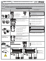
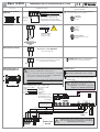
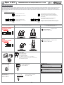
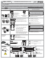
Tutti i possibili collegamenti ai morsetti del programmatore sono illustrati anche nei fogli d’istruzione dei singoli
accessori.
ATTENZIONE: L’UTILIZZO DI ACCESSORI NON FADINI PUÒ DANNEGGIARE LA SCHEDA. UTILIZZARE SEMPRE CONTATTI
PULITI PER GLI INGRESSI NA-NC. PONTICELLARE I CONTATTI NC NON UTILIZZATI.
!
!
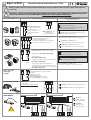
comune
comune
apre
chiude
stop
contatto
radio
Contatto radio:
Uscita spia di
segnalazione
da 24 V - max 3 W:
Selettore a chiave:
Fotocellule:
Accessorio Collegamenti elettrici
Dip-switch e segnalazione LED
delle varie funzioni
Tutti i contatti NC degli
accessori di sicurezza quali
fotocellule (ricevitori)
devono essere collegati in
serie ai morsetti 1 e 2
NC
NC
Uscita 24 Vac carico max:
n° 1 radio ricevente
n° 3 coppie fotocellule
12 13
1
DIP-SWITCH N° 1:
ON: ferma in apertura e inverte in chiusura a
ostacolo rimosso
OFF: non ferma in apertura e inverte in chiusura in
presenza di ostacolo
L1 verde acceso = nessun ostacolo presente, si
spegne ad ostacolo presente
F
A D I N I
1
2
3
4
5
6
7
8
9
A
B
STOP
Contatti NA e NC da collegare ai rispettivi
morsetti dei selettori o pulsantiere.
Tutte le possibili congurazioni sono allegate
ai rispettivi accessori di comando
L4 rosso spento = nessun contatto APRE,
si accende ad ogni impulso di apertura
L5 rosso spento = nessun contatto CHIUDE,
si accende ad ogni impulso di chiusura
L6 verde acceso = contatto di STOP chiuso,
si spegne ad ogni impulso di stop
Collegando un qualsiasi contatto NA tra i due
morsetti si può ottenere ad ogni impulso:
- Solo apertura: Dip 2=ON e Dip 5=OFF
- Inversione di marcia ad ogni impulso
Dip 2=OFF e Dip 5=OFF
- Passo Passo: Apre-Stop-Chiude-Stop
Dip 2=OFF e Dip 5=ON
- In fase di apertura non accetta nessun comando.
In pausa e in chiusura ad ogni comando esegue
lo stop con inversione di marcia:
Dip 2=ON e Dip 5=ON
1 2
3 4 5 6
3 7
ON: in apertura non inverte e non blocca
OFF: in apertura blocca e inverte sempre
2
ON: passo passo con blocco intermedio
OFF: inverte il movimento ad ogni impulso radio
5
DIP-SWITCH N° 2 e N° 5:
L7 rosso spento = nessun contatto RADIO,
si accende ad ogni impulso del contatto radio
comune
3 11
Uscita 24 V max 3 W per una eventuale lampada di
segnalazione dello stato dell'automazione:
Spia accesa = cancello aperto
Spia spenta = cancello chiuso
Lampeggia 0,5 s (veloce) = movimento di chiusura
Lampeggia 1 s (normale) = movimento di apertura
Finecorsa classici NC:
L8 rosso acceso = si spegne a Fc chiusura
L10 rosso acceso = si spegne a Fc apertura
8 9 10
IMPORTANTE:
Utilizzare necorsa normalmente chiusi
comune
necorsa di apertura
necorsa di chiusura
Finecorsa a
EFFETTO HALL:
!
marrone
verde
L8 rosso acceso
si spegne a Fc chiusura
L10 rosso acceso
si spegne a Fc apertura
12 13
8 9 10
nero
blu
12 13
8 9 10
INSTALLAZIONE A DESTRA INSTALLAZIONE A SINISTRA
f.c.c.
f.c.a.
f.c.c.
f.c.a.
marrone
verde
nero
blu

PROGRAMMATORE ELETTRONICO PER NYOTA 115 EVO
Elpro 12 EVO
I
8,2 k
Ω
5
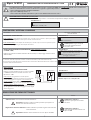
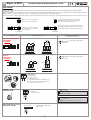
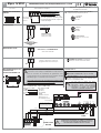
COSTE DI SICUREZZA
I due ingressi previsti per la gestione dei bordi sensibili, sono separati per la fase di apertura e la fase di chiusura e vengono riconosciuti dalla scheda Elpro 12 EVO
durante la fase di programmazione.
Grazie alla presenza di un circuito a microcontrollore dedicato e separato a bordo della scheda, viene continuamente monitorata l’eettiva integrità e perfetta
funzionalità delle coste di sicurezza. Ogni eventuale guasto o perdita di ecienza verrà segnalato tramite il lampeggio dei led L31 e L32.
In caso di ostacolo rilevato a seguito dell’intervento delle coste di sicurezza (o fotocellula in apertura), il cancello inverte per un breve tratto liberando l’ostacolo.
Ingresso fotocellule e
coste di sicurezza
in apertura
Ingresso
coste di sicurezza
in chiusura
In parallelo se
coste resistive 8,2 kΩ
31 32 33 32 33
8,2 kΩ
31
L31 verde acceso =
quando interviene la
costa il led si spegne
In serie se
coste meccaniche NC
In serie se
coste meccaniche NC
32 33
In parallelo se
coste resistive 8,2 k
Ω
32 33
L32 verde acceso =
quando interviene la
costa il led si spegne
Selezione tipo di funzionamento:
A B
Inverte in apertura e in chiusura
per un breve tratto di corsa.
Inverte in apertura e in chiusura
per un tratto doppio di corsa.
Il cancello dopo aver liberato l’ostacolo a seguito
dell’intervento della costa, chiude in automatico
(se impostata la funzione di chiusura in automatico).
Il cancello dopo aver liberato l'ostacolo a seguito
dell'intervento della costa, rimane fermo no a
nuovo comando (anche se impostata la funzione
di chiusura in automatico).
(A ponticellato) (B ponticellato)
A B
A B
A B
Uscita 24 Vac
carico max 500 mA:
n° 1 radio ricevente
n° 3 coppie fotocellule
n° 1 led Chis 37/Chis-E 37 oppure schedina DGT 61.
Tutte le istruzioni sono allegate ai rispettivi
accessori di comando
Uscita 24 V - max 500 mA:
VIX 53
12 13
Lampeggiatore
230 V max 25W
4
DIP-SWITCH N° 4:
ON: prelampeggio
OFF: senza prelampeggio
8
DIP-SWITCH N° 8:
ON: lampeggiatore disattivato durante la pausa
in automatico
OFF: lampeggia durante la pausa in automatico
LAMPEGGIATORE
230 V - 25 W max
19 20
l'a
p
ric
a
n
ce
llo
Uscita relè per lampada
di cortesia 230 V - 100 W
23 24 25 26
Uscita lampada di cortesia 230 V
max 100 W
Accessorio Collegamenti elettrici
Dip-switch e segnalazione LED
delle varie funzioni

PROGRAMMATORE ELETTRONICO PER NYOTA 115 EVO
Elpro 12 EVO
I
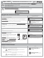
Alimentazione
MOTORE ELETTRICO
MONOFASE
230 V
M
comune
32 33
6
Ingresso per apertura
pedonale
Ingresso per
l’apertura
pedonale
comune
30 31
L30 rosso spento = nessun contatto PEDONALE,
si accende ad ogni impulso pedonale
Uscita motore
1816 17
23 24 25 26
CONDENSATORE
30 μF per 0,5 CV
30 μF per 1,0 CV
-
+
APERTURA
PEDONALE
2 - 30 s
Si consiglia l'uso dell'apertura pedonale
con Dip N° 3=ON per la richiusura
automatica).
La funzione "apertura pedonale" non è
attiva durante il primo ciclo di
funzionamento successivo ad una
mancanza di tensione di alimentazione.
Alimentazione scheda
Alimentazione scheda MONOFASE
230 V ±10% 50/60 Hz
21 22
FASE
NEUTRO
TEMPO DI
PAUSA
2 - 128 s
-
+
Contatto di sicurezza
Finchè non viene eseguito questo contatto il
programmatore non funziona
14 15
NC
POWER verde acceso = si spegne quando
viene rilasciato il contatto di sicurezza
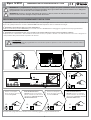
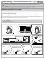
Collegamenti per n° 2
scorrevoli NYOTA 115
Master Slave
n° 4x1
È importante determinare Elpro 12 EVO MASTER che comanda e
controlla Elpro 12 EVO SLAVE con il Dip-switch 12.
Tutti gli accessori di comando, di segnalazione e di sicurezza
devono essere collegati ai morsetti di Elpro 12 EVO MASTER, il
quale gestisce e comanda tutto l’impianto.
Se le due ante non sono lunghe uguali, installare Elpro 12 EVO
Master sull’anta più lunga.
12
DIP-SWITCH N° 12:
ON: ELPRO 12 EVO SLAVE (2° Nyota 115 EVO)
OFF: ELPRO 12 EVO MASTER (1° Nyota 115 EVO)
L34 verde acceso = in entrambi i programmatori a
conferma della corretta comunicazione tra i due
ELPRO 12 EVO
PROGRAMMARE SEPARATAMENTE I NYOTA 115 MASTER E
SLAVE UNA VOLTA ESEGUITI I COLLEGAMENTI E POSIZIONATI
CORRETTAMENTE I DIP-SWITCH
AP
CH
C
Uscita per 2ª
anta scorrevole
30 31 32 33 34
Master
1 2 3 4 5 6 7 8 9 10
comune
apre
chiude
stop
L1 L4 L5 L6 L7 L8 L10
comune
Fc.A.
Fc.C.
ON
OFF
1 2 3 4 5 6 7 8 9 10 11 12
-
+
-
+
-
+
-
+
30 31 32 33 34
AP
CH
C
L30 L31 L32L33
Encoder
Slave
ELPRO 12 EVO
MASTER
27 28 29
27 28 29
ELPRO 12 EVO
SLAVE
29 3
33
È necessario un cavo
4 x 0,5 mm
2
per il
collegamento tra i due
programmatori ELPRO 12 EVO
Eseguire i seguenti collegamenti:
Elpro 12 EVO MASTER Elpro 12 EVO SLAVE
Dip-switch 12=OFF: Dip-switch 12=ON:
27 (AP) 4 (apre)
28 (CH) 5 (chiude)
29-33 (C) 3 (comune)
34 28 (CH)
29 ponticellato con 33
1 ponticellato con 2
3 (comune) ponticellato
con 6 (stop)
TRIMMER FORZA
regola la forza esercitata sul
cancello
-
+
Si rimanda alle pagine precedenti per la
composizione dei Dip-switch relativi ai
singoli accessori e funzioni.
Dip-switch e accessori da impostare e
collegare solo sull’ELPRO 12 EVO Master.
Accessorio Collegamenti elettrici
Dip-switch e segnalazione LED
delle varie funzioni
!

PROGRAMMATORE ELETTRONICO PER NYOTA 115 EVO
Elpro 12 EVO
I
7
Descrizione
AUTOMATICO / SEMIAUTOMATICO:
Ciclo automatico: ad un impulso di comando apre, il cancello si apre, si ferma in pausa per il tempo
impostato sul trimmer pausa, scaduto il quale richiude automaticamente.
Ciclo semiautomatico: ad un impulso di comando apre, il cancello si apre e si blocca in posizione aperto.
Per chiudere il passaggio bisogna dare l'impulso di chiusura.
Trimmer pausa: si regola il tempo di
pausa nella modalità automatico
da 2 s no a 128 s
3
ON: chiude in automatico
OFF: semiautomatico
DIP-SWITCH N° 3:
DIP-SWITCH N° 8:
UOMO PRESENTE:
Si ottiene il comando di apertura e chiusura "ad azione mantenuta" (senza autoritenuta nei relè).
È richiesta la presenza dell'operatore durante tutto il movimento dell'automazione no al rilascio del
pulsante o della chiave del selettore.
6
ON: attiva funzione uomo presente
OFF: disattiva uomo presente
DIP-SWITCH N° 6:
3
DIP-SWITCH N° 3:
34
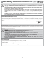
PARTY FUNCTION
APERTURA MEDIANTE OROLOGIO ESTERNO:
Collegare il contatto NA dell'orologio ai morsetti n° 4 APRE e
n° 3 COMUNE, attivando la richiusura automatica con il
Dip-switch n° 3=ON.
Funzionamento: programmare l'orario di apertura
sull'orologio, all'ora impostata il cancello si apre rimanendo
aperto (il lampeggiante si spegne), e non accetterà più
nessun comando (anche radio) sino allo scadere del tempo
impostato sull'orologio, allo scadere del quale, dopo il tempo
di pausa, seguirà la chiusura automatica.
Durante la sosta a cancello aperto con comando "orologio" la
spia di segnalazione emette due lampeggi ravvicinati seguiti
da una lunga pausa.
-
+
RICHIUSURA AL PASSAGGIO SULLE FOTOCELLULE: in fase di apertura e in pausa
(con DIP N° 3=ON)
Funzione che permette la richiusura automatica del cancello dopo 3 s dal passaggio attraverso il fascio
delle fotocellule.
8
ON: richiusura automatica al passaggio sulla
coppia fotocellule dopo 3 secondi
OFF: nessuna richiusura automatica al
passaggio su fotocellule
NA
Orologio esterno
ON: chiude in automatico
IMPORTANTE:
utilizzare sempre e solo con Dip N° 3=ON
!
Per utilizzare Elpro 12 EVO in modalità compatibilità con Elpro 12 PLUS per NYOTA 115 vecchia serie quindi senza encoder, freno
elettronico, rallentamento e inversione all’ostacolo eseguire le seguenti impostazioni:
- settare al minimo il trimmer del freno elettronico
- impostare in ON il dip-switch n° 9
- settare al massimo trimmer della forza in quanto verrà utilizzata la frizione meccanica.
FUNZIONI PER L’APERTURA SCORREVOLE
comune
apre
Descrizione
REGOLAZIONE DEL FRENO ELETTRONICO
Trimmer
Trimmer freno elettronico:
impostare a 0 per Nyota 115 con freno
meccanico
-
+
Trimmer freno elettronico:
regola l’intensità del freno elettronico nei
Nyota 115 EVO
-
+
- Trimmer a zero: viene esclusa la frenatura elettronica.
Importante: impostare sempre in questa posizione per i Nyota 115
vecchia serie con freno meccanico.
!
0
- Regolazione del freno elettronico: tramite il trimmer è possibile regolare l’intensità del
freno elettronico.
Importante: utilizzare il freno elettronico solo con i Nyota 115 EVO
!
11
ON: Nyota 115 EVO 0,5 CV
OFF: Nyota 115 EVO 1,0 CV
DIP-SWITCH N° 11:
!
SELEZIONE NYOTA 115 EVO DA 1,0 CV O 0,5 CV
È fondamentale selezionare correttamente tramite il dip-switch n° 11 il modello corrispondente di Nyota 115 EVO:
Dip-switch e segnalazione LED
delle varie funzioni

PROGRAMMATORE ELETTRONICO PER NYOTA 115 EVO
Elpro 12 EVO
I
8
!
IMPORTANTE: la programmazione del Nyota 115 deve essere eseguita alla prima installazione. Anche in mancanza di
alimentazione di rete, la programmazione rimane memorizzata. Dopo ogni modica della posizione dei necorsa, è obbligatorio
riprogrammare la corsa del cancello con la medesima procedura.
IMPORTANTE: vericare la presenza delle battute di apertura e chiusura, mentre le stae dei necorsa di apertura e chiusura
devono essere ssate sulla cremagliera nelle posizioni di intervento.
!
PROGRAMMAZIONE E AUTOAPPRENDIMENTO DELLA CORSA
LP
1
a
operazione: sbloccare aprendo no alla sua battuta (oltre i 90°) la maniglia di sblocco con la chiave cifrata e rendere libero il cancello dal
Nyota 115, quindi posizionare il cancello a circa metà della sua corsa. Ripristinare il blocco chiudendo la maniglia.
2
a
operazione: apprendimento della corsa e dei rallentamenti.
Premere e mantenere premuto il Pulsante P per 5 secondi e rilasciare: il led LP inizierà a lampeggiare segnalando la fase di programmazione.
3
a
operazione: la programmazione può essere eseguita con il pulsante dedicato P oppure con il trasmettitore codicato.
È importante che ci siano tutte e due le battute di arresto del cancello, in apertura e chiusura e le stae dei necorsa meccanici o magnetici in
corrispondenza della posizione nale di apertura e di chiusura.
1 2 3 4 5 6 7 8 9 10 11 12 13 14 15
L1 L4 L5 L6 L7 L8 L10
A B
SETUP
EDGE
Power
LP
ENC
ON
OFF
1 2 3 4 5 6 7 8 9 10 11 12
-
+
-
+
-
+
-
+
30 31 32 33 34
AP
CH
C
Uscita per 2ª
anta scorrevole
ELPRO 12 EVO
Elpro 12 EVO
L30 L31 L32L33
Encoder
16 17 18 19 20 21 22
23 24 25 26
27 28 29
Premere con un impulso:
Nyota 115 inizierà a muovere
il cancello in apertura
Inizio del rallentamento in
apertura: premere con un impulso
quando si desidera che inizi la fase di
rallentamento e attendere che arrivi
alla lettura del necorsa
Premere con un impulso:
Nyota 115 inizierà a muovere
il cancello in chiusura
Inizio del rallentamento in
chiusura: premere con un impulso
quando si desidera che inizi la fase di
rallentamento e attendere che arrivi
alla lettura del necorsa
Al termine della programmazione attendere che il led LP lampeggi no a spegnersi denitivamente.
5 s
LP
LP LPLP LP
!
ATTENZIONE:
Nella prima manovra di programmazione il cancello deve partire in apertura. Se così non fosse invertire le fasi del motore e
controllare i necorsa.

ELECTRONIC CONTROL BOARD FOR NYOTA 115 EVO
Elpro 12 EVO
GB
Meccanica Fadini s.n.c.
Direttore Responsabile
CE DECLARATION OF CONFORMITY of the manufacturer:
Meccanica Fadini snc (Via Mantova, 177/A - 37053 Cerea - VR - Italy) declares under own responsibility that Elpro 12 EVO complies with the
2006/42/CE Machinery Directive, and also that it is sold to be installed in an “automatic system”, along with original accessories and components as
indicated by the manufacturing company. The manufacturer is not liable for possible incorrect use of the product. The product complies with the
following specic norms: Low Voltage Directive 2014/35/UE, Electromagnetic Compatibility Directive 2014/30/UE. In order to certify the product, the
Manufacturer declares under own responsibility the compliance with the EN 13241-1 PRODUCT NORMS.
General description: Elpro 12 EVO electronic board has been produced in order to provide an ideal solution to the control of the sliding gate
operator Nyota 115 EVO (including the previous versions), and incorporates self-learning programming of the gate cycle, encoder input, electronic
brake and slowdown in opening and closing phases.
Power supply: 230 V ±10% 50 Hz single-phase.
TROUBLE SHOOTING IN CASE OF FAILURE:
- Make sure that power supply to the electronic control board is 230 V ±10% 50 Hz.
- Make sure that power supply to the electric motor is 230 V ±10% 50 Hz.
- In case of distances wider than 50 meters, increase the wire section.
- Check the fuses.
- Check all the N.C. contacts in the control board.
- Make sure that no voltage drop is occurring between control board and electric motor.
Note well: the installation of this electronic control board requires a specic technical knowledge and must be carried out by
professionally qualied people and habilitated according to the safety norms in force. It is important that these instructions be
carefully read and followed to avoid that the electronic control board be used and/or installed in the wrong way.
Elpro 12 EVO has been designed and constructed to control NYOTA 115 EVO electromechanical operators for sliding gates
(including the previous versions of them). Any other use or application, dierent from that specied in this manual is strictly
prohibited.
Meccanica Fadini declines any responsibility for damage caused to properties or persons due to possible incorrect installations
or failure of the system to comply with the applicable regulations; it is compulsory that the machinery directive 2006/42/CE be
implemented. Maintenance or inspections to assess the product status must be carried out by qualied and professionally
trained technicians.
Before any servicing is made to the board, disconnect mains power supply. It is also recommended that the Safety Norms
manual be read, available from Meccanica Fadini on request. The manufacturing company does not take any liability for
improper use of the electronic control board.
!
!
IMPORTANT:
- The control board should be installed in a sheltered, dry place inside its own protection box.
- Make sure that power supply to the electronic control board is 230 V ±10%.
- Make sure that power supply to the electric motor is 230 V ±10%.
- In case of distances wider than 50 meters, increase the wire section.
- Fit the power supply to the control board with a 0,03 A high sensibility, magneto-thermal circuit breaker.
- For the power supply, electric motor and asher use 1,5 mm² section wires up to 50 m of distance.
- For the limit switches, photocells, command switches and accessories use 1 mm² section wires.
- If no photocells are used bridge terminals 1 and 2.
- If no stop button is used bridge terminals 3 and 6.
N.W.: for applications such as lights control, CCTV, etc. use solid state relays to prevent intereference with the microprocessor.
9

ELECTRONIC CONTROL BOARD FOR NYOTA 115 EVO
Elpro 12 EVO
GB
DIAGNOSTICS BY LEDs
L1 (green ON) = Photocells, switches to OFF when an obstacle is detected
L4 (red OFF) = Open, switches to ON when a command pulse to open is given
L5 (red OFF) = Close, switches to ON when a command pulse to close is given
L6 (green ON) = Stop, switches to OFF when a command pulse to stop is given
L7 (red OFF) = Radio, switches to ON when a transmitter button is pulsed
L8 (red OFF) = Limit switch close, OFF with gate in closed position
L10 (red OFF) = Limit switch open, OFF with gate in open position
L30 (red OFF) = Pedestrian, switches to ON whenever a pulse is given to the pedestrian command
L31 (green ON) = Safety edge or photocells in opening, no obstacle detected
L32 (green ON) = Safety edge in closing, no obstacle detected
L34 (green ON) = 2nd Nyota 115 EVO input
POWER (green ON) = Board under 230 V power supply and F1, F2, F3, F4 fuses intact
DIP-SWITCH
1 = ON Photocells stop gate in opening
2 = ON Radio does not reverse (and not stop gate) in opening
3 = ON Automatic closing
4 = ON Pre-ashing activated
5 = ON Radio step-by-step mode, stop in between
6 = ON Deadman control (Dip 4 = OFF and Dip 3 = OFF)
7 = ON Flasher o in dwell time
8 = ON Reclosing on photocells engagement during opening and dwell time
9 = ON Slowdowns and encoder disabled (to replace ELPRO 12 PLUS)
10 = OFF Blank, function to dene
11 = OFF Nyota 115 (1,0 HP), ON Nyota 115 (0,5 HP)
12 = ON Secondary board activated (slave mode)
ON
OFF
123456789101112
DIP-SWITCH
1234567891011 12 13 14 15
photocells
closing
radio contact
common
open
close
stop
pilot light 24 V max 3 W
24 Vac output ( max load:
n° 1 radio receiver
n° 3 pairs of photocells)
NC
L1 L4
L5 L6 L7 L8 L10
common
A B
SAFETY
EDGE
SETUP
Lsw.O.
Lsw.C.
safety
contact
NC
programming button
LP
ENC
ON
OFF
123456789101112
-
+
-
+
-
+
-
+
DWELL TIME
2 - 128 s
PEDESTRIAN
2 - 30 s
ELECTRONIC
BRAKE TRIMMER
TORQUE TRIMMER
openig safety edge
common
closing safety edge
8,2 kΩ or NC
8,2 kΩ or NC
NC
2nd NYOTA 115
pedestrians
30 31 32 33 34
AP
CH
C
Output for 2nd
sliding gate
ELPRO 12 EVO
Elpro 12 EVO
L30 L31 L32L34
TRANSFORMER
Plug-in card
support
Encoder
M1
230 Vac output for
asher max 25 W
board power supply
SINGLE-PHASE
230 V ±10% 50/60 Hz
common
NEUTRAL
LIVE
16 17 18 19 20 21 22
courtesy light
230 V max 100 W
capacitor
F1=6,3 A mains
F2=6,3 A mains
F3=630 mA transformer
F4=2 A low
voltage 24 V
red led, it must be always OFF, it goes ON
whenever a contact or a command are given
green led, it must be
always ON
asher red led: board on programming
phase, waiting for a pulse by the
programming button
23 24 25 26
27 28 29
Symbols
NC contact
NO contact
Led ON
Led OFF
Pilot light or lamp
Flasher
Resistive contact
8,2 k
Ω
or NC
!
In cases where Elpro 12 EVO is to be used in compatibility with Elpro 12 PLUS for NYOTA 115 old series ,therefore without encoder,
electronic brake, slowdown and reversing on obstacle impact, the following settings are required:
- set the electronic brake trimmer to the lowest
- set dip-switch no. 9 to ON
- set the torque trimmer to the highest as the mechanical clutch will be used.
10
ELECTRIC MOTOR
power supply
Power

ELECTRONIC CONTROL BOARD FOR NYOTA 115 EVO
Elpro 12 EVO
GB
All the possible connections to the control board terminals are also described in the instructions sheets of the respective
accessories.
NOTE WELL: THE INSTALLATION OF NON FADINI ORIGINAL ACCESSORIES MAY DAMAGE THE PC BOARD. MAKE ALWAYS
USE OF FREE CONTACTS FOR THE NO-NC INPUTS. BRIDGE ALL THE NC CONTACTS NOT IN USE.
!
!
common
common
open
close
stop
radio
contact
Radio contact:
Keyswitch:
Photocells:
Accessory Electrical connections
Dip-switch and LED indication
of the various functions
All the NC contacts of the
safety accessories such as
the photocells (the
receiver set) to be series
connected to terminals
1 and 2
NC
NC
24 Vac output max. load:
1 radio receiver
3 pairs of photocells
12 13
1
DIP-SWITCH N° 1:
ON: stop in opening and travel reversing in
closing on obstacle removal
OFF: no stop in opening and travel reversing in
closing on obstacle detection
L1 green on = no obstacle detected, it goes o
in case an obstacle interposes
FA D IN I
1
2
3
4
5
6
7
8
9
A
B
S
T
OP
NO and NC contacts to be connected to the
respective terminals in the key- or
button-operated switches.
All possible congurations are attached to
the respective command accessories.
L4 red o = no OPEN contact,
it goes on whenever a pulse to open is given
L5 red o = no CLOSE contact,
it goes on whenever a pulse to close is given
L6 green on = STOP contact closed ,
it goes o whenever a pulse to stop is given
By any NO connection to these two terminals the
following is performed, on each pulse given:
- Opening only: Dip 2=ON and Dip 5=OFF
- Travel reversing
Dip 2=OFF and Dip 5=OFF
- Step by Step operations: Open-Stop-Close-Stop
Dip 2=OFF and Dip 5=ON
- In opening no other command pulse is
accepted. On dwell time and in closing, by each
command pulse, stop and reverse are performed:
Dip 2=ON and Dip 5=ON
1 2
3 4 5 6
3 7
ON: no reversing and no stop in opening
OFF: always stop and reversing in opening
2
ON: step by step with stop in between
OFF: reversing on radio pulsing
5
DIP-SWITCHES N° 2 and 5:
L7 red o = no RADIO contact,
it goes on whenever a radio pulse is given
common
3 11
24 V max 3 W output for a light to indicate
gate status:
Light on = gate open
Light o = gate closed
Flashing 0,5 s (fast) = gate closing
Flashing 1 s (normal) = gate closing
Standard limit switch:
L8 red on = limit sw. closing, o on gate closed
L10 red on = limit sw. open, o on gate open
8 9 10
IMPORTANT:
Use normally closed limit switches
common
opening limit switch
closing limit switch
11
24 V - max 3 W
pilot light
output:
Limit switch
HALL EFFECT:
!
brown
green
12 13
8 9 10
black
blue
12 13
8 9 10
MOUNT ON THE RIGHT MOUNT ON THE LEFT
l.s.c.
l.s.o.
l.s.c.
l.s.o.
L8 red on
limit sw. closing,
o on gate closed
L10 red on
limit sw. open
o on gate open
brown
green
black
blue

ELECTRONIC CONTROL BOARD FOR NYOTA 115 EVO
Elpro 12 EVO
GB
8,2 k
Ω
SAFETY EDGES
The two inputs, dedicated to the control of the safety edges, are separated for the opening and closing phases and are recognized by Elpro 12 EVO during the
programming phase.
Thanks to the presence of a circuit with microcontroller, specically dedicated and separately tted on to the board, the integrity and correct functioning of the safety
edges are monitored all the time.All possible faults or loss of eciency are indicated by L31 and L32 LEDs ashing.
In case an obstacle is detected by the safety edges (or photocells in opening), gate travel is reversed for a short distance allowing the obstacle to be freed and removed.
Input for photocells and
safety edges
in opening
Input for
safety edges
in closing
In parallel in case of
resistive 8,2 kΩ edges
31 32 33 32 33
8,2 kΩ
31
L31 green on =
when edge is engaged the
led turns o
In series in case of
NC mechanical edges
In series in case of
NC mechanical edges
32 33
In parallel in case of
resistive 8,2 kΩ edges
32 33
L32 green on =
when edge is engaged the
led turns o
Selecting mode of functioning:
A B
Gate travel is reversed in opening
and closing for a short distance.
Gate travel is reversed in opening
and closing for twice as much the
previous distance.
Safety edge detects the obstacle, gate allows for
obstacle release and then closes automatically.
(if auto close mode has been pre-set).
Gate allows for obstacle release after safety edge has
been engaged, but stays still until a new command is
given. (Inspite auto close mode having been pre-set).
(A bridged) (B bridged)
A B
A B
A B
24 Vac output
max load 500 mA:
n° 1 radio receiver
n° 3 pairs of photocells
n° 1 led in Chis 37/Chis-E 37 or DGT 61 card.
Full instructions are enclosed along with the
respective command accessory.
24 V output - max 500 mA:
VIX 53
12 13
Flasher
230 V max 25W
4
DIP-SWITCH N° 4:
ON: pre-ashing
OFF: no pre-ashing
8
DIP-SWITCH N° 8:
ON: asher deactivated during dwell time in auto
close mode
OFF: ashes in dwell time, auto close mode
FLASHER
230 V - 25 W max
19 20
l'a
p
ric
a
n
ce
llo
Relay output for courtesy
light 230 V - 100 W
23 24 25 26
Courtesy light output 230 V
max 100 W
Accessory Electrical connections
Dip-switch and LED indication
of the various functions
12

ELECTRONIC CONTROL BOARD FOR NYOTA 115 EVO
Elpro 12 EVO
GB
Power supply
SINGLE-PHASE
230 V
ELECTRIC MOTOR
M
common
32 33
Input for pedestrian
opening
Input for
pedestrian
opening
common
30 31
L30 red o = no PEDESTRIAN contact, it goes on
whenever a pulse for pedestrian opening is given
Motor output
1816 17
23 24 25 26
CAPACITOR
20 μF for 0,5 HP
30 μF for 1,0 HP
-
+
PEDESTRIAN
OPENING
2 - 30 s
On pedestrian opening mode it is
recommended that Dip 3=ON for auto
close).
The “pedestrian opening” function is
not activated during the rst cycle
following a voltage cut o.
PCB power supply
SINGLE-PHASE power supply
230 V ±10% 50/60 Hz
21 22
LIVE
NEUTRAL
DWELL
TIME
2 - 128 s
-
+
Safety contact
As long as this connection is not made the
control board does not work
14 15
NC
POWER green on =
it goes o when the
safety contact is released
Connections for 2
NYOTA 115 sliding gate
operators
Master Slave
n° 4x1
It is important to establish which Elpro 12 EVO is the MASTER
commanding/controlling Elpro 12 EVO SLAVE by Dip-switch 12.
All the accessories for command, signalling and safety purposes
must be connected to Elpro 12 EVO MASTER, that controls and
commands the entire installation.
If the two gates are not equally large, install Elpro 12 EVO
Master on the larger one.
12
DIP-SWITCH N° 12:
ON: ELPRO 12 EVO SLAVE (2nd Nyota 115 EVO)
OFF: ELPRO 12 EVO MASTER (1st Nyota 115 EVO)
L34 green on = in both boards as a conrmation
of the correct communication between the two
ELPRO 12 EVOs
PROGRAM NYOTA 115 MASTER AND SLAVE SEPARATELY
ONCE THE CONNECTIONS ARE MADE AND THE
DIP-SWITCHES CORRECTLY ARRANGED
AP
CH
C
Output for 2nd
sliding gate
30 31 32 33 34
Master
1 2 3 4 5 6 7 8 9 10
common
open
close
stop
L1 L4 L5 L6 L7 L8 L10
common
Lsw.O
Lsw.C
ON
OFF
1 2 3 4 5 6 7 8 9 10 11 12
-
+
-
+
-
+
-
+
30 31 32 33 34
AP
CH
C
L30 L31 L32L33
Encoder
Slave
ELPRO 12 EVO
MASTER
27 28 29
27 28 29
ELPRO 12 EVO
SLAVE
29 3
33
A 4 x 0,5 mm
2
cable is
required for the connection
between the two
ELPRO 12 EVO control boards
The following connections are to be made:
Elpro 12 EVO MASTER Elpro 12 EVO SLAVE
Dip-switch 12=OFF: Dip-switch 12=ON:
27 (AP) 4 (open)
28 (CH) 5 (close)
29-33 (C) 3 (common)
34 28 (CH)
29 bridged with 33
1 bridged with 2
3 (common) bridged
with 6 (stop)
TORQUE TRIMMER
controls the force applied
to the gate
-
+
See the previous pages for the array of the
Dip-switches related to the individual
accessories and functions.
Dip-switches and accessories to be set
and connected only on ELPRO 12 EVO
Master.
Accessory Electrical connections
Dip-switch and LED indication
of the various functions
13
!

ELECTRONIC CONTROL BOARD FOR NYOTA 115 EVO
Elpro 12 EVO
GB
Description
AUTOMATIC / SEMIAUTOMATIC:
Automatic operation: on pulsing an open command, the gate opens, stays open untill dwell time expires
as set by the dwell trimmer, then closes automatically.
Semiautomatic operation: on pulsing an open command, the gate opens and stops in open position.
A close pulse is needed for the gate to close.
Dwell trimmer: dwell time is required to
be set when automatic mode is selected
2 s up to 128 s
3
ON: automatic closing
OFF: semiautomatic
DIP-SWITCH N° 3:
DIP-SWITCH N° 8:
DEADMAN CONTROL (hold-on-switched):
Open and close commands are performed “by holding a switch on” (no relay self-holding is involved)
therefore a phisical attendance is required to keep the gate running until either the button or key are
released.
6
ON: deadman control activated
OFF: deadman control deactivated
DIP-SWITCH N° 6:
3
DIP-SWITCH N° 3:
34
PARTY FUNCTION
OPENING BY EXTERNAL TIME CLOCK:
Connect the NO contact of the time clock to terminals 4
OPEN and 3 COMMON, set the board to auto closing by
Dip-Switch 3=ON.
How it works: set the clock to the required opening time. On
the pre-set time the gate is opened and held open (the
asher goes o), and no more commands (even by radio) are
accepted until the clock pre-set time expires. On expiring,
and after the pre-set dwell time, auto closing is performed.
During dwell time with gate in open position on “time clock”
command, the pilot light gives out two short ashes
followed by a longer pause.
-
+
RICLOSING ON PHOTOCELL ENGAGEMENT: in opening and dwell phases
(DIP-SWITCH N° 3=ON)
This function allows the gate to auto close after 3 s the photocell beam has been crossed.
8
ON: auto closing on photocell engagement
after 3 seconds
OFF: no auto closing on photocell
engagement
NO
External time clock
ON: auto closing
IMPORTANT:
always and only with Dip N° 3=ON
!
The following setting is required when Elpro 12 EVO is to be used in compatibility with Elpro 12 PLUS for NYOTA 115 old series and
therefore without encoder, electronic brake, slowdow and reversing on obstacle detection:
- set the electronic brake trimmer to the lowest
- set dip-switch 9 to ON
- set the torque trimmer to the highest as the mechanical clutch will be used.
FUNCTIONING ON SLIDING GATES
common
open
Description
ELECTRONIC BRAKE SETTING
Trimmer
Electronic brake trimmer:
set it to 0 for Nyota 115 with mechanical
brake
-
+
Electronic brake trimmer:
set it as required to control brake intensity
with Nyota 115 EVO
-
+
- Trimmer set to 0 : electronic brake deactivated.
Important: set it always to this position for Nyota 115 old series tted
with mechanical brake.
!
0
- Adjusting the electronic brake: it is possible to adjust brake intensity by the dedicated
trimmer
Important: use the electronic brake function only with Nyota 115 EVO
!
11
ON: Nyota 115 EVO 0,5 HP
OFF: Nyota 115 EVO 1,0 HP
DIP-SWITCH N° 11:
!
SELECTION OF NYOTA 115 EVO EITHER 1,0 HP OR 0,5 HP
It is fundamental that the required model of Nyota 115 EVO be properly selected by dip-switch 11:
Dip-switch and LED indication
of the various functions
14

ELECTRONIC CONTROL BOARD FOR NYOTA 115 EVO
Elpro 12 EVO
GB
!
IMPORTANT: Programming Nyota 115 must be carried out on the rst installation and is retained even in case of a voltage cut o.
Any time the position of the limit switches is varied, it is required that gate travel be programmed again in the same way.
IMPORTANT: make sure that gate stops are duly tted to the system in open and closed gate stop positions, whereas the open and
close limit switch striking plates are to be xed on to the gear rack in the engaging positions are required.
!
PROGRAMMING AND GATE TRAVEL SELF-LEARNING
LP
1
st
operation: by the coded key open the release handle until it stops (more than 90°). In this way Nyota 115 is disengaged from the gate. Pull gate
by hand to approximately half way of the total travel. Lock back the operator by closing the handle.
2
nd
operation: gate travel and slowdows learning.
Press and hold button P for 5 seconds then let it go: led LP will start ashing, so indicating that programming phase has started.
3
rd
operation: programming can be carried out either by pressing the dedicated P button, or remotely by the encoded transmitter.
It is most important that both gate stops, in open and close gate positions, be provided as well as the mechanical limit switch striking plates or the
magnetic ones in correspondence with the nal open and closed gate positions as required.
1 2 3 4 5 6 7 8 9 10 11 12 13 14 15
L1 L4 L5 L6 L7 L8 L10
A B
SETUP
EDGE
LP
ENC
ON
OFF
1 2 3 4 5 6 7 8 9 10 11 12
-
+
-
+
-
+
-
+
30 31 32 33 34
AP
CH
C
Output for 2nd
sliding gate
ELPRO 12 EVO
Elpro 12 EVO
L30 L31 L32L33
Encoder
16 17 18 19 20 21 22
23 24 25 26
27 28 29
Pulse once:
Nyota 115 will start
opening
Starting slowdown in
opening: give one pulse when it is
required that slowdown phase starts
and wait until limit switch reading
point is reached
Pulse once:
Nyota 115 will start
closing
Starting slowdown in
closing: give one pulse when it is
required that slowdown phase starts
and wait until limit switch reading
point is reached
At the end of the programming operations, wait for LP led to ash and then go o permanently.
5 s
LP
LP LPLP LP
!
NOTE WELL:
During the rst programming phase, the gate must start with the opening operation. Should it not, reverse motor phases and
check the limit switches.
15
Power

PROGRAMMATEUR ELECTRONIQUE POUR NYOTA 115 EVO
Elpro 12 EVO
F
Meccanica Fadini s.n.c.
Direttore Responsabile
DECLARATION DE CONFORMITE CE du constructeur:
Meccanica Fadini snc (Via Mantova, 177/A - 37053 Cerea - VR - Italy) déclare sous sa propre responsabilité que Elpro 12 EVO est conforme à la
directive machines 2006/42/CE, en outre: il est commercialisé pour être installé dans une "installation automatisée", avec les accessoires et les
composants originaux indiqués par l’Entreprise de Construction. L’entreprise de construction ne s’assume aucune responsabilité à propos de la
mauvaise utilisation du produit. Le produit est conforme aux normes suivantes: Directive Basse Tension 2014/35/UE, Directive Compatibilité
Electromagnétique 2014/30/UE. An de certier le produit le Constructeur déclare sous sa propre responsabilité le respect de la NORME DU PRODUIT
13241-1.
Description générale: le programmateur électronique Elpro 12 EVO a été réalisé pour la gestion de l’ouvre portail coulissant Nyota 115 EVO (y
compris les modèles précédents), avec programmation à auto-apprentissage des diérentes phases de mouvement du portail, entrée par encodeur,
frein électronique et ralentissement à l’ouverture et à la fermeture.
Alimentation: 230 V ±10% 50 Hz monophasée.
EN CAS DE DEFAILLANCE:
- S’assurer que l'alimentation sur le programmateur électronique soit 230 V ±10% 50 Hz.
- S’assurer que l'alimentation sur le moteur électrique soit 230 V ±10% 50 Hz.
- Pour distances supérieures à 50 mètres augmentez la section des ls.
- Contrôlez les fusibles.
- Contrôlez tous les contacts fermés du programmateur.
- Contrôlez qu’il n’y ait pas une chute de tension entre le programmateur et le moteur électrique.
!
!
IMPORTANT:
- Le programmateur doit être installé dans un lieu protegé et abrité dans sa boîte de protection.
- S’assurer que l’alimentation sur le programmateur électronique soit 230 V ±10%.
- S’assurer que l’alimentation sur le moteur électrique soit 230 V ±10%.
- Pour distances supérieures à 50 mètres augmentez la section des ls.
- Appliquez un interrupteur magnéto-thermique diérentiel du type 0,03 A à haute sensibilité à l'alimentation du
programmateur.
- Pour l’ alimentation, le moteur électrique et la lampe clignotante utilisez des ls de section de 1,5 mm² jusqu’à 50 m de distance.
- Pour ns de course, photocellules, boîtes boutons poussoirs et accessoires utilisez câbles avec ls de 1 mm².
- Si vous n’utilisez pas les photocellules, faites une liaison entre les bornes 1 et 2.
- Si vous n’utilisez aucune touche d’arrêt, faites une liaison entre les bornes 3 et 6.
N.B.: pour des applications telles que l’allumage voyants, caméras, etc. utilisez des relais statiques pour pas créer des
pérturbations au microprocesseur.
16
Attention: l’installation de ce programmateur électronique nécessite d’une connaissance technique spécique et elle doit être
eectuée conformément aux règles de sécurité en vigueur, par des professionnels qualiés et autorisés. Il est important de lire
et de suivre attentivement les instructions pour éviter un usage et /ou une installation incorrecte du programmateur
électronique.
Le programmateur électronique Elpro 12 EVO a été conçu et realisé pour la gestion de l’ouvre portail coulissant
électromécanique NYOTA 115 EVO (y compris les modèles précédents). Toutes utilisations autres que celles indiquées dans ce
livret d’instructions doivent être considérées comme interdites.
Meccanica Fadini décline toute responsabilité pour les dommages causés aux biens ou aux personnes en raison de la mauvaise
installation ou de la non mis à norme de l’installation selon les lois en vigueur; elle nécessite l’application de la directive
machines 2006/42/CE. Tout l’entretien ou le contrôle de l’état du produit doit être eectué par des professionels qualiés et
autorisés.
Avant de faire toute intervention sur la carte, il faut couper l’alimentation électrique. Il est également conseillé de consulter le
livret Normes de Sécurité que Meccanica Fadini fournit. L’entreprise de construction ne s’assume aucune responsabilité à
propos de la mauvaise utilisation du programmateur électronique.

PROGRAMMATEUR ELECTRONIQUE POUR NYOTA 115 EVO
Elpro 12 EVO
F
LED DE DIAGNOSTIC
L1 (verte allumée) = Photocellules, s’éteint avec présence d’obstacle
L4 (rouge éteinte) = Ouvre, s’allume à l’impulsion de commande d’ouverture
L5 (rouge éteinte) = Ferme, s’allume à l’impulsion de commande de fermeture
L6 (verte allumée) = Arrêt, s’éteint à l’impulsion de commande d’arrêt
L7 (rouge éteinte) = Radio, s’allume à chaque impulsion de l’émetteur
L8 (rouge éteinte) = Fin de course ferme, éteinte avec portail fermé
L10 (rouge éteinte) = Fin de course ouvre, éteinte avec portail ouvert
L30 (rouge éteinte) = Piétons, s’allume à chaque commande piétons
L31 (verte allumée) = Listeau ou photocellule à protection de l’ouverture, aucune présence d’obstacle
L32 (verte allumée) = Listeau à protection de la fermeture, aucune présence d’obstacle
L34 (verte allumée) = Entrée du 2° Nyota 115 EVO
POWER (verte allumée) = Présence de tension de reseau 230 V et integrité fusibles F1, F2, F3, F4
DIPS-SWITCH
1 = ON Photocellule arrête à l’ouverture
2 = ON Radio n’inverse pas (et n’arrête pas) à l’ouverture
3 = ON Ferme en automatique
4 = ON Pré-clignotement actif
5 = ON Radio pas-pas avec arrêt intermédiaire
6 = ON Service homme mort (Dip 4 = OFF et Dip 3 = OFF)
7 = ON Lampe clignotante éteinte en pause
8 = ON A l’ouverture et en pause referme après le passage de la photocellule
9 = ON Elimine les ralentissements et la lecture de l’encodeur (remplace l’ELPRO 12 PLUS)
10 = OFF Libre à dénir
11 = OFF Nyota 115 (1,0 CV), ON Nyota 115 (0,5 CV)
12 = ON Active la fonction carte secondaire (modalité slave)
ON
OFF
123456789101112
DIP-SWITCH
1234567891011 12 13 14 15
photocellules
fermeture
contact radio
commun
ouvre
ferme
arrêt
voyant 24 V max 3W
sortie 24 Vac (charge max:
n° 1 récepteur radio
n° 3 paires photocellules)
NF
L1 L4
L5 L6 L7 L8 L10
commun
A B
SETUP
EDGE
Fc.O.
Fc.F.
contact de
sécurité
NF
touche pour la programmation
LP
ENC
ON
OFF
123456789101112
-
+
-
+
-
+
-
+
TEMPS DE PAUSE
2 - 128 s
PIETONS
2 - 30 s
TRIMMER FREIN
ELECTRONIQUE
TRIMMER FORCE
listeau ouverture
commun
listeau femeture
8,2 kΩ ou NF
8,2 kΩ ou NF
NF
aux 2° NYOTA 115
piétons
30 31 32 33 34
OU
FE
C
Sortie pour 2ª
vantail coulissant
ELPRO 12 EVO
Elpro 12 EVO
L30 L31 L32L34
TRANSFORMATEUR
Support pour carte
radio enchable
Encodeur
alimentation
MOTEUR ELECTRIQUE
M1
sortie 230 Vac pour
lampe clign. max 25 W
alimentation carte
MONOPHASEE
230 V ±10% 50/60 Hz
commun
NEUTRE
PHASE
16 17 18 19 20 21 22
voyant de courtoisie
230 V max 100 W
condensateur
F1=6,3 A ligne
F2=6,3 A ligne
F3=630 mA transformateur
F4=2 A basse
tension 24V
LED rouge, elle doit être toujours éteinte, elle
s’allume en présence d’un contact ou d’une
commande
LED verte, elle doit être
toujours allumée
23 24 25 26
27 28 29
Symbologie
Contact NF
Contact NO
Led allumée
Led éteinte
Voyant ou lampe
Lampe clignotante
Contact résistif
8,2 k
Ω
ou NF
!
Pour utiliser l’Elpro 12 EVO en modalité de compatibilité avec l’Elpro 12 PLUS pour NYOTA 115 ancienne série, donc sans encodeur,
frein électronique, ralentissement et inversion en cas d’obstacle, on doit eectuer les réglages suivants:
- réglez au minimum le trimmer du frein électrinique
- réglez sur ON le dip-switch n° 9
- réglez au maximum le trimmer de la force parce qu’il sera utilisé la friction mécanique.
17
Power
LED rouge clignotante: programmateur en phase de
programmation, dans l’attente d’une impulsion avec
une touche de programmation

PROGRAMMATEUR ELECTRONIQUE POUR NYOTA 115 EVO
Elpro 12 EVO
F
Tous les possibles raccordements sur les bornes du programmateur sont illustrés aussi dans les notices d’instructions
des accessoires individuels.
ATTENTION: L’UTILISATION DES ACCESSOIRES PAS FADINI PEUT ENDOMMAGER LA CARTE. UTILISEZ TOUJOURS DES
CONTACTS PROPRES POUR LES ENTREES NO-NF. FAITES UNE LIAISON PARMI LES CONTACTS NF PAS UTILISES.
!
!
commun
contact
radio
Contact radio:
Sortie voyant
de siganlisation
de 24 V - max 3 W:
Photocellules:
Accessoire Raccordements électriques
Dips-switch et signalisation par LED
des diérentes fonctions
Tous les contacts NF des
accessoires de sécurité
comme les photocellules
(récepteurs) doivent être
raccordés en série aux
bornes 1 et 2
NF
NF
Sortie 24 Vac charge max:
n° 1 récepteur radio
n° 3 paires de photocellules
12 13
1
DIP-SWITCH N° 1:
ON: arrête à l’ouverture et inverse sa marche
à la fermeture après l’élimination de l’obstacle
OFF: n’arrête pas à l’ouverture et inverse à la
fermeture à la présence de l’obstacle
L1 verte allumée = aucun obstacle, elle s’éteint
à la présence de l’obstacle
F
A D I N I
1
2
3
4
5
6
7
8
9
A
B
STOP
En raccordant n’importe quel contact NO entre
deux bornes on peut obtenir à chauqe impulsion:
- Seulement ouverture: Dip 2=ON et Dip 5=OFF
- Inversion de marche à chaque impulsion
Dip 2=OFF et Dip 5=OFF
- Pas-Pas: Ouvre-Arrêt-Ferme-Arrêt
Dip 2=OFF et Dip 5=ON
- En phase d’ouverture il n’accepte aucune
commande. En pause et en fermeture à chaque
commande il fait l’arrêt avec l’inversion de
marche: Dip 2=ON et Dip 5=ON
1 2
commun
ouvre
ferme
arrêt
Sélecteur à clé:
Contacts NO et NF à raccorder aux bornes
corréspondantes des sélecteurs à clé ou des
boîtes à boutons poussoirs.
Toutes les possibles congurations sont
jointes aux accessoires de commande
respectifs
L4 rouge éteinte = aucun contact OUVRE,
s’allume à chaque impulsion d’ouverture
L5 rouge éteinte = aucun contact FERME,
s’allume à chaque impulsion de fermeture
L6 verte allumée = contact d’ARRET fermé,
s’éteint à chaque impulsion d’arrêt
3 4 5 6
3 7
ON: a l’ouverture n’ inverse pas et n’arrête pas
OFF: a l’ouverture arrête et inverse toujours
2
ON: pas-pas avec arrêt intermédiaire
OFF: inverse le mouvement à chaque impulsion
radio
5
L7 rouge éteinte = aucun contact RADIO,
s’allume à chaque impulsion du contact radio
commun
3 11
Sortie d’un possible voyant de signalisation
24 V max 3 W pour voir l’état de l'automatisme:
Voyant allumé = portail ouvert
Voyant éteint = portail fermé
Clignotement 0,5 s (rapide) = mouvement de
fermeture
Clignotement 1 s (normal) = mouvement d’ouverture
L8 rouge allumée = s’éteint à Fc fermeture
L10 rouge allumée = s’éteint à Fc ouverture
8 9 10
commun
n de course
d’ouverture
n de course
de fermeture
18
DIP-SWITCH N° 2 et N° 5:
Fin de course standard:
IMPORTANT:
Utilisez des ns de course normalement
fermés
Fin de course
EFFET HALL:
!
marron
vert
L8 rouge allumée
s’éteint à Fc fermeture
L10 rouge allumée
s’éteint à Fc ouverture
12 13
8 9 10
noir
bleu
12 13
8 9 10
INSTALLATION A DROITE INSTALLATION A GAUCHE
f.c.f.
f.c.o.
f.c.f.
f.c.o.
marron
vert
noir
bleu

PROGRAMMATEUR ELECTRONIQUE POUR NYOTA 115 EVO
Elpro 12 EVO
F
8,2 k
Ω
LISTEAUX DE SECURITE
Les deux entrées prévues pour la gestion des listeaux sensibles, sont separées pour la phase d’ouverture et la phase de fermeture et elles sont réconnues par la carte
Elpro 12 EVO pendant la phase de programmation. Merci à la présence d’un circuit à microcontrôleur dédié et séparé sur la carte, on peut contrôler en continu
l’eective integrité et la parfaite fonctionnalité des listeaux de sécurité. Toute panne ou perte d’ecacité seront signalées par le clignotement des LED L31 et L32.
En cas de détection de l’obstacle suite à l’intervention des listeaux de sécurité (ou photocellule à l’ouverture), le portail inverse sa marche pour une courte distance en
libérant l’obstacle.
Entrée photocellules et
listeaux de sécurité
à l’ouverture
Entrée
listeaux de sécurité
à la fermeture
En parallèle si
listeaux résistifs 8,2 kΩ
31 32 33 32 33
8,2 kΩ
31
L31 verte allumée =
lorsque le listeau
intervient, la LED s’éteint
En série si
listeaux mécaniques NF
En série si
listeaux mécaniques NF
32 33
En parallèle si
listeaux résistifs 8,2 k
Ω
32 33
L32 verte allumée =
lorsque le listeau
intervient, la LED s’éteint
Sélectionnez le type de service:
A B
Inverse à l’ouverture et à la
fermeture pour une section de
course courte
Inverse à l’ouverture et à la
fermeture pour une section de
course double.
Le portail, après avoir liberé l’obstacle suite à
l’intervention du listeau, ferme en automatique.
(Si vous avez conguré la fonction de fermeture en
automatique).
Le portail, après avoir liberé l'obstacle suite à
l'intervention du listeau, reste en arrêt
jusqu’à une nouvelle commande. (Même si vous avez
conguré la fonction de fermeture en automatique).
(A lié) (B lié)
A B
A B
A B
Sortie 24 Vac
charge max 500 mA:
n° 1 récepteur radio
n° 3 pairs photocellules
n° 1 LED Chis 37/Chis-E 37 ou carte DGT 61.
Toutes les instructions sont jointes aux accessoires
de commande respectifs
Sortie 24 V - max 500 mA:
VIX 53
12 13
Lampe clignotante
230 V max 25W
4
DIP-SWITCH N° 4:
ON: pré-clignotement
OFF: sans pré-clignotement
8
DIP-SWITCH N° 8:
ON: lampe clignotante pas active pendant la pause
en automatique
OFF: clignote pendant la pause en automatique
LAMPE CLIGNOTANTE
230 V - 25 W max
19 20
l'a
p
ric
a
n
ce
llo
Sortie relais pour voyant
de courtoisie
230 V - 100 W
23 24 25 26
Sortie voyant de courtoisie
230 V max 100 W
Accessoire Raccordements électriques
Dips-switch et signalisation par LED
des diérentes fonctions
19

PROGRAMMATEUR ELECTRONIQUE POUR NYOTA 115 EVO
Elpro 12 EVO
F
Alimentation
MOTEUR ELECTRIQUE
MONOPHASE
230 V
M
commun
32 33
Entrée pour ouverture
piétons
Entrée pour
l’ouverture
piétons
commun
30 31
L30 rouge éteinte = aucun contact PIETONS,
s’allume à chaque impulsion piétons
Sortie moteur
1816 17
23 24 25 26
CONDENSATEUR
20 μF pour 0,5 CV
30 μF pour 1,0 CV
-
+
OUVERTURE
PIETONS
2 - 30 s
On conseille d’utiliser l'ouverture
piètons avec Dip N° 3=ON pour la
refermeture automatique).
La fonction "ouverture piétons" n’est
pas active pendant le premier cycle de
fonctionnement après une coupure du
courant électrique.
Alimentation carte
Alimentation carte MONOPHASEE
230 V ±10% 50/60 Hz
21 22
PHASE
NEUTRE
TEMPS DE
PAUSE
2 - 128 s
-
+
Contact de sécurité
Jusqu’à ce qu’on fait ce contact le
programmateur ne fonctionne pas
14 15
NF
POWER verte allumée =
lorsqu’il est
libéré, le contact de sécurité s’éteint
Raccordements pour n° 2
automatismes
coulissants NYOTA 115
Master Slave
n° 4x1
12
DIP-SWITCH N° 12:
ON: ELPRO 12 EVO SLAVE (2° Nyota 115 EVO)
OFF: ELPRO 12 EVO MASTER (1° Nyota 115 EVO)
L34 verte allumée = dans les deux programmateurs
comme conrmation de la correcte communication
entre les deux ELPRO 12 EVO
PROGRAMMEZ SEPAREMENT LES NYOTA 115 MASTER ET
SLAVE APRES L’EXECUTION DES RACCORDEMENTS ET LE
POSITIONNEMENT CORRECT DES DIPS-SWITCH
OU
FE
C
Sortie pour 2ème
vantail coulissant
30 31 32 33 34
Master
1 2 3 4 5 6 7 8 9 10
commun
ouvre
ferme
arrêt
L1 L4 L5 L6 L7 L8 L10
commun
Fc.O.
Fc.F.
ON
OFF
1 2 3 4 5 6 7 8 9 10 11 12
-
+
-
+
-
+
-
+
30 31 32 33 34
OU
FE
C
L30 L31 L32L33
Encodeur
Slave
ELPRO 12 EVO
MASTER
27 28 29
27 28 29
ELPRO 12 EVO
SLAVE
29 3
33
Il est nécessaire un câble
4 x 0,5 mm
2
pour le
raccordement entre les deux
programmateurs ELPRO 12 EVO
Réalisez les suivants raccordements:
Elpro 12 EVO MASTER Elpro 12 EVO SLAVE
Dip-switch 12=OFF: Dip-switch 12=ON:
27 (OU) 4 (ouvre)
28 (FE) 5 (ferme)
29-33 (C) 3 (commun)
34 28 (FE)
29 liaison avec 33
1 liaison avec 2
3 (commun) liaison
avec 6 (arrêt)
TRIMMER FORCE
règle la force exercée sur le
portail
-
+
Accessoire Raccordements électriques
Dips-switch et signalisation par LED
des diérentes fonctions
20
Il est important de déterminer l’Elpro 12 EVO MASTER qui
commande et contrôle l’Elpro 12 EVO SLAVE avec le Dip-switch 12.
Tous les accessoires de commande, de signalisation et de
sécurité doivent être raccordés aux bornes de l’Elpro 12 EVO
MASTER qui gère et commande toute l’installation.
Si les deux vantaux n’ont pas la même largeur, il faut installer
l’Elpro 12 EVO Master sur le vantail le plus large.
S’il vous plait se référer aux pages
précédentes pour la composition des
Dips-switch rélatifs aux accessoires
individuels et aux fonctions. Dips-switch et
accessoires à régler et raccorder
seulement sur l’ELPRO 12 EVO Master.
Seite wird geladen ...
Seite wird geladen ...
Seite wird geladen ...
Seite wird geladen ...
Seite wird geladen ...
Seite wird geladen ...
Seite wird geladen ...
Seite wird geladen ...
Seite wird geladen ...
Seite wird geladen ...
Seite wird geladen ...
Seite wird geladen ...
-
 1
1
-
 2
2
-
 3
3
-
 4
4
-
 5
5
-
 6
6
-
 7
7
-
 8
8
-
 9
9
-
 10
10
-
 11
11
-
 12
12
-
 13
13
-
 14
14
-
 15
15
-
 16
16
-
 17
17
-
 18
18
-
 19
19
-
 20
20
-
 21
21
-
 22
22
-
 23
23
-
 24
24
-
 25
25
-
 26
26
-
 27
27
-
 28
28
-
 29
29
-
 30
30
-
 31
31
-
 32
32


Meccanica Fadini Elpro 12 EVO Instructions Manual
- Typ
- Instructions Manual
in anderen Sprachen
- English: Meccanica Fadini Elpro 12 EVO
- français: Meccanica Fadini Elpro 12 EVO
- italiano: Meccanica Fadini Elpro 12 EVO
Andere Dokumente
-
Fadini elpro37ds Instructions Manual
-
-
-
-
-
-
-
-
 RIB R50 ICE Benutzerhandbuch
-
