Helix P One MK2 1-Channel High-Res Amplifier Benutzerhandbuch
- Kategorie
- Auto-Audio-Verstärker
- Typ
- Benutzerhandbuch

1-Kanal High-Res Verstärker mit digitalem Signaleingang
1-channel High-Res amplier with digital signal input
User Manual
Bedienungsanleitung
de
en
P ONE
MK2


3
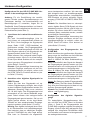
Sehr geehrter Kunde,
Wir gratulieren Ihnen zum Kauf dieses hochwer-
tigen HELIX Verstärkers.
Audiotec Fischer setzt mit der HELIX P ONE MK2
neue Maßstäbe im Bereich der Verstärkertechnik.
Dabei protieren Sie als Kunde direkt von unserer
mehr als 30-jährigen Erfahrung in der Forschung
und Entwicklung von Audiokomponenten.
Dieser Verstärker wurde von uns nach neuesten
technischen Erkenntnissen entwickelt und
zeichnet sich durch hervorragende Verarbeitung
und eine überzeugende Anwendung ausgereifter
Technologien aus.
Viel Freude an diesem Produkt wünscht Ihnen das
Team von
AUDIOTEC FISCHER
Allgemeines zum Einbau von HELIX-Kompo-
nenten
Um alle Möglichkeiten des Produktes optimal aus-
schöpfen zu können, lesen Sie bitte sorgfältig die
nachfolgenden Installationshinweise. Wir garan-
tieren, dass jedes Gerät vor Versand auf seinen
einwandfreien Zustand überprüft wurde.
Vor Beginn der Installation unterbrechen Sie
den Minusanschluss der Autobatterie.
Wir empfehlen Ihnen, die Installation von einem
Einbauspezialisten vornehmen zu lassen, da
der Nachweis eines fachgerechten Einbaus und
Anschlusses des Gerätes Voraussetzung für die
Garantieleistungen sind.
Installieren Sie Ihren Verstärker an einer trocke-
nen Stelle im Auto und vergewissern Sie sich,
dass der Verstärker am Montageort genügend
Kühlung erhält. Montieren Sie das Gerät nicht in
zu kleine, abgeschlossene Gehäuse ohne Luftzir-
kulation oder in der Nähe von wärmeabstrahlen-
den Teilen oder elektronischen Steuerungen des
Fahrzeuges. Im Sinne der Unfallsicherheit muss
der Verstärker professionell befestigt werden. Die-
ses geschieht über Schrauben, die in eine Mon-
tageäche eingeschraubt werden, die wiederum
genügend Halt bieten muss.
Bevor Sie die Schrauben im Montagefeld befes-
tigen, vergewissern Sie sich, dass keine elektri-
schen Kabel und Komponenten, hydraulische
Bremsleitungen, der Benzintank etc. dahinter
verborgen sind. Diese könnten sonst beschädigt
werden. Achten Sie bitte darauf, dass sich solche
Teile auch in der doppelten Wandverkleidung ver-
bergen können.
Allgemeines zum Anschluss des P ONE MK2
Verstärkers
Der Verstärker darf nur in Kraftfahrzeuge einge-
baut werden, die den 12 V-Minuspol an Masse
haben. Bei anderen Systemen können der HELIX
Verstärker und die elektrische Anlage des Kfz be-
schädigt werden. Die Plusleitung für die gesamte
Anlage sollte in einem Abstand von max. 30 cm
von der Batterie mit einer Hauptsicherung abge-
sichert werden. Der Wert der Sicherung errechnet
sich aus der maximalen Stromaufnahme der Car-
Hi Anlage.
Verwenden Sie zum Anschluss des Verstär-
kers an die Stromversorgung des Fahrzeugs
ausschließlich geeignete Kabel mit ausrei-
chendem Kabelquerschnitt. Die Sicherungen
im Verstärker dürfen nur mit den gleichen Wer-
ten (4 x 30 A) ersetzt werden, um eine Beschä-
digung des Gerätes zu verhindern. Höhere
Werte können zu gefährlichen Folgeschäden
führen!
Die Kabelverbindungen müssen so verlegt sein,
dass keine Klemm-, Quetsch- oder Bruchgefahr
besteht. Bei scharfen Kanten (Blechdurchführun-
gen) müssen alle Kabel gegen Durchscheuern
gepolstert sein. Ferner darf das Versorgungskabel
niemals mit Zuleitungen zu Vorrichtungen des Kfz
(Lüftermotoren, Brandkontrollmodulen, Benzinlei-
tungen etc.) verlegt werden.
Herzlichen Glückwunsch!
Allgemeine Hinweise
de

4
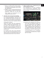
Anschluss- und Bedienelemente
1362
7
1 Status LED
Seite 8, Punkt 1
2 Lowlevel-Vorverstärkereingänge
Seite 5, Punkt 1
.3 Clipping LED
Seite 8, Punkt 2
4 Eingangsmodus-Schalter
Seite 5, Punkt 3
5 SPDIF DIRECT IN-Schalter
Seite 5, Punkt 4
6 Optischer Digitaleingang A / B
Seite 5, Punkt 2
7 Gain-Regler
Seite 6, Punkt 6
8 Lautsprecherausgang
Seite 7, Punkt 7
9 Anschluss Stromversorgung & Remote
Seite 6, Punkt 5
4
8 9
5

5
Hardware-Konguration
Kongurieren Sie den HELIX P ONE MK2 Ver-
stärker in der nachfolgenden Reihenfolge
Achtung: Für die Durchführung der nachfol-
genden Schritte werden Spezialwerkzeuge und
Fachwissen benötigt. Um Anschlussfehler und
Beschädigungen zu vermeiden, fragen Sie im
Zweifelsfall Ihren Einbauspezialisten und beach-
ten Sie zwingend die allgemeinen Anschluss- und
Einbauhinweise (siehe Seite 3).
1. Anschluss der Lowlevel-Vorverstärkerein-
gänge
Die zwei Vorverstärkereingänge (Line In-
put) können mit entsprechenden Kabeln an
die RCA / Cinch-Ausgänge der Signalquelle
(bspw. Radio / DSP / DSP-Verstärker) an-
geschlossen werden. Die Eingangsempnd-
lichkeit kann kanalübergreifend mit Hilfe des
Gain-Reglers optimal an die Signalquelle an-
gepasst werden ( siehe Seite 6, Punkt 6).
Dabei müssen nicht zwingend beide Eingän-
ge belegt werden. Wird nur ein Kanal belegt,
ist der Input Mode-Schalter auf den entspre-
chend genutzen Eingangskanal einzustellen
(siehe Seite 5, Punkt 3).
Hinweis: Eine gleichzeitige Verwendung des
optischen Eingangs zusammen mit den Vor-
verstärkereingängen ist möglich, sofern nicht
die SPDIF Direct In-Funktion aktiviert ist (sie-
he Seite 5, Punkt 4).
2. Anschluss einer digitalen Signalquelle im
SPDIF Format
Sofern Sie über eine Signalquelle mit op-
tischem Digitalausgang verfügen, kann diese
an den Verstärker angeschlossen werden. Die
Abtastrate (Sampling Rate) muss zwischen
28 - 96 kHz
liegen
. Das Eingangssignal wird
automatisch an die interne Abtastrate ange-
passt. Dabei müssen nicht zwingend beide
Eingangssignale genutzt werden. Soll nur ein
Signal genutzt werden, ist der Input Mode-
Schalter auf den entsprechenden Eingangs-
kanal einzustellen (siehe Seite 5, Punkt 3).
Wichtig: Das digitale Audiosignal einer Quel-
le ist üblicherweise nicht lautstärkegeregelt.
Das bedeutet, dass an sämtlichen Ausgän-
gen der P ONE MK2 der volle Pegel anliegt.
Dies kann im Extremfall die angeschlos-
senen Lautsprecher zerstören. Wir raten des-
halb dringend dazu, nur lautstärkegeregelte
Signalquellen anzuschließen, beispielsweise
DSP-Produkte mit einem optischen Signal-
ausgang (P SIX DSP ULTIMATE, BRAX DSP
etc.).
Hinweis: Der Verstärker kann nur unkompri-
mierte, digitale Stereo PCM-Signale mit einer
Abtastrate zwischen 28 kHz und 96 kHz ver-
arbeiten. Es können keine MP3- oder Dolby-
codierten Daten verarbeitet werden, sondern
ausschließlich Stereosignale.
Hinweis: Eine gleichzeitige Verwendung des
optischen Eingangs zusammen mit den Vor-
verstärkereingängen ist möglich, sofern die
SPDIF Direct In-Funktion nicht aktiviert ist
( siehe Seite 5, Punkt 4).
3. Konguration des Eingangsmodus der
P ONE MK2
Nach Anschluss des gewünschten Signalein-
gangs muss der Verstärker an die Anzahl der
belegten Eingänge angepasst werden.
Mono A: Wählen Sie diese Schalterstellung,
wenn ausschließlich das Signal des Kanals A
als Eingangssignal genutzt werden soll. Bei-
spielsweise wenn nur ein Monosignal für Sub-
wooferanwendungen zur Verfügung steht.
Mono B: Wählen Sie diese Schalterstellung,
wenn ausschließlich das Signal des Kanals B
als Eingangssignal genutzt werden soll. Bei-
spielsweise wenn nur ein Monosignal für Sub-
wooferanwendungen zur Verfügung steht.
Stereo: Bei Belegung beider Eingangskanäle
(A & B) wählen Sie bitte dieses Schalterstel-
lung. Aus dem Stereosignal wird dann ein op-
timiertes Summensignal gebildet.
Hinweis: Der Schalter beeinusst den Vorver-
stärker- und Digitaleingang.
4. Konguration des digitalen Signalein-
gangs
Für bestmögliche Klangperformance kön-
nen mit Hilfe des SPDIF Direct In-Schalters
(Seite 4, Punkt 5) die Eingangsstufen der
P ONE MK2 umgangen und das am optischen
Eingang (Optical Input A/B) anliegende Digi-
talsignal vom integrierten DA-Wandler direkt
und verlustfrei zum internen Leistungsverstär-
ker weitergeleitet werden.
de

6
Hardware-Konguration
On: Aktiviert die direkte Signalweiterleitung
für beste Klangperformance.
O: Wählen Sie diese Schalterstellung, so-
fern Sie die Gain-Regelung zur Einstel-
lung der Eingangsempnlichkeit benöti-
gen (werkseitig).
Hinweis: Der Schalter beeinusst ausschließ-
lich die Signalführung des optischen Ein-
gangs. Steht der Schalter auf „On“, sind die
Lowlevel-Vorverstärkereingänge sowie der
Gain-Regler ohne Funktion!
5. Anschluss der Stromversorgung & Remote
Vor dem Anschluss des +12 V
Versorgungskabels an das Bordnetz muss
die Autobatterie abgeklemmt werden.
Achten Sie unbedingt auf eine korrekte Pola-
rität.
+12 V: Anschluss für die Plusleitung.
Das +12 V Stromkabel ist am Pluspol der Bat-
terie anzuschließen. Die Plusleitung sollte in
einem Abstand von max. 30 cm von der Bat-
terie mit einer Hauptsicherung abgesichert
werden. Der Wert der Sicherung errechnet
sich aus der maximalen Stromaufnahme der
gesamten Car-Hi Anlage (P ONE MK2 =
max. 120 A RMS bei 12 V Bordnetz).
Verwenden Sie bei kurzen Leitungen (< 1 m)
einen Querschnitt von mindestens 16 mm².
Bei längeren Leitungen empfehlen wir einen
Querschnitt von 25 mm² bis 35 mm².
GND: Anschluss für die Masseleitung. Das
Massekabel muss an einer nicht isolierten
Stelle mit dem Kfz-Chassis oder direkt mit
dem Minuspol der Autobatterie verbunden
werden. Der Kabelquerschnitt sollte den glei-
chen Durchmesser wie die Plusleitung haben.
Ein nicht ausreichender Massekontakt führt
zu unerwünschten Störgeräuschen und Fehl-
funktionen.
REM: Der Remote-Eingang dient zum Ein-
und Ausschalten der P ONE MK2. Dieser
muss unbedingt mit dem Remote-Ausgang
der unmittelbar vorgeschalteten Komponen-
te, welche das Eingangssignal für die P ONE
MK2 liefert, verbunden werden. Beispielswei-
se dem Remote-Ausgang einer vorgeschal-
teten P SIX DSP ULTIMATE. Es wird dringend
davon abgeraten, den Remote-Eingang des
Verstärkers über das Zündungsplus des Fahr-
zeugs zu steuern, um Störgeräusche beim Ein-
und Ausschalten zu vermeiden.
6. Einstellung der Eingangsempndlichkeit
ACHTUNG: Es ist zwingend notwen-
dig, die Eingangsempndlichkeit der
P ONE MK2 an die Signalquelle anzupas-
sen, um eine bestmögliche Signalqualität
zu garantieren und Schäden am Verstärker
zu vermeiden.
Mit Hilfe des Gain-Reglers kann die Eingangs-
empndlichkeit optimal an die Signalquelle
angepasst werden.
Dieser Regler ist kein Lautstärkeregler, son-
dern dient nur der Anpassung.
Die Einstellung des Reglers beeinusst eben-
falls den optischen Digitaleingang, sofern der
SPDIF Direct In-Schalter auf „O“ steht.
Die Gain-Regelbereiche sind:
Line Input: 0,5 - 8,0 Volt
Optical Input: 0 - 24 dB
Sollte die Signalquelle eine zu niedrige Aus-
gangsspannung liefern, kann die Eingangs-
empndlichkeit über den Gain-Regler stufen-
los angehoben werden.
Die Clipping LED (siehe Seite 4, Punkt 3)
dient dabei als Kontrollinstrument.
Hinweis: Schließen Sie während dieser Pro-
zedur keine Lautsprecher an die Ausgänge
des Verstärkers an.
Zur Anpassung der Eingangsempndlichkeit
führen Sie bitte die folgenden Schritte durch:
1. Schalten Sie den Verstärker ein.
2. Drehen Sie die Lautstärke Ihres Radios
auf 90 % der Gesamtlautstärke und spie-
len Sie ein geeignetes Testsignal, z.B.
Rosa Rauschen, (Vollaussteuerung 0 dB)
ab.

7
3. Sollte die Clipping LED bereits leuchten,
verringern Sie mit Hilfe des Gain-Reglers
die Eingangsempndlichkeit, bis die Clip-
ping LED erlischt.
4. Erhöhen Sie die Eingangsempndlichkeit
durch Rechtsdrehung bis die Clipping LED
aueuchtet. Drehen Sie nun den Gain-
Regler gegen den Uhrzeigersinn bis die
Clipping LED wieder erlischt.
7. Anschluss der Lautsprecherausgänge
Die Lautsprecherausgänge können direkt mit
den Lautsprecherleitungen verbunden wer-
den. Verbinden Sie niemals die Lautsprecher-
leitungen mit der Kfz-Masse (Fahrzeugkaros-
serie). Dieses kann Ihren Verstärker und Ihre
Lautsprecher zerstören.
Achten Sie darauf, dass alle Lautsprecher-
systeme phasenrichtig angeschlossen sind,
d.h. Plus zu Plus und Minus zu Minus. Ver-
tauschen von Plus und Minus hat einen To-
talverlust der Basswiedergabe zur Folge. Der
Pluspol ist bei den meisten Lautsprechern ge-
kennzeichnet.
Die Impedanz darf 1 Ohm nicht unterschrei-
tenn, da sonst die Schutzschaltung des Ver-
stärkers aktiviert wird. Beispiele für den Laut-
sprecheranschluss nden Sie auf Seite 9 .
8. Optional: Aktivierung / Deaktivierung des
internen Subsonic-Filters
Die P ONE MK2 ist mit einem schaltbaren
21 Hz Subsonic-Filter ausgestattet. Dieser
kann im Inneren des Geräts aktiviert bzw. de-
aktiviert werden.
On: Subsonic-Filter aktiviert (werkseitig).
O: Subsonic-Filter deaktiviert. Der Subsonic
Filter sollte nur deaktiviert werden, so-
fern der Verstärker durch einen digitalen
Signalprozessor (DSP) oder DSP-Ver-
stärker angesteuert wird. Zusätzlich ist
im vorgeschalteten DSP / DSP-Verstärker
ein Subsonic- (Hochpass-) Filter mit einer
Grenzfrequenz von min. 20 Hz sowie ei-
ner Flankensteilheit von min. 36 dB/Okta-
ve (Butterworth-Charakteristik) im Signal-
pfad vorzusehen.
de

8
Weitere Funktionen
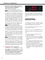
1. Status LED
Die Status LED zeigt den Betriebszustand des
Verstärkers an.
Grün: Verstärker eingeschaltet und betriebs-
bereit.
Gelb / grün blinkend: Überhitzungsschutz ak-
tiv. Der Überhitzungsschutz begrenzt die Aus-
gangsleistung dynamisch und ermöglicht es,
in Abhängigkeit von der Temperatur immer die
maximale Ausgangsleistung zu erzielen.
Gelb: Überhitzung des Verstärkers. Die in-
terne Temperaturüberwachung schaltet das
Gerät ab, bis ein sicherer Betrieb wieder ge-
währleistet werden kann.
Gelb blinkend: Sicherungen im Inneren des
Geräts zerstört. Prüfen Sie die Sicherungen
und tauschen diese gegebenenfalls aus. Die
Sicherungen im Verstärker dürfen nur mit den
gleichen Werten (4 x 30 Ampere) ersetzt wer-
den, um eine Beschädigung des Gerätes zu
verhindern. Höhere Werte können zu gefähr-
lichen Folgeschäden führen!
Rot:
Protection Mode aktiv. Dieser kann unter-
schiedliche Ursachen haben.
Der Verstärker
ist mit verschiedenen elektronischen Schutz-
schaltungen ausgestattet. Diese schalten den
Verstärker bei Über- und Unterspannung,
Kurzschluss am Lautsprecherausgang und
Fehlanschluss ab. Prüfen Sie in diesem Fall
alle Anschlüsse auf Fehler, wie z.B. Kurz-
schlüsse, fehlerhafte Verbindungen oder
Falscheinstellungen. Sollte sich der Verstär-
ker nach Beseitigung der Fehlerquelle nicht
wieder einschalten lassen, liegt ein Defekt vor.
2. Clipping LED
In der Regel ist die LED aus und leuchtet nur
auf, wenn die Eingangsstufe übersteuert wird.
On (rot): Einer der Signaleingänge wird über-
steuert. Senken Sie die Eingangs-
empndlichkeit mit Hilfe des Gain-
Reglers ab, bis die LED erlischt.
Wie Sie die Eingangsempndlich-
keit absenken, ist auf Seite 6 unter
Punkt 6 nachzulesen.

9
Kongurationsbeispiele
de
Mono-Subwooferanwendung
Subwoofer mit einer Schwingspule (Single Voice Coil)
RMS-Ausgangsleistung ≤ 1% THD+N:
1 x 4 Ohm: 500 Watt
1 x 2 Ohm: 880 Watt
1 x 1 Ohm: 1.500 Watt
Hinweis: Die Übernahmefrequenzen für den Hoch- bzw. Tiefpass müssen mit Hilfe eines vorge-
schalteten DSPs oder DSP-Verstärkers eingestellt werden.
Parallelbetrieb
Zwei identische Subwoofer mit einer Schwingspule (Single
Voice Coil) oder ein Subwoofer mit Doppelschwingspule
(Dual Voice Coil) werden parallel geschaltet.
Hinweis: Die Parallelschaltung von zwei Schwingspulen
führt zur Halbierung der Impedanz!
RMS-Ausgangsleistung ≤ 1% THD+N:
Zwei Subwoofer mit 1 x 4 Ohm entsprechen einer
Gesamtimpedanz von 2 Ohm: 880 Watt
Ein Subwoofer mit 2 x 4 Ohm entspricht ebenso einer
Gesamtimpedanz von 2 Ohm: 880 Watt
Zwei Subwoofer mit 1 x 2 Ohm entsprechen einer
Gesamtimpedanz von 1 Ohm: 1.500 Watt
Ein Subwoofer mit 2 x 2 Ohm entspricht ebenso einer
Gesamtimpedanz von 1 Ohm: 1.500 Watt
Hinweis: Das Parallelschalten von 1 Ohm Schwingspulen
führt zu Abschaltung des Verstärkers.
Ein Subwoofer mit
Doppelschwingspule
(Dual Voice Coil)
Zwei Subwoofer mit einer
Schwingspule
(Single Voice Coil)

10
Kongurationsbeispiele
Ein Subwoofer mit
Doppelschwingspule
(Dual Voice Coil)
Zwei Subwoofer mit einer
Schwingspule
(Single Voice Coil)
Reihenbetrieb
Zwei identische Subwoofer mit einer Schwingspule (Single
Voice Coil) oder ein Subwoofer mit Doppelschwingspule
(Dual Voice Coil) werden in Reihe geschaltet.
Hinweis: Die Reihenschaltung von zwei Schwingspulen
führt zur Verdopplung der Impedanz!
RMS-Ausgangsleistung ≤ 1% THD+N:
Zwei Subwoofer mit 1 x 2 Ohm entsprechen einer
Gesamtimpedanz von 4 Ohm: 500 Watt
Ein Subwoofer mit 2 x 2 Ohm entspricht ebenso einer
Gesamtimpedanz von 4 Ohm: 500 Watt
Zwei Subwoofer mit 1 x 1 Ohm entsprechen einer
Gesamtimpedanz von 2 Ohm: 880 Watt
Ein Subwoofer mit 2 x 1 Ohm entspricht ebenso einer
Gesamtimpedanz von 2 Ohm: 880 Watt
Hinweis: Die Reihenschaltung von 4 Ohm Sub woofern führt
zu einer sehr geringen Ausgangsleistung des Verstärkers
und ist daher nicht empfehlenswert!
Hinweis: Der Minuspol der ersten Schwingspule muss mit
dem Pluspol der zweiten Schwingspule verbunden werden.
Hierzu sollte derselbe Kabelquerschnitt gewählt werden,
welcher auch für den Anschluss des Subwoofers genutzt
wird.

11
de
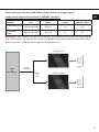
Lautsprecher R
Digitales
Stereosignal
Optischer
Audio-
Splitter
P ONE MK2 (Links)
P ONE MK2 (Rechts)
Lautsprecher L
DSP
oder
DSP-Verstärker
Stereoanwendung mit zwei P ONE MK2 Verstärkern und Nutzung eines Digitalsignals
Kongurationshinweise für die einzelnen P ONE MK2 Verstärker:
Verstärker
Verstärker-
Eingang
Input Mode-
Schalter
SPDIF Direct In-
Schalter
Interner
Subsonic-Filter
P ONE MK2
(Links) Optical Input A/B Mono A An (On) Aus (O)
P ONE MK2
(Rechts) Optical Input A/B Mono B An (On) Aus (O)
WICHTIG: Die Übernahmefrequenzen für den Hoch- bzw. Tiefpass müssen mit Hilfe eines vorgeschal-
teten DSP oder DSP-Verstärker eingestellt werden. Wir empfehlen einen Subsonic- (Hochpass-) Filter
mit einer Grenzfrequenz von min. 20 Hz sowie einer Flankensteilheit von min. 36 dB/Oktave (Butter-
worth-Charakteristik).

12
Leistung RMS ≤ 1% THD+N
- @ 4 Ohm .................................................................... 1 x 500 Watt
- @ 2 Ohm .................................................................... 1 x 880 Watt
- @ 1 Ohm .................................................................... 1 x 1.500 Watt
Max. Leistung pro Kanal* ............................................. Bis zu 1.800 Watt RMS @ 1 Ohm
Verstärkertechnologie ...................................................Class D
Eingänge ...................................................................... 2 x Cinch
1 x Optisch SPDIF (28 - 96 kHz)
1 x Remote In
Eingangsempndlichkeit ............................................... Cinch: 0,5 V - 8 V
Eingangsimpedanz ....................................................... Cinch: 20 kOhm
Ausgänge ..................................................................... 1 x Lautsprecherausgang
Signalwandler für den Digitaleingang ........................... BurrBrown 32 Bit DA-Wandler
Frequenzbereich...........................................................21 Hz - 40.000 Hz
Subsonic Filter ..............................................................21 Hz / Butterworth 48 dB/Okt.
Signal- / Rauschabstand (A-bewertet).......................... Digitaleingang: 110 dB
Analogeingang: 110 dB
Klirrfaktor (THD) ...........................................................< 0,01 %
Dämpfungsfaktor ..........................................................> 450
Betriebsspannung.........................................................10,5 - 17 Volt (max. 5 Sek. bis hinab zu 6 Volt)
Leerlaufstromaufnahme................................................1500 mA
Sicherung .....................................................................4 x 30 A LP-Mini-Stecksicherung
Leistungsaufnahme ......................................................DC 12 V 160 A max.
Umgebungstemperaturbereich für den Betrieb ............-40 °C bis +70 °C
Zusätzliche Features .................................................... Eingangsmodus-Schalter, SPDIF Direct In-
Schalter, Start-Stopfähigkeit
Abmessungen (H x B x T) ............................................50 x 260 x 190 mm
* In typischen Anwendungen als Subwoofer-Verstärker
Die Garantieleistung entspricht der gesetzlichen
Regelung. Von der Garantieleistung ausgeschlos-
sen sind Defekte und Schäden, die durch Über-
lastung oder unsachgemäße Behandlung ent-
standen sind. Eine Rücksendung kann nur nach
vorheriger Absprache in der Originalverpackung,
einer detaillierten Fehlerbeschreibung und einem
gültigen Kaufbeleg erfolgen. Technische Ände-
rungen, Druckfehler und Irrtümer vorbehalten!
Für Schäden am Fahrzeug oder Gerätedefekte,
hervorgerufen durch Bedienungsfehler des Ge-
rätes, können wir keine Haftung übernehmen.
Dieses Produkt ist mit einer CE-Kennzeichnung
versehen. Damit ist das Gerät für den Betrieb in
Fahrzeugen innerhalb der Europäischen Union
(EU) zertiziert.
Garantiehinweis
Technische Daten

13
General installation instructions for HELIX
components
To prevent damage to the unit and possible injury,
read this manual carefully and follow all installa-
tion instructions. This product has been checked
for proper function prior to shipping and is guaran-
teed against manufacturing defects.
Before starting your installation, disconnect
the battery’s negative terminal to prevent
damage to the unit, re and / or risk of injury.
For a proper performance and to ensure full war-
ranty coverage, we strongly recommend to get this
product installed by an authorized HELIX dealer.
Install your HELIX P ONE MK2 in a dry location
with sucient air circulation for proper cooling of
the equipment. The amplier should be secured
to a solid mounting surface using proper mounting
hardware. Before mounting, carefully examine the
area around and behind the proposed installation
location to insure that there are no electrical ca-
bles or components, hydraulic brake lines or any
part of the fuel tank located behind the mounting
surface. Failure to do so may result in unpredict-
able damage to these components and possible
costly repairs to the vehicle.
General instruction for connecting the HELIX
P ONE MK2 amplier
The HELIX P ONE MK2 amplier may only be in-
stalled in vehicles which have a 12 Volts negative
terminal connected to the chassis ground. Any
other system could cause damage to the amplier
and the electrical system of the vehicle.
The positive cable from the battery for the com-
plete system should be provided with a main fuse
at a distance of max. 30 cm from the battery. The
value of the fuse is calculated from the maximum
total current input of the car audio system.
Use only suitable cables with sucient cable
cross-section for the connection of HELIX
P ONE MK2. The fuses may only be replaced
by identically rated fuses (4 x 30 A) to avoid
damage of the amplier.
Prior to installation, plan the wire routing to
avoid any possible damage to the wire harness.
All cabling should be protected against possible
crushing or pinching hazards. Also avoid routing
cables close to potential noise sources such as
electric motors, high power accessories and other
vehicle harnesses.
Congratulations!
General instructions
Dear Customer,
Congratulations on your purchase of this
innovative and high-qual ity HELIX product.
Thanks to more than 30 years of experience in
research and development of audio products the
HELIX P ONE MK2 sets new standards in the
range of ampliers.
We wish you many hours of enjoyment with your
new HELIX P ONE MK2.
Yours,
AUDIOTEC FISCHER
en

14
Connectors and control units
1362
7
1 Status LED
Page 18, point 1
2 Lowlevel line inputs
Page 15, point 1
.3 Clipping LED
Page 18, point 2
4 Input mode switch
Page 15, point 3
5 SPDIF DIRECT IN switch
Page 15, point 4
6 Optical digital input A / B
Page 15, point 2
7 Gain control
Page 16, point 6
8 Speaker output
Page 17, point 7
9 Power & Remote connector
Page 16, point 5
4
8 9
5

15
en
Hardware conguration
Congure the HELIX P ONE MK2 as follows
Caution: Carrying out the following steps will re-
quire special tools and technical knowledge. In or-
der to avoid connection mistakes and / or damage,
ask your dealer for assistance if you have any
questions and follow all instructions in this manual
(see page 13). It is recommended that this unit will
be installed by an authorized HELIX dealer.
1. Connecting the lowlevel line inputs
These two lowlevel line inputs can be connect-
ed to signal sources such as head units / radi-
os / DSPs / DSP ampliers using appropriate
cables. The input sensitivity for all channels
can be optimally adapted to the signal source
using the gain control (see page 16, point 6).
It is not mandatory to use both lowlevel line in-
puts. If only one channel will be connected the
input mode switch must be set to the appropri-
ate input channel used (see page 15, point 3).
Note: It is possible to use the optical input and
the lowlevel line input at the same time if the
SPDIF Direct In function is deactivated (see
page 15, point 4).
2. Connecting a digital signal source in
SPDIF format
If you have a signal source with an optical digi-
tal output you can connect it to the amplier
using the appropriate input. The sampling rate
must be between 28 and 96 kHz. The input
signal is automatically adapted to the internal
sample rate.
It is not mandatory to use both input signals.
If only one signal should be used, the input
mode switch must be set to the appropriate
input channel (see page 15, point 3).
Important: The signal of a digital audio
source normally does not contain any informa-
tion about the volume level. Keep in mind that
this will lead to full level on the outputs of the
HELIX P ONE MK2. This may cause severe
damage to your speakers. We strongly rec-
ommend to only use volume controlled audio
sources! For example DSP devices with opti-
cal signal output like P SIX DSP ULITMATE,
BRAX DSP etc.
Note: The HELIX P ONE MK2 can only handle
uncompressed digital stereo signals in PCM
format with a sample rate between 28 kHz and
96 kHz and no MP3- or Dolby-coded digital
audio stream!
Note: It is possible to use the optical input and
the lowlevel line input at the same time if the
SPDIF Direct In function is deactivated (see
page 15, point 4).
3. Conguration of the ampliers input mode
After connecting the desired signal inputs, the
amplier must be adapted to the number of
used inputs.
Mono A: Select this switch setting if only the
signal of channel A should be used as input
signal. For example, if only a mono signal is
provided for subwoofer applications.
Mono B: Select this switch setting if only the
signal of channel B should be used as input
signal. For example, if only a mono signal is
provided for subwoofer applications.
Stereo: Select this switch setting if both input
channels (A and B) are used. In this mode an
optimized sum signal is generated by the input
signals of the channels A and B.
Note: The setting of the switch aects both
the lowlevel line inputs as well as the optical
digital input.
4. Conguration of the digital signal input
For best possible sound performance, the
SPDIF Direct In switch (page 14, point 5) can
be used to bypass the input stages of the
P ONE MK2 and to route the audio signal from
the digital input (Optical Input A/B) directly and
without any detours to the output stages of the
amplier.
On: Activates direct signal routing for best
sound performance.
O: Select this switch position if you need the
gain control for adjusting the input sensi-
tivity (by default).
Note: The switch only aects the signal rout-
ing of the optical input. If the switch is set to
“On”, the lowlevel line inputs as well as the
gain control are without function!

16
Hardware conguration
5. Connection to power supply & remote
Make sure to disconnect the battery before
installing the HELIX P ONE MK2!
Make sure of correct polarity.
+ 12V: Connector for the positive cable.
Connect the +12 V power cable to the positive
terminal of the battery. The positive wire from
the battery to the ampliers power terminal
needs to have an inline fuse at a distance of
no more than 12 inches (30 cm) from the bat-
tery. The value of the fuse is calculated from
the maximum total current input of the whole
car audio system (P ONE MK2 = max. 120 A
RMS at 12 V RMS power supply). If your pow-
er wires are short (less than 1 m / 40”) then
a wire gauge of 16 mm² / AWG 6 will be suf-
cient. In all other cases we strongly recom-
mend gauges of 25 - 35 mm² / AWG 4 – 2!
GND: Connector for the ground cable.
The ground wire should be connected to a
common ground reference point (this is locat-
ed where the negative terminal of the battery
is grounded to the metal body of the vehicle),
or to a prepared metal location on the vehicle
chassis, i.e. an area which has been cleaned
of all paint residues. The cable should have
the same gauge as the +12 V wire. Inade-
quate grounding causes audible interference
and malfunctions.
REM: The remote input is used to switch
on and o the P ONE MK2. It is mandato-
ry to connect this input to the remote output
of the preconnected device that provides
the input signal to the P ONE MK2.
For ex-
ample the remote output of a preconnected
P SIX DSP ULTIMATE.
We do not recommend
controlling the remote input via the ignition
switch to avoid pop noise during turn on / o.
6. Adjustment of the input sensitivity
ATTENTION: It is mandatory to prop-
erly adapt the input sensitivity of the
P ONE MK2 to the signal source in order
to achieve the best possible signal quality
and to avoid damage to the amplier.
The input sensitivity can be optimally adapted
to the signal source using the gain control.
This is not a volume control, it´s only for ad-
justing the amplier gain. The setting of the
control also aects the digital signal input if
the SPDIF Direct In switch is set to “O” po-
sition.
The gain control range is:
Line Input: 0.5 - 8.0 Volts
Optical Input: 0 - 24 dB
If the signal source doesn´t provides enough
output voltage, the input sensitivity can be
smoothly increased via the gain control.
The Clipping LED (see page 14, point 3)
serves as monitoring tool.
Note: Don‘t connect any loudspeakers to the
outputs of the HELIX P ONE MK2 during this
setup.
For adjustment please proceed as follows:
1. Turn on the amplier.
2. Adjust the volume of your radio to approx.
90 % of the max. volume and playback
an appropriate test tone, e.g. pink noise
(0 dB).
3. If the Clipping LED already lights up, you
have to reduce the input sensitivity via the
gain control until the LED turns o.
4. Increase the input sensitivity by turning the
gain control clockwise until the Clipping
LED lights up. Now turn the control coun-
terclockwise until the Clipping LED turns
o again.

17
en
7. Connecting the loudspeaker outputs
The loudspeaker outputs can be connect-
ed directly to the wires of the loudspeakers.
Never connect any of the loudspeaker cables
with the chassis ground as this will damage
your amplier and your speakers. Ensure that
the loudspeakers are correctly connected (in
phase), i.e. plus to plus and minus to minus.
Exchanging plus and minus causes a total
loss of bass reproduction. The plus pole is
indicated on most speakers. The impedance
must not be lower than 1 Ohm, otherwise the
amplier protection will be activated. Exam-
ples for speaker congurations can be found
on page 19 et sqq.
8. Optional: Activation / deactivation of the
internal subsonic lter
The P ONE MK2 is equipped with a switch-
able 21 Hz subsonic lter. The lter can be
activated or deactivated inside the device.
On: Subsonic lter activated (by default).
O: Subsonic lter deactivated. The subsonic
lter should only be deactivated if the am-
plier is driven by a digital signal proces-
sor (DSP) or DSP amplier. In addition,
a subsonic (highpass) lter with a cut-o
frequency of min. 20 Hz and a slope of
min. 36 dB/octave (Butterworth character-
istic) must be provided in the signal path
of the preconnected DSP / DSP amplier.

18
Additional functions
1. Status LED
The Status LED indicates the operating mode
of the amplier.
Green: Amplier is ready for operation.
Yellow / green ashing: Overheat control
is active. The overheat control dynamically
limits the output power and allows to always
achieve the maximum output power depend-
ing on the temperature.
Yellow: The amplier is overheated. The in-
ternal temperature protection shuts down the
device until it reaches a safe temperature lev-
el again.
Yellow ashing: The fuses inside the device
are blown. Please check the fuses and, if
necessary, replace them. They may only be
replaced by identically rated fuses (4 x 30 Am-
pere) to avoid damage of the amplier.
Red: A malfunction has occurred that may
have dierent root causes. The HELIX
P ONE MK2 is equipped with protection
circuits against over- and undervoltage,
short-circuit on loudspeakers and reverse
connection. Please check for connecting
failures such as short-circuits or other wrong
connections. If the amplier does not turn on
after that it is defective and has to be sent to
your local authorized dealer for repair service.
2. Clipping LED
Normally the Clipping LED is o and only
lights up if the input stage is overdriven.
On (red): One of the signal inputs is over-
driven. Reduce the input sensitivity
using the gain control until the LED
goes out. How to reduce the input
sensitivity is described on page 16
point 6.

19
en
Mono subwoofer application
Subwoofer with one voice coil (single voice coil)
RMS output power ≤ 1% THD+N:
1 x 4 Ohms: 500 Watts
1 x 2 Ohms: 880 Watts
1 x 1 Ohm: 1,500 Watts
Note: The crossover frequencies for the high- and lowpass must be set in the preconnected
DSP / DSP amplier.
Parallel operation
Two subwoofers with one voice coil (single voice coil) or
one subwoofer with dual voice coil are connected in parallel.
Note: The parallel connection of two voice coils will result in
halving the impedance!
RMS output power ≤ 1% THD+N:
Two subwoofers with 1 x 4 Ohms correspond to a total
impedance of 2 Ohms: 880 Watts
One subwoofer with 2 x 4 Ohms also corresponds to a total
impedance of 2 Ohms: 880 Watts
Two subwoofers with 1 x 2 Ohms correspond to a total
impedance of 1 Ohm: 1,500 Watts
One subwoofer with 2 x 2 Ohms also corresponds to a total
impedance of 1 Ohm: 1,500 Watts
Note: The parallel connection of 1 Ohm voice coils will re-
sult in shutdown of the amplier.
One subwoofer with
dual voice coil
Two subwoofers with
single voice coil
Conguration examples

20
One subwoofer with
dual voice coil
Two subwoofers with
single voice coil
In series
Two subwoofers with one voice coil (single voice coil) or
one subwoofer with dual voice coil are connected in series.
Note: The connection of two voice coils in series will result
in doubling the impedance!
RMS output power ≤ 1% THD+N:
Two subwoofers with 1 x 2 Ohms correspond to a total
impedance of 4 Ohms: 500 Watts
One Subwoofer with 2 x 2 Ohms also corresponds to a total
impedance of 4 Ohms: 500 Watts
Two subwoofers with 1 x 1 Ohm correspond to a total
impedance of 2 Ohms: 880 / 1,760 Watts
One subwoofer with 2 x 1 Ohm also correspond to a total
impedance of 2 Ohms: 880 Watts
Note: The negative terminal of the rst voice coil has to be
connected to the positive terminal of the second voice coil
by using a speaker wire with the same gauge as the other
speaker.
Conguration examples
Seite wird geladen ...
Seite wird geladen ...
Seite wird geladen ...
Seite wird geladen ...
-
 1
1
-
 2
2
-
 3
3
-
 4
4
-
 5
5
-
 6
6
-
 7
7
-
 8
8
-
 9
9
-
 10
10
-
 11
11
-
 12
12
-
 13
13
-
 14
14
-
 15
15
-
 16
16
-
 17
17
-
 18
18
-
 19
19
-
 20
20
-
 21
21
-
 22
22
-
 23
23
-
 24
24


Helix P One MK2 1-Channel High-Res Amplifier Benutzerhandbuch
- Kategorie
- Auto-Audio-Verstärker
- Typ
- Benutzerhandbuch