ENGLISH
Please read the following before installing
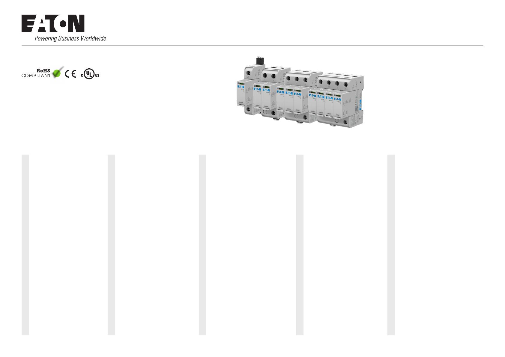
your Surge Protective Device:
DEUTSCH
Bitte lesen Sie die folgenden Angaben vor
Installation der Überspannungsschutzgerät:
FRANÇAIS
Veuillez lire les instructions suivantes avant
d’installer votre parafoudre:
ESPAÑOL
Lea las siguientes instrucciones antes de la
instalación de su dispositivo de protección
contra sobretensiones:
ITALIANO
Prima di installare il limitatore di sovratensione
(SPD: Surge Protective Device), leggere attenta-
mente quanto segue:
• Verify the system voltage and congu-
ration on the label is appropriate for the
application.
• Risk of Electric Shock – Installation
and maintenance should be performed
by qualied personnel only.
• Disconnect from energized circuits
before installing or servicing.
• Safety rules and regulations applicable
to all devices connected to power lines
should always be followed. National
standards and safety regulations must
be followed.
• The external mechanical integrity of
the device must be checked before in-
stallation. Products with visible damage
should not be installed.
• Its use is only permitted within the
limits shown and stated in these
installation instructions. Opening or
tampering with the device invalidates
the warranty.
• Connecting leads shall be kept as
short as possible, without loops and
not exceed 0.5m in total length per
SPD.
• The minimum distance of the SPD
from any grounded conductive surface
at which the SPD can be installed is
0 mm.
• This is open type SPD intended for in-
stallation within a suitable enclosure in
accordance with the National Electrical
Code, ANSI/NFPA 70.
• Sicherstellen, dass die Systemspannung
und -konguration auf dem Etikett für die
Anwendung geeignet ist.
• Stromschlaggefahr – Installation und
Wartung sollten nur vom Fachmann
durchgeführt werden.
• Gerät vor der Installation oder Wartung/
Reparatur von spannungsführenden
Leitungen trennen.
• Die Sicherheitsvorschriften und -regeln für
alle an Stromleitungen angeschlossenen
Geräte sind stets zu befolgen. Vor Ort gel-
tende Normen und Sicherheitsvorschriften
befolgen.
• Vor der Installation ist die externe
mechanische Unversehrtheit des Geräts
sicherzustellen. Produkte mit sichtbaren
Schäden dürfen nicht installiert werden.
• Das Gerät ist nur für den Betrieb innerhalb
der angegebenen Grenzwerte zugelassen.
Wird das Gerät geöffnet oder manipuliert,
erlischt die Garantie.
• Anschlussleitungen sollten so kurz wie
möglich gehalten werden, dürfen keine
Schleifen enthalten und nicht länger
0,5 m sein.
• Der Mindestabstand zwischen dem SPD
und einer geerdeten Leiteräche, an der
das SPD installiert werden kann, beträgt
0 mm.
• Dies ist ein offener SPD-Typ, der zum
Einbau in ein geeignetes Gehäuse gemäß
dem National Electrical Code (ANSI /
NFPA 70) vorgesehen ist.
• Vériez que la tension et la conguration du
système sur l’étiquette du produit convient à
l’application
• Déconnectez le produit de circuits sous ten-
sion avant l’installation ou l’entretien
• Les règles de sécurité et les réglementations
applicables aux appareils connectés aux
lignes électriques doivent toujours être re-
spectées. Les normes nationales et les règles
de sécurité doivent être respectées
• L’intégrité mécanique externe du produit doit
être vériée avant l’installation. Les produits
présentant des dommages visibles ne doivent
pas être installés
• L’utilisation du produit est uniquement
autorisée dans les limites indiquées dans ce
manuel d’installation. Le désassemblage ou la
modication du produit annule sa garantie
• Les câbles de raccordement doivent être
aussi courts que possible, sans boucles et ne
pas dépasser une longueur totale de 50 cm
par parafoudre.
• La distance minimale du parafoudre par
rapport à toute surface conductrice mise à
la terre sur laquelle le parafoudre peut être
installé est de 0 mm.
• Il s’agit d’un SPD de type ouvert destiné
à être installé dans un boîtier approprié
conformément au National Electrical Code,
ANSI / NFPA 70.
• Compruebe que la tensión y conguración
del sistema que aparecen en la etiqueta
son adecuadas para su instalación.
• Riesgo de descarga eléctrica: únicamente
personal cualicado puede instalar o dar
mantenimiento a este dispositivo.
• Desconecte los circuitos con tensión antes
instalarlo o darle mantenimiento.
• Siga siempre todas las normativas y
reglamentos de seguridad pertinentes
a todos los dispositivos conectados a la
red eléctrica. Debe respetar la normativa
nacional y los reglamentos de seguridad.
• Compruebe la integridad mecánica exter-
na del dispositivo antes de su instalación.
Nunca instale productos que presenten
daños visibles.
• Sólo se permite utilizarse dentro de los
límites establecidos en estas instrucciones
de instalación. Abrir o alterar el dispositivo
anula la garantía.
• Las conexiones de cables deben ser
lo más cortas posibles, sin bucles y sin
exceder 0,5 m de longitud total por cada
SPD según la norma IEC 60364-5-53.
• La distancia mínima entre el SPD y la
supercie conductora conectada a tierra
en la que puede instalarse es de 0 mm.
• Este es un SPD de tipo abierto destinado
a la instalación dentro de un recinto ade-
cuado de acuerdo con el Código Eléctrico
Nacional, ANSI / NFPA 70.
• Vericare la tensione e la congurazione
del sistema sull’etichetta per capire se sono
appropriati per l’applicazione del dispositivo.
• Rischi di elettrocuzione – L’installazione e
la manutenzione devono essere effettuate
unicamente da personale qualicato.
• Togliere corrente ai circuiti, prima dell’instal-
lazione o della manutenzione.
• È necessario rispettare sempre le normative
e i regolamenti di sicurezza applicabili, per
tutti i dispositivi collegati alla linea elettrica. È
necessario rispettare gli standard nazionali e
i regolamenti di sicurezza.
• Prima dell’installazione, è necessario
vericare l’integrità meccanica esterna del
dispositivo. Non bisogna installare prodotti
che mostrino danni evidenti.
• Il suo uso è consentito solo entro i limiti
indicati e dichiarati in queste istruzioni di
installazione. L’apertura o la manomissione
del dispositivo causano l’annullamento della
garanzia.
• L’interconnessione delle parti conduttrici
deve essere la più corta possibile, evitando
la formazione di anelli e non deve comunque
superare gli 0,5m di lunghezza totale, per
gli SPD.
• La distanza minima del SPD da qualsiasi
supercie conduttrice con messa a terra, a
cui può essere installato un SPD, è di 0 mm.
• Si tratta di un SPD di tipo aperto destinato
all’installazione all’interno di un contenitore
idoneo in conformità al National Electrical
Code, ANSI / NFPA 70.
Eaton Corporation, 1000 Eaton Boulevard, Cleveland, OH 44122, United States
© 2022 by Eaton, www.eaton.com
Installation Instructions
Installationsanleitung
Manuel d’installation
Istruzioni per l’installazione
Instrucciones de Instalación
AG II IT DN Series
03.2022a / All Rights Reserved
For more information, please contact the Eaton Technical Resource Center
at 1-800-809-2772, option 4, option 2. You may submit inquiries via email to
spd@eaton.com and you can find more information at eaton.com/aegis.


