
NO
2
1
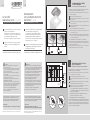
Fig. B
OK
Fig. C
Fig. A
+ 24
- (GND)
CTRL
TACHO
+
-
33K 3.9K
10K U
12V
12V
PWM
Speed setting
PWM 1-10 kHz
Air flow setting
with variable
resistance
Full
speed
Air flow setting
1V-10V
CUSTOMER CIRCUITS
CONNECTION
PULL-UP
RESISTANCE
(DC 10V)
10KΩ
ref. Fig. B
AC and DC
roof exhaust units - FL series
MOUNTING INSTRUCTIONS
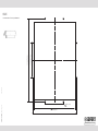
1 Cut the mounting hole on the top of enclosure
using the cut-out dimensions.
Position the roof exhaust unit on the pre-cut
hole and fix it to the enclosure using the fixing
screws supplied. Tighten the screws
with a torque of approx 1.5 Nm (13.28 Lbf.in).
2 Carry out the electrical connection as shown
in Fig. A for AC models and in Fig. B for DC
models.
EN
ENG
DE
Wechselstrom
(AC) und Gleichstrom (DC)
Dachlüfter FL Serie
MONTAGEANLEITUNG
1 Schneiden Sie mit Hilfe der Lochbildschablone
oben am Gehäuse den Bereich aus.
Positionieren Sie den Dachlüfter auf dem
Ausschnitt und befestigen Sie ihn mit den
mitgelieferten Befestigungsschrauben am
Gehäuse. Ziehen Sie die Schrauben mit einem
Drehmoment von ca. 1,5 Nm an.
2 Verbinden Sie die elektrischen Kabel analog dem
Verdrahtungsschema in Fig. A (AC-Modelle)
und Fig. B (DC-Modelle)
We recommend the wearing of suitable protective clothing:
• gloves EN 420 and EN 388 • safety glasses EN 166 - 170
Wir empfehlen geeignete Schutzkleidung zu tragen:
• Handschuhe EN 420 und EN 388 • Schutzbrille EN 166 - 170
GARANTIE
Die Garantie wird gemäss den gesetzlichen
Bestimmungen sowie den jeweils gültigen AGB’s gewährt.
Diese Installationsanleitung ist Bestandteil des Produktes
und muss allen die das Produkt verwenden zugängig sein.
Für Schäden die durch Nichtbeachtung dieser Anleitungen
entstehen, übernehmen wir keine Haftung.
Alle hier enthaltenen Angaben, Daten und Abbildungen können jederzeit
ohne Vorankündigung geändert werden.
REINIGUNG UND AUSTAUSCH
DER FILTERMATTE
NUR FÜR IP54, IP55 NICHT FÜR UL AUSFÜHRUNG
Achtung! Schalten Sie vor Arbeiten am Gerät die Netzspannung aus
und tragen Sie geeignete Schutzkleidung.
Während allen Operationen muss der Dachlüfter in einer horizontalen
Position mit dem Deckel nach oben liegen.
A Die 8 Schrauben ausdrehen und den Deckel entfernen.
B Die Filtermatte und das Metallnetz entfernen, Vorsicht vor scharfen
Kanten.
C Zur Reinigung kann die Filtermatte ausgewaschen oder ausgeklopft
werden, im Extremfall die Filtermatte austauschen.
D Wiederholen Sie die Schritte in umgekehrter Folge, um den
Dachlüfter zu schließen, bitte beachten Sie dass:
I sich die Filtermatte während dem Einsetzen nicht verbiegt und
dass der Kabeldurchgang vor dem Schließen des Deckels korrekt
geführt ist; (siehe Abbildung C)
II Deckelmontage: ziehen Sie die 4 Schrauben kreuzweise an, das
Drehmoment soll nicht mehr als 1,5 Nm sein;
III Schließlich überprüfen Sie ob der Lüfter frei laufen kann
.
Die Austauschhäufigkeit hängt von der Staubmenge und der Funktionszeit
ab; sie soll also durch den Benutzer von Mal zu Mal für jeden Einsatz
bestimmt werden. Eine schmutzige Filtermatte verringert die Leistung
des Filterlüfters und verursacht dadurch eine unzureichende Lüftung oder
sogar einen kompletten Lüftungsausfall.
DE
WARRANTY
For warranty conditions see “General Sales Conditions”.
The assembly instruction is an integral part of the product,
and must be available to everybody who works with
the product. We cannot accept any liability for damage
associated with failure to observe these instructions.
All specifications, data and drawings are subject to change without notice.
ADVICE
Disconnect the mains supply before carrying out any
operation on the product.
- The electrical connection must be carried out according
to the local norms and safety regulations which govern
the use of electrical material;
- Electrical connection must be carried out by qualified
personnel only;
- The power supply of the product must comply with the
rated values shown on the label.
- Polarity must be respected as indicated in the wiring
diagrams (Fig. A and Fig. B)
- The DC versions are in class III only if a safety isolating
transformer, or a AC/DC convertor with separate windings,
is used, the insulation of which complies with double
insulation or reinforced insulation requirements.
- Tachometer output 3 PULSE/REVOLUTION.
The cover of the mounting frame shall not be removed
from the mounting frame.
CLEANING AND REPLACEMENT
OF THE FILTER MEDIA
ONLY FOR NON-UL IP54 AND IP55 VERSIONS
Caution! Disconnect the mains supply before carrying out any operation
on the product and wear the suitable protective clothing.
During all operations the roof exhaust unit must be in horizontal position,
with the top facing upwards.
A Remove the top by unscrewing the 8 screws.
B Remove the filter media and the wire mesh, be aware of the sharp
edges of the mesh.
C Clean the filter media by rinsing, spraying or beating, and eventually
replace it with a new one.
D Repeat the steps in backward to close the roof exhaust unit, observing
the following measures:
I ensure that the filter media does not fold on itself;
II
before closing the top, check that the cable is seated correctly
in its conduit; (see Fig. C)
III
fix the top: the tightening torque should be of 1.5Nm (13.28 Lbf.in).
The 4 centre screws should be tightened in measured equal
amounts to prevent distortion;
IV
verify that the fan turns freely inside the roof exhaust unit.
The frequency with which the filter media must be replaced depends on
the amount of dust accumulated, operating period, and specific working
conditions encountered by the user.
An unclean filter media reduces the efficiency of the roof exhaust unit
causing insufficient or finally a total lack of ventilation.
EN
HINWEIS
Schalten Sie bei Arbeiten am Gerät die Netzspannung aus.
- Den Stromanschluss unter Berücksichtigung aller geltenden
Normen und der lokalen Vorschriften zum Sicherheitsschutz
bei Verwendung elektrischen Materials vornehmen.
- Der Stromanschluss und eventuelle Reparaturen dürfen nur
von qualifiziertem Personal vorgenommen werden.
- Die Stromversorgung des Produkts muss den auf dem
Typenschild angegebenen Nennwerten entsprechen.
- Die Polarität muss gemäß den Schaltplänen
(Fig. A und Fig. B) eingehalten werden.
- Die DC-Versionen gehören nur dann zur Klasse III, wenn
ein Sicherheitstransformator oder ein AC / DC-Wandler mit
separaten Wicklungen verwendet wird, dessen Isolierung
den Anforderungen an die doppelte Isolierung oder an die
verstärkte Isolierung entspricht.
- Drehzahlmesserausgang 3 PULS / REVOLUTION.
Der Metalldeckel darf nicht entfernt werden.

=78 mm (3.07 in)=
=78 mm (3.07 in)=
175 mm (6.89 in)
189 mm (7.44 in)
5 mm (0.197 in)
189 mm (7.44 in)
CUT OUT
DRAWING 1:1
Lochbildschablone Zeichnung im Maßstab 1:1
596005410TIF-D02-S54/2_ed_0121_LTP
-
 1
1
-
 2
2


Seifert 6060A4000 Bedienungsanleitung
- Typ
- Bedienungsanleitung
in anderen Sprachen
- English: Seifert 6060A4000 Owner's manual