
7130H031 Ed.07
es en
es Instrucciones para la instalación de cables calefactores tipo
serie con aislamiento de silicona
Utilización
Estas instrucciones contemplan los requisitos mínimos a tener en cuenta en la instalación del cable calefactor tipo serie con la finalidad de que su seguridad sea la
adecuada.
El cable calefactor es indicado para los desagües de evaporadores que realizan el desescarche mediante resistencias eléctricas
¡Atención!
La instalación, verificación y conexión al suministro eléctrico debe ser realizada por personal cualificado.
El funcionamiento del cable calefactor debe estar asociado al ciclo de desescarche eléctrico.
El tiempo máximo de conexión no debe superar los 30 minutos.
Composición
Especificaciones técnicas
Instalación
EVITAR las aristas cortantes, esfuerzos mecánicos excesivos, retorcerlo, aplastarlo, pisarlo o colocar sobre ningún tipo de carga.
EVITAR que el radio de curvatura sea menor a 10 mm.
EVITAR que se cruce o toque.
EVITAR su exposición a productos que puedan dañar su aislamiento.
Cuando el cable es instalado en un tubo metálico, éste debe estar conectado a tierra.
El cable no debe ser cortado
Alimentación y protecciones
ŸLa instalación eléctrica de alimentación del circuito calefactor, deberá cumplir los reglamentos y normas vigentes para el entorno y características de la
instalación.
ŸCada circuito calefactor deberá estar alimentado por una línea con las protecciones correspondientes.
ŸLa zona calefactora deberá instalarse de forma que quede protegida contra los contactos directos o indirectos.
ŸDeberá utilizarse un interruptor diferencial con una sensibilidad de 30 mA.
Reparación y mantenimiento
ŸEl cable calefactor no puede ser reparado. Si el cable calefactor resulta dañado debe ser sustituido por otro.
ŸComprobar regularmente el funcionamiento correcto de las protecciones eléctricas.
Referencia
AKO-71370
AKO-71371
AKO-71372
AKO-71373
AKO-71374
AKO-71375
AKO-71376
AKO-71377
AKO-71378
AKO-71379
Potencia (± 7 %) a 230 V (W)
50
65
75
100
150
200
250
300
350
400
Potencia (W/m)
50
50
50
50
50
50
50
50
50
50
Intensidad (A)
0,22
0,28
0,33
0,43
0,65
0,87
1,09
1,3
1,3
1,3
Longitud zona calefactora (mm)
1000
1300
1500
2000
3000
4000
5000
6000
7000
8000
Longitud zona fría (mm)
1000
Rango temperaturas operación
-50 ºC / 25 ºC
Temperatura máxima de
exposición (cable desconectado)
180 ºC
Tensión de alimentación
230 V
Temperatura mínima
de instalación
-40 ºC
Radio mínimo de curvatura
a -40 ºC
10 mm
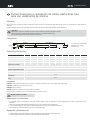
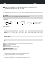
Zona fría
230 V
1 2 3
Zona calefactora
Ø 10 mm
1: Conductores de alimentación
2: Aislamiento de silicona
3: Extremo final

7130H031 Ed.07
es en
en Instructions for installing serial heating cables
with silicone insulation
Use
These instructions consider the minimum requirements to be taken into account when installing the serial heating cable so that its safety is correct.
Heating cable is indicated for evaporator drains that carry out defrosting by means of electrical resistance
Attention!
Installation, checking and connection of the power supply should be carried out by qualified staff.
Heating cable functioning must be associated with electric defrosting.
Maximum connection time must not exceed 30 minutes.
Composition
Technical specifications
Installation
AVOID sharp edges, excessive mechanical stress, twisting it, crushing it, standing on it or fitting it on any type of load.
AVOID the cable bending radius being under 10 m
AVOID it crossing or touching.
AVOID it being exposed to products that might damage its insulation.
When the cable is installed in a metal pipe, it should be earthed.
The cable should not be cut
Power supply and protections
ŸThe electrical installation of the power supply of the heating circuit should meet current regulations and standards for the environment and characteristics of the
facility.
ŸEach heating circuit should be powered by a line with the corresponding protections.
ŸThe heating area should be installed so that is protected against direct or indirect contacts.
ŸA leakage circuit-breaker with a sensitivity of 30 mA should be used.
Repairs and maintenance
ŸThe heating cable cannot be repaired. The heating cable should be replaced by another if it is damaged.
ŸRegularly check the correct operation of the electrical protections.
Reference
AKO-71370
AKO-71371
AKO-71372
AKO-71373
AKO-71374
AKO-71375
AKO-71376
AKO-71377
AKO-71378
AKO-71379
Power (± 7 %) at 230 V (W)
50
65
75
100
150
200
250
300
350
400
Power (W/m)
50
50
50
50
50
50
50
50
50
50
Current (A)
0,22
0,28
0,33
0,43
0,65
0,87
1,09
1,3
1,3
1,3
Length heating area (mm)
1000
1300
1500
2000
3000
4000
5000
6000
7000
8000
Length cold area (mm)
1000
Operating temperature range
-50 ºC / 25 ºC
Maximum exposure temperature
(disconnected cable)
180 ºC
Power supply voltage
230 V
Minimum installation
temperature
-40 ºC
Minimum bending radius
at -40 ºC
10 mm
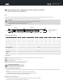
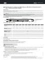
Cold area Heating area
1: Power supply conductors
2: Silicone insulation
3: End-seal
230 V
1 2 3
Ø 10 mm

7130H031 Ed.07
es en
fr Instructions pour l'installation de câbles chauffants type
série avec isolation en silicone
Utilisation
Vous trouverez dans ces instructions les conditions minimales à appliquer lors de l'installation du câble chauffant type série pour garantir votre totale sécurité.
Le câble chauffant est indiqué pour procéder aux vidanges des évaporateurs effectuant le dégivrage à l'aide de résistances électriques
Attention !
Du personnel qualifié doit se charger d'installer, de vérifier et de brancher l'équipement à l'alimentation électrique.
Le fonctionnement du câble chauffant doit être associé au cycle de dégivrage électrique.
Le temps maximal de connexion ne doit pas dépasser les 30 minutes.
Composition
Spécifications techniques
Installation
ÉVITEZ les arêtes coupantes, les efforts mécaniques excessifs, évitez de tordre le câble, de l'écraser ou de le placer sous une charge, quelle qu'elle soit.
ÉVITEZ d'avoir un rayon de courbure inférieur à 10 mm.
ÉVITEZ de le croiser et de le toucher.
ÉVITEZ de l'exposer à des produits pouvant réduire sa capacité d'isolation.
Si le câble est installé dans un tube métallique, celui-ci doit être relié à la terre.
Le câble ne doit pas être coupé.
Alimentation et protections
ŸL'installation électrique d'alimentation du circuit chauffant devra être conforme aux règlements et normes en vigueur pour l'environnement et les
caractéristiques de l'installation.
ŸChaque circuit chauffant doit être alimenté par une conduite avec les protections correspondantes.
ŸLa zone chauffante doit être installée de telle sorte qu'elle soit protégée contre les contacts directs ou indirects.
ŸUtilisez un interrupteur différentiel avec une sensibilité de 30 mA.
Réparation et entretien
ŸLe câble chauffant ne peut être réparé. Si le câble chauffant est endommagé, remplacez-le.
ŸVérifiez régulièrement le bon fonctionnement des protections électriques.
Référence
AKO-71370
AKO-71371
AKO-71372
AKO-71373
AKO-71374
AKO-71375
AKO-71376
AKO-71377
AKO-71378
AKO-71379
Puissance (± 7 %) à 230 V (W)
50
65
75
100
150
200
250
300
350
400
Puissance (W/m)
50
50
50
50
50
50
50
50
50
50
Intensité (A)
0,22
0,28
0,33
0,43
0,65
0,87
1,09
1,3
1,3
1,3
Longueur zone chauffante (mm)
1000
1300
1500
2000
3000
4000
5000
6000
7000
8000
Longueur zone froide (mm)
1000
Plage de températures de
service
-50 ºC / 25 ºC
Température maximale
d'exposition (câble débranché)
180 ºC
Tension d'alimentation
230 V
Température d'installation
minimale
-40 ºC
Rayon de courbure minimum
à -40 ºC
10 mm
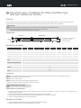
Zone froide Zone chauffante
1: Conducteurs d'alimentation
2: Isolation en silicone
3: Extrémité finale
230 V
1 2 3
Ø 10 mm

7130H031 Ed.07
es en
de Installationsanweisungen für Serien-Heizkabel
mit Silikon-Isolierung
Verwendung
Die vorliegenden Anweisungen enthalten die Mindestanforderungen, die für eine sichere Installation der Serien-Heizleitung beachtet werden müssen.
Die Heizleitung ist für den Wasserablauf von Verdampfern geeignet, die die Abtauung mittels Heizwiderständen durchführen.
Achtung!
Die Installation, Verifizierung sowie der Anschluss an die Stromversorgung muss von qualifiziertem Personal vorgenommen werden.
Der Betrieb der Heizleitung muss mit dem elektrischen Abtauungszyklus verknüpft sein.
Die maximale Einschaltdauer darf 30 Minuten nicht überschreiten.
Aufbau
Technische Daten
Installation
VERMEIDEN SIE scharfe Kanten, zu großen mechanischen Kraftaufwand, sowie ein Verdrehen und Quetschen der Leitung, treten Sie nicht darauf und legen Sie sie
auf keinerlei Last ab.
VERMEIDEN SIE einen Biegungsradius von weniger als 10 mm.
VERMEIDEN SIE, dass die Leitung gekreuzt oder berührt wird.
VERMEIDEN SIE den Kontakt der Leitung mit Produkten, die deren Isolierung beschädigen könnten.
Wird die Leitung in einem Metallrohr verlegt, so muss dieses geerdet sein.
Die Leitung darf nicht beschnitten werden
Stromversorgung und Schutzvorrichtungen
ŸDie Elektro-Installation zur Stromversorgung des Heizkreises muss die gültigen Vorschriften und Normen hinsichtlich von Umgebung und Eigenschaften der
Anlage erfüllen.
ŸJeder Heizkreis muss durch eine Leitung mit den entsprechenden Schutzvorrichtungen gespeist werden.
ŸDer Heizbereich muss so installiert werden, dass er vor direktem oder indirektem Kontakt geschützt ist.
ŸEs ist ein Differenzialschalter mit einer Empfindlichkeit von 30 mA zu verwenden.
Reparatur und Wartung
ŸDie Heizleitung darf nicht repariert werden. Ist die Heizleitung defekt oder beschädigt, so muss sie durch eine neue ausgetauscht werden.
ŸÜberprüfen Sie in regelmäßigen Abständen die korrekte Funktion der elektrischen Schutzvorrichtungen.
Referenz
AKO-71370
AKO-71371
AKO-71372
AKO-71373
AKO-71374
AKO-71375
AKO-71376
AKO-71377
AKO-71378
AKO-71379
Leistung (± 7 %) A 230 V (W)
50
65
75
100
150
200
250
300
350
400
Leistung (W/m)
50
50
50
50
50
50
50
50
50
50
Stärke (A)
0,22
0,28
0,33
0,43
0,65
0,87
1,09
1,3
1,3
1,3
Länge des Heizbereichs (mm)
1000
1300
1500
2000
3000
4000
5000
6000
7000
8000
Länge des kalten Bereichs (mm)
1000
Betriebstemperaturbereich
-50 ºC / 25 ºC
Maximale Einsatztemperatur
(bei abgetrenntem Kabel)
180 ºC
Versorgungsspannung
230 V
Min. Verlegetemperatur
-40 ºC
Min. Biegeradius bei -40 ºC
10 mm
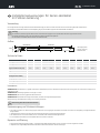
kalten Bereichs Heizbereichs
1: Versorgungsleiter
2: Silikon-Isolierung
3: Äußeres Ende
230 V
1 2 3
Ø 10 mm

7130H031 Ed.07
es en
pt Instruções para a instalação de cabos calefactores tipo
série com isolamento de silicone
Utilização
Estas instruções contemplam os requisitos mínimos a ter em consideração durante a instalação do cabo calefactor tipo série a fim de garantir uma segurança
adequada.
O cabo calefator é indicado para escoar os evaporadores que efetuam o degelo através de resistências elétricas
Atenção!
A instalação, verificação e ligação à alimentação elétrica deve ser efetuada por pessoal qualificado.
O funcionamento do cabo calefator deve estar associado ao ciclo de degelo elétrico.
O tempo máximo de ligação não deve ser superior a 30 minutos.
Composição
Dados técnicos
Instalação
EVITAR as arestas aguçadas, esforços mecânicos excessivos, torção, esmagar, pisar ou colocar sobre qualquer tipo de carga.
EVITAR que o raio de curvatura seja inferior a 10 mm.
EVITAR que se cruze ou toque.
EVITAR a exposição a produtos que possam danificar o isolamento.
Quando o cabo é instalado num tubo metálico, este deve ter ligação à terra.
O cabo não deve ser cortado
Alimentação e proteções
ŸA instalação elétrica de alimentação do circuito calefactor deverá respeitar os regulamentos e normas vigentes para o ambiente e características da instalação.
ŸCada circuito calefactor deverá ser alimentado por uma linha com as proteções correspondentes.
ŸA zona calefactora deverá ser instalada de forma a ficar protegida contra contactos diretos ou indiretos.
ŸDeverá ser utilizado um interruptor diferencial com uma sensibilidade de 30 mA.
Reparação e manutenção
ŸO cabo calefactor não pode ser reparado. Se o cabo calefactor for danificado, deve ser substituído por outro.
ŸInspecionar regularmente o correto funcionamento das proteções elétricas.
Referência
AKO-71370
AKO-71371
AKO-71372
AKO-71373
AKO-71374
AKO-71375
AKO-71376
AKO-71377
AKO-71378
AKO-71379
Potência (± 7 %) a 230 V (W)
50
65
75
100
150
200
250
300
350
400
Potência (W/m)
50
50
50
50
50
50
50
50
50
50
Intensidade (A)
0,22
0,28
0,33
0,43
0,65
0,87
1,09
1,3
1,3
1,3
Comprimento da zona de
calefação (mm)
1000
1300
1500
2000
3000
4000
5000
6000
7000
8000
Comprimento da zona fria (mm)
1000
Intervalo térmico funciona
-50 ºC / 25 ºC
Temperatura máxima de
exposição (cabo desligado)
180 ºC
Tensão de alimentação
230 V
Temperatura mínima de
instalação
-40 ºC
Raio de curvatura mínimo
a -40 ºC
10 mm
Zona fria Zona de calefaç oã
1: Condutores de alimentação
2: Isolamento de silicone
3: Extremidade final
230 V
1 2 3
Ø 10 mm

7130H031 Ed.07
es en
ru Инструкция по укладке нагревательных кабелей последовательного
типа с силиконовой изоляцией
Назначение
В данной инструкции приведены минимальные требования, которые следует соблюдать при укладке нагревательного кабеля последовательного типа с
целью обеспечения необходимой степени безопасности.
Нагревательный кабель предназначен для водоотводов испарителей, являющихся частью системы размораживания посредством электрических резисторов
Внимание!
Укладка, проверка и подключение к электропитанию должны осуществляться квалифицированным персоналом.
Работа нагревательного кабеля должна быть связана с циклом электрического размораживания.
Максимальное время включения не должно превышать 30 минут.
Конструкция
Технические характеристики
Установка
НЕ ДОПУСКАЙТЕ контакта с режущими кромками, излишних механических воздействий, не скручивайте, не сдавливайте кабель, не наступайте на него и
ничего не кладите сверху.
НЕ ДОПУСКАЙТЕ, чтобы радиус изгиба был меньше 10 мм.
НЕ ДОПУСКАЙТЕ пересечений и соприкосновений кабеля.
НЕ ДОПУСКАЙТЕ контакта с веществами, которые могут повредить изоляцию кабеля.
При укладке кабеля в металлической трубе, последняя должна быть заземлена.
Запрещается резать кабель
Электропитание и защита
ŸУстановка электропитания нагревательного контура должна соответствовать действующим правилам и стандартам в отношении охраны
окружающей среды и характеристик установки.
ŸЛиния электропитания каждого нагревательного контура должна быть оборудована соответствующими устройствами защиты.
ŸНагревательный участок кабеля должен укладываться так, чтобы обеспечить его защиту от прямых или непрямых контактов.
ŸЧувствительность используемого дифференциального выключателя должна составлять 30 мА.
Ремонт и техническое обслуживание
ŸНагревательный кабель не подлежит ремонту. Если нагревательный кабель поврежден, его следует заменить.
ŸСледует регулярно проверять правильность работы устройств электрической защиты.
Ссылка
AKO-71370
AKO-71371
AKO-71372
AKO-71373
AKO-71374
AKO-71375
AKO-71376
AKO-71377
AKO-71378
AKO-71379
Мощность (± 7%) при 230 В (Вт)
50
65
75
100
150
200
250
300
350
400
Выход (Вт/м)
50
50
50
50
50
50
50
50
50
50
Сила тока (А)
0,22
0,28
0,33
0,43
0,65
0,87
1,09
1,3
1,3
1,3
Длина нагревательного
участка (мм)
1000
1300
1500
2000
3000
4000
5000
6000
7000
8000
Длина холодного участка (мм)
1000
Диапазон рабочих температур
-50 ºC / 25 ºC
Максимальная температура
воздействия
(с отключенным кабелем)
180 ºC
Напряжение электропитания
230 B
Минимальная температура
установки
-40 ºC
Минимальный радиус изгиба
при -40 °C
10 mm
Холодный участок
230 B
1 2 3
Нагревательный участок
Ø 10 mm
1: Проводники электропитания
2: Силиконовая изоляция
3: Конец
357130031 REV.06 2023
AKO ELECTROMECÁNICA , S.A.L.
Avda. Roquetes, 30-38
08812 Sant Pere de Ribes.•
Barcelona Spain.•
www.ako.com
Nos reservamos el derecho de suministrar materiales que pudieran diferir levemente de los descritos en nuestras Hojas Técnicas. Información actualizada en nuestra web.
We reserve the right to supply materials that might vary slightly to those described in our Technical Sheets. Updated information is available on our website.
Nous nous réservons le droit de fournir du matériel différant légèrement de celui décrit dans nos Feuilles techniques. Informations mises à jour sur notre site web.
Wir behalten uns das Recht vor, Materialien zu liefern, die leicht von den in unseren Datenblättern beschriebenen Materialien abweichen können. Aktuelle Informationen finden Sie auf unserer Webseite.
Reservamos o direito de fornecermateriais que possamserligeiramente diferentes da descrição das nossas FichasTécnicas. Informação atualizada na nossa página
Мы оставляем за собой право на поставку материалов, которые могут несколько отличаться от описанных в наших технических условиях. Обновленную информацию можно получить на нашем вебсайте.
-
 1
1
-
 2
2
-
 3
3
-
 4
4
-
 5
5
-
 6
6


in anderen Sprachen
- français: AKO heating cables Mode d'emploi
- español: AKO heating cables Instrucciones de operación
- português: AKO heating cables Instruções de operação
Sonstige Unterlagen
-
Lego 71377 Super Mario Building Instructions
-
-
-
-
Danfoss heating cables Bedienungsanleitung
-
Princess 112256 Bedienungsanleitung
-
Wacker Neuson AR 36/3,6/480 Benutzerhandbuch
-