CARLO GAVAZZI WM15 Benutzerhandbuch
- Kategorie
- Messen, Testen
- Typ
- Benutzerhandbuch
Dieses Handbuch eignet sich auch für

WM15
Power analyser for three-phase systems
USER MANUAL

2 WM15 - User manual | CARLO GAVAZZI Controls SpAWM15 - User manual | CARLO GAVAZZI Controls SpA
Summary
WM15 5
Preliminary remarks 5
Description 5
Available versions 6
UCS (Universal Conguration Software) 7
Use of WM15 8
Preliminary remarks 8
SETTINGS menu display 8
INFO menu display 8
RESET menu display 9
Measurement page display 9
Information and warnings 9
Commissioning 10
Preliminary settings 10
MID SETTINGS menu 10
QUICK SETUP menu 11
WIRING CHECK menu 12
Performing operations in WM15 13
Performing operations in the measurement pages 13
Performing operations in the SETTINGS menu 13
Performing operations in the INFO menu 13
Performing operations in the RESET menu 13
Menu description 14
Measurement pages 14
SETTINGS menu 16
INFO menu 16
RESET menu 17
Things you should be aware of 18
Preliminary remarks 18
Variables 18
Alarm types 18
Average value calculation (dmd) 19
Integration interval 19
Home page 20
Backlight 20
Screensaver 20
Page lter 20
Restoring the settings using the RESET menu 20
Restoring the settings using the reset button 20
Preliminary remarks 21
Display check 21
Check from UCS software or UCS Mobile 21
Virtual correction from UCS software or UCS Mobile 21


4 WM15 - User manual | CARLO GAVAZZI Controls SpAWM15 - User manual | CARLO GAVAZZI Controls SpA
Information property
Copyright © 2019, CARLO GAVAZZI Controls SpA
All rights reserved in all countries.
CARLO GAVAZZI Controls SpA reserves the right to apply modifications or make improvements to the relative documentation without the
obligation of advance notice.
Safety messages
The following section describes the warnings related to user and device safety included in this document:
NOTICE: indicates obligations that if not observed may lead to damage to the device.
CAUTION! Indicates a risky situation which, if not avoided, may cause data loss.
IMPORTANT: provides essential information on completing the task that should not be neglected.
General warnings
This manual is an integral part of the product and accompanies it for its entire working life. It should be consulted for all situations
tied to configuration, use and maintenance. For this reason, it should always be accessible to operators.
NOTICE: no one is authorized to open the analyzer or remove the MABC module. This operation is reserved exclusively for CARLO
GAVAZZI technical service personnel.
Protection may be impaired if the instrument is used in a manner not specified by the manufacturer.
Service and warranty
In the event of malfunction, fault, requests for information or to purchase accessory modules, contact the CARLO GAVAZZI branch or
distributor in your country.
Installation and use of analyzers other than those indicated in the provided instructions and removal of the MABC module void the warranty.
Download
This manual www.productselection.net/MANUALS/UK/WM15_im_use.pdf
Installation instructions - WM15 www.productselection.net/MANUALS/UK/WM15_im_inst.pdf
UCS software www.productselection.net/Download/UK/ucs.zip

5WM15 - User manual | CARLO GAVAZZI Controls SpAWM15 - User manual | CARLO GAVAZZI Controls SpA
WM15
Introduction
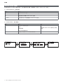
WM15 is a power analyser for single-, two- and three-phase systems.
Depending on the model, WM15 is equipped with a static output (pulse or alarm) or with a static output and a Modbus RTU
static communication port.
The self-powered version can be installed on systems with voltage up to 415 V L-L, while the version with auxiliary power sup-
ply can be installed on systems with voltage up to 600 V L-L.
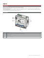
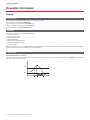
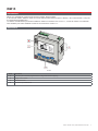
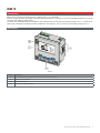
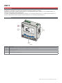
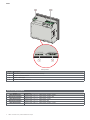
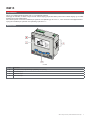
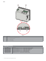
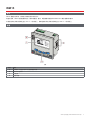
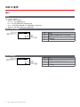
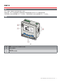
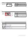
Description
Front
Part Description
A Optical port for easy programming and diagnostics through Optoprog
B Matrix LCD display
C Mechanical keys
D Grooves for side brackets

6 WM15 - User manual | CARLO GAVAZZI Controls SpAWM15 - User manual | CARLO GAVAZZI Controls SpA
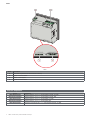
WM15
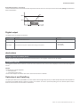
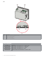
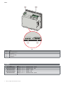
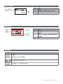
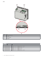
Rear
Part Description
A Power supply (version with auxiliary supply)
B Three-phase voltage inputs
C RS485 + digital output
D Three-phase current inputs
Available versions
Code Description
WM1596AV53XOSX Self power supply, 415 V L-L. Digital output and RS485, not MID
WM1596AV53XOSPFB Self power supply, 415 V L-L. Digital output and RS485, MID
WM1596AV53XOXX Self power supply, 415 V L-L. Digital output, not MID
WM1596AV53XOXPFB Self power supply, 415 V L-L. Digital output, MID
WM1596AV53HOSX Auxiliary supply, 600 V L-L. Digital output and RS485, not MID

7WM15 - User manual | CARLO GAVAZZI Controls SpAWM15 - User manual | CARLO GAVAZZI Controls SpA
WM15
UCS (Universal Conguration Software)
UCS is available in desktop and mobile versions.
It may connect to WM15 via RS485 (RTU protocol, desktop version only) or through OptoProg (via Bluetooth).
UCS allows to:
• set up the WM15 unit (online or offline);
• display the system state for diagnostic and setup verification purposes
Overview of the UCS functions:
• Setting up the system with WM15 connected (online setup)
• Defining the setup with WM15 non connected, then applying it at a later time (offline setup)
• Displaying the main measurements
• Displaying the state of inputs and outputs
• Displaying the state of the alarms
• Recording the measurements of selected variables (UCS Desktop version only)
• Displaying the quick help on installing WM15 and connecting with OptoProg (UCS Mobile version only)

8 WM15 - User manual | CARLO GAVAZZI Controls SpAWM15 - User manual | CARLO GAVAZZI Controls SpA
Use of WM15
Interface
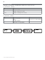
Introduction
WM15 is organised into two menus:
• Main menu, divided into three sub-menus:
» SETTINGS: pages allowing to set the parameters
» INFO: pages displaying general information and the set parameters
» RESET: pages allowing to reset the partial counters and the dmd calculation, or to restore the factory settings
• Measurement pages: pages allowing to display the meters and the other electrical variables
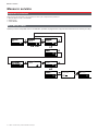
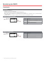
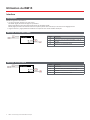
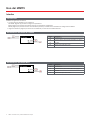
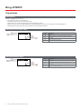
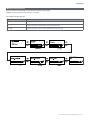
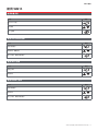
SETTINGS menu display
Part
Description
A
Menu title
B
Sub-menu title, see “SETTINGS menu” on page 16
C
Parameter
D
Current parameter information
INFO menu display
Part
Description
A
Menu title
B
Sub-menu title, see “INFO menu” on page 17
C
Parameter
D
Current parameter information

9WM15 - User manual | CARLO GAVAZZI Controls SpAWM15 - User manual | CARLO GAVAZZI Controls SpA
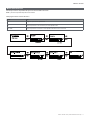
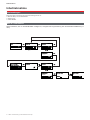
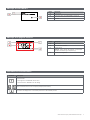
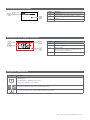
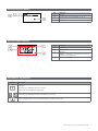
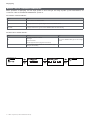
Measurement page display
RESET menu display
Part
Description
A
Menu title
B
Sub-menu title, see “RESET menu” on page 17
C
Parameter
Part
Description
A
Variable type
B
measured values/data
C
unit of measurement
Note: for the “power factor” the unit indicates whether the
value is inductive (L) or capacitive (C)
D
information and diagnostics
Information and warnings
Symbol
Description
Alarm icon:
• blinking icon + ALARM ON: alarm active
• steadily ON icon + WIRING: wiring error
Serial or optical communication state (reception / transmission)
Virtual wiring correction: the terminal-phase association was modified by UCS

10 WM15 - User manual | CARLO GAVAZZI Controls SpAWM15 - User manual | CARLO GAVAZZI Controls SpA
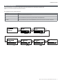
Commissioning
Commissioning
Preliminary settings
At switch-on, the device displays three preliminary setting menus:
• MID SETTINGS, for MID models only
• QUICK SETUP
• CHECK WIRING
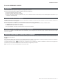
MID SETTINGS menu
This procedure, only available in MID models, allows to program the current transformer ratio (CT ratio).

11WM15 - User manual | CARLO GAVAZZI Controls SpAWM15 - User manual | CARLO GAVAZZI Controls SpA
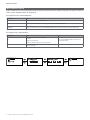
Commissioning
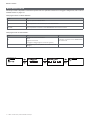
QUICK SETUP menu
This procedure is available when the instrument is switched on for the first time.
Note: the available parameters depend on the model.
In the “QUICK SETUP?” starting page
Select... To...
YES run the QUICK SETUP procedure
NO skip the procedure and no longer display the QUICK SETUP menu
NEXT TIME skip the procedure and display the QUICK SETUP menu at the next switch-on

WM15 - User manual | CARLO GAVAZZI Controls SpA12 WM15 - User manual | CARLO GAVAZZI Controls SpA
Commissioning
WIRING CHECK menu
This procedure is available if the set system is 3P+N, and allows to check and correct the connections, see “WIRING CHECK
function” on page 21.
In the “CHECK WIRING?” starting page
Select... To...
YES run the WIRING CHECK procedure
NO skip the procedure and no longer display the WIRING CHECK menu
NEXT TIME skip the procedure and display the WIRING CHECK menu at the next switch-on
In the “SHOW AGAIN?” end page
Select... To... And...
YES
correct the error detected by WM15.
Actions:
• switch off the instrument
• correct the wiring (follow the graphical indications)
display the WIRING CHECK menu again for the
final check
NO
No longer display the menu (WM15 has detected no wiring
errors)
-

13
WM15 use
WM15 - User manual | CARLO GAVAZZI Controls SpAWM15 - User manual | CARLO GAVAZZI Controls SpA
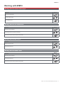
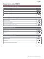
Working with WM15
Working with the measurement pages
Operation
Button
Return to the Home page
Scroll through the pages
/
Enter the Main menu
Working with the SETTINGS menu
Operation
Button
Return/Cancel the operation
Scroll through the menu, edit the parameters
/
Enter the sub-menu to edit and confirm the operation
Working with the INFO menu
Operation
Button
Return to the main menu
Scroll through the menu
/
Working with the RESET menu
Operation
Button
Return/Cancel the operation
Scroll through the menu
/
Enter the sub-menu to edit and confirm the operation

14
WM15 use
WM15 - User manual | CARLO GAVAZZI Controls SpA
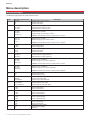
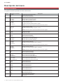
Menu description
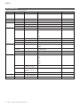
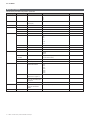
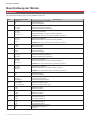
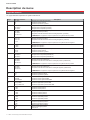
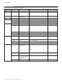
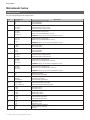
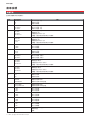
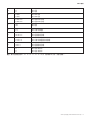
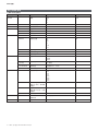
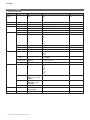
Measurement pages
The displayed pages depend on the selected system.
Page Displayed measurements Description
1
TOT kWh
kW
PF
Imported active energy (TOTAL)
System active power
System power factor
2
TOT kWh
TOT kvarh+
TOT kvarh-
Imported active energy (TOTAL)
Imported reactive energy (TOTAL)
Exported reactive energy (TOTAL)
3
TOT kWh
TOT kVAh
TOT hh:mm+
Imported active energy (TOTAL)
Apparent energy (TOTAL)
Positive energy run hour meter* (TOTAL)
*NOTE: it increases when the active system power is positive.
4
kWh- TOT
kVAh TOT
h- TOT
Exported active energy (TOTAL)
Apparent energy (TOTAL)
Negative energy run hour meter* (TOTAL)
*NOTE: it increases when the active system power is negative.
5
L1 kWh
L2 kWh
L3 kWh
Active energy phase 1
Active energy phase 2
Active energy phase 3
6
PAR kWh
kW sys
PF sys
Imported active energy (PARTIAL)
System active power
System power factor
7
PAR kWh
PAR kvarh+
PAR kvarh-
Imported active energy (PARTIAL)
Imported reactive energy (PARTIAL)
Exported reactive energy (PARTIAL)
8
PAR kWh+
PAR kVAh
PAR hh:mm+
Imported active energy (PARTIAL)
Apparent energy (PARTIAL)
Positive energy run hour meter* (PARTIAL)
*NOTE: it increases when the active system power is positive.
9
PAR kWh-
PAR kVAh
PAR hh:mm-
Exported active energy (PARTIAL)
Apparent energy (PARTIAL)
Negative energy run hour meter* (PARTIAL)
*NOTE: it increases when the active system power is negative.
10
kW
kvar
kVA
System active power
System reactive power
System apparent power
11
kW
kW DMD
kW DMD MAX
System active power
System active power DMD
System active power MAX DMD
12
kVA sys
kVA sys DMD
kVA sys DMD max
System apparent power
System apparent power DMD
System apparent power MAX DMD
13
L1 kW
L2 kW
L3 kW
Phase 1 active power
Phase 2 active power
Phase 3 active power
14
L1 kvar
L2 kvar
L3 kvar
Phase 1 reactive power
Phase 2 reactive power
Phase 3 reactive power
15
L1 kVA
L2 kVA
L3 kVA
Phase 1 apparent power
Phase 2 apparent power
Phase 3 apparent power
16
L1 PF
L2 PF
L3 PF
Phase 1 power factor
Phase 2 power factor
Phase 3 power factor
17
L-N V
L-L V
Hz
System line-neutral voltage
System line-line voltage
Frequency

15
WM15 use
WM15 - User manual | CARLO GAVAZZI Controls SpA
Note: pages 1, 10, 13, 16, 17, 21, 22 and 26 are included in the default filter; see “Page filter” on page 20
18
L1 A
L2 A
L3 A
Phase 1 current
Phase 2 current
Phase 3 current
19
L1 A DMD
L2 A DMD
L3 A DMD
Phase 1 DMD current
Phase 2 DMD current
Phase 3 DMD current
20
L1 A DMD max
L2 A DMD max
L3 A DMD max
Phase 1 current DMD MAX
Phase 2 current DMD MAX
Phase 3 current DMD MAX
21
L1-N V
L2-N V
L3-N V
Phase 1 voltage
Phase 2 voltage
Phase 3 voltage
22
L1-2 V
L2-3 V
L3-1 V
Phase 1-phase 2 voltage
Phase 2-phase 3 voltage
Phase 3-phase 1 voltage
23
L1-N THD V %
L2-N THD V %
L3-N THD V %
THD of phase 1 voltage
THD of phase 2 voltage
THD of phase 3 voltage
24
L1-2 THD V %
L2-3 THD V %
L3-1 THD V %
THD of phase 1-phase2 voltage
THD of phase2-phase3 voltage
THD of phase3-phase1 voltage
25
L1 THD I %
L2 THD I %
L3 THD I %
THD of phase 1 current
THD of phase 2 current
THD of phase 3 current
26
V L-L sys
L1 A
L2 A
L3 A
System Phase-phase voltage
Phase 1 current (bar graph)
Phase 2 current (bar graph)
Phase 3 current (bar graph)

16
WM15 use
WM15 - User manual | CARLO GAVAZZI Controls SpA
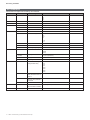
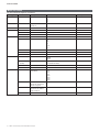
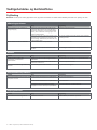
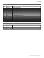
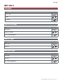
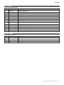
SETTINGS menu
This menu allows to set the parameters.
Page title Sub-menu Description Values Default values
SYSTEM - System 3P+N
3P
2P
1P
3P+N
CT RATIO - (CT) current transformer ratio 1.0 to 2000 1.0
DMD INTERVAL - dmd interval 1 to 60 min 15 min
RS485 ADDRESS Address 1 to 247 1
BAUDRATE Baudrate 9.6 to 115.2 kbps 9.6 kbps
PARITY Parity NO/EVEN NO
ALARM ENABLE Enable YES/NO NO
VARIABLE Monitored variable kW
kVA
kvar
PF
A
V L-N
V L-L
kW
SET POINT 1 Activation threshold -15000 to 15000 0.00
SET POINT 2 Deactivation threshold -15000 to 15000 0.00
ACTIVATION DELAY Activation delay 0 to 3600 s 0
DIGITAL OUTPUT FUNCTION Function DISABLED
ALARM
PULSE
DISABLED
OUTPUT STATUS
(ALARM)
Output state NO (normally open)
NC (normally closed)
NO
PULSE WEIGHT Pulses weight 0.001 to 10 kWh/pulse 1
PULSE DURATION Pulse duration 30/100 ms 30 ms
DISPLAY BACKLIGHT TIME Timer for backlight switch-off ALWAYS ON
1 min
2 min
5 min
10 min
20 min
30 min
60 min
ALWAYS ON
SCREENSAVER Screensaver enabling, see
“Screensaver” on page 20
ON/OFF ON
PAGE FILTER Measurement page lter
enabling, see “Page lter” on
page 20
ON/OFF OFF
WIRING CHECK Icon enabling ON/OFF ON
PASSWORD Password enabling for the
SETTINGS and RESET menu
0000 (not protected) to 9999 0000 (NOT PROTECTED)
EXIT - Exit - -

17
WM15 use
WM15 - User manual | CARLO GAVAZZI Controls SpA
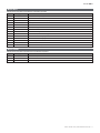
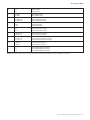
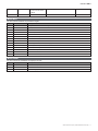
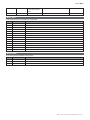
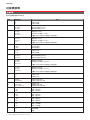
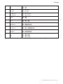
INFO menu
This menu allows to display the set parameters.
Page Page title Description
1 WIRING CHECK Display of wiring check icon enabled/disabled
2 SYSTEM System type
3 CT RATIO (CT) current transformer ratio
4 LED PULSE Pulses weight
5 DMD INTERVAL dmd interval
6 RS485 Address, baudrate, parity
7 ALARM Alarm function
8 DIGITAL OUTPUT Digital output function
9 DISPLAY Backlight, screensaver, page lter and WIRING CHECK function
10 V CONNECTIONS Terminal- phase association for voltage inputs
11 I CONNECTIONS Terminal-phase association for current inputs
12 CHECKSUM FW Checksum for MID certification
13 SERIAL NUMBER Serial number
14 SECONDARY ADDR M-Bus secondary address for use with VMU-B
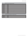
RESET menu
This menu allows to reset the following settings:
Page Page title Description
1 PARTIAL It resets the partial meters
2 DMD AND MAX It resets the dmd calculation
3 FACTORY RESET It restores the factory settings

18
Essential information
WM15 - User manual | CARLO GAVAZZI Controls SpA
Essential information
Alarms
Introduction
WM15 manages a measured variable alarm. To set the alarm, define:
• the variable to be monitored (VARIABLE)
• alarm activation threshold value (SET POINT 1)
• alarm deactivation threshold value (SET POINT 2)
• alarm activation delay (ACTIVATION DELAY)
Variables
The unit can monitor one of the following variables:
• system active power
• system apparent power
• system reactive power
• system power factor
• phase-neutral voltage (OR logic)
• phase-phase voltage (OR logic)
• current (OR logic)
Note: if you select a current or a voltage, WM15 simultaneously monitors all the phases available in the set measurement system and triggers
the alarm when at least one of the phases is in alarm (OR logic)
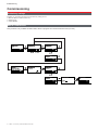
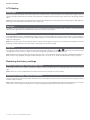
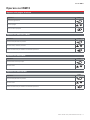
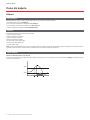
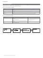
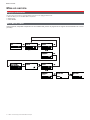
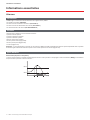
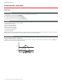
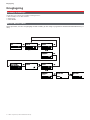
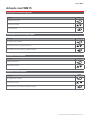
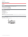
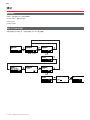
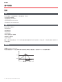
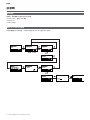
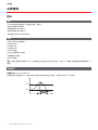
Alarm types
Up alarm (Set point 1 ≥ Set point 2)
The alarm activates when the monitored variable exceeds the Set 1 value for a time equal to the activation delay (Delay) and deactivates
when the values drops below Set 2.
(s)
ON
Set 1
Set 2
Delay

19
Essential information
WM15 - User manual | CARLO GAVAZZI Controls SpA
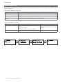
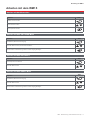
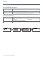
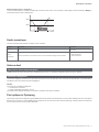
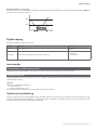
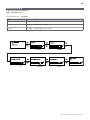
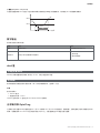
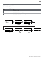
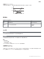
Down alarm (Set point 1 < Set point 2)
The alarm activates when the monitored variable drops below the Set 1 value for a time equal to the activation delay (Delay) and deactivates
when it exceeds Set 2.
(s)
ON
Set 2
Set 1
Delay
Digital output
The digital output can perform two functions:
Function Description Parameters
Alarm Output associated with the alarm Output state when no alarm is active
Pulse output Pulse transmission output for imported active energy consumptions.
• Pulse weight
• Pulse duration
dmd values
Average value calculation (dmd)
WM15 calculates the average values of the electrical variables within a set integration interval (15 min by default).
Integration interval
The integration interval starts at switch-on or when the reset command is issued. The first value is displayed at the end of the first integration
interval.
Example
The following is a sample integration:
• reset at 10:13:07
• set integration time: 15 min.
The first value displayed at 10:28:07 refers to the interval from 10:13:07 to 10:28:07.
Optical port and OptoProg
The optical port allows to set up the WM15 unit and to read the data through UCS (from PC) or mobile UCS (da smartphone Android) without
connecting to the RS485 network to which the analyser is connected. You need to purchase OptoProg, the Carlo Gavazzi optical interface
device for communication via micro USB or via Bluetooth.

20
Essential information
WM15 - User manual | CARLO GAVAZZI Controls SpA
LCD display
Home page
The unit may display the default measurement pages when the Home button is pressed (starting from any measurement page) or after no
operation has been performed for five minutes, if the screensaver is enabled and the screensaver type is set by UCS to “Home page” (default
value).
Notes: if you select a page that is not available in the set system, the unit displays as its home page the first available page. In MID models the
home page cannot be changed and displays the active energy meter.
Backlight
The WM15 unit is equipped with a backlight system. You can set whether the backlight shall always be ON or whether it should automatically
switch off after a given interval has elapsed since a button was pressed (1 to 60 minutes).
Screensaver
If the SCREENSAVER function is enabled (default setting), after 5 minutes have elapsed since a button was pressed the unit will display the
home page if the screensaver type is “Home page” (default setting), or it shall activate the slideshow function, which displays the selected
pages on a rotating basis
Notes: the screensaver type and the slideshow function with the relevant pages can only be set up through the UCS software or the UCS
Mobile app. In MID models the screensaver setting is “Homepage” and cannot be changed.
Page lter
The page filter makes it easier to use and browse the measurement pages. When you use the / buttons, the unit shall only display
the pages you are most interested in, which can be selected through the UCS software or the UCS Mobile app.
Note: to display all the pages without using the UCS software or app, you can disable the page filter from the SETTINGS MENU (DISPLAY →
PAGE FILTER → OFF). By default, the pages included in the filter are: 1, 10, 13, 16, 17, 21, 22, 26, see “Measurement pages” on page 14.
Restoring the factory settings
Restoring the settings using the RESET menu
From the RESET menu you can restore all the factory settings. At start-up the QUICK SET-UP and WIRING CHECK menu shall be available
again.
Notes: meters are not reset. In MID models you cannot reset the CT current transformer ratio (CT RATIO).
Restoring the settings using the reset button
Press for at least five seconds the reset button (located near the current inputs) to access the menu, restore all the factory settings and reset
all meters (total and partial).
Note: in MID models the reset can only be performed if the energy meter has not exceeded 1 kWh. Before sealing the terminal, you can then
correct any CT current transformer setting errors (CT ratio), reactivating the MID programming menu at the next switch-on.
Seite wird geladen ...
Seite wird geladen ...
Seite wird geladen ...
Seite wird geladen ...
Seite wird geladen ...
Seite wird geladen ...
Seite wird geladen ...
Seite wird geladen ...
Seite wird geladen ...
Seite wird geladen ...
Seite wird geladen ...
Seite wird geladen ...
Seite wird geladen ...
Seite wird geladen ...
Seite wird geladen ...
Seite wird geladen ...
Seite wird geladen ...
Seite wird geladen ...
Seite wird geladen ...
Seite wird geladen ...
Seite wird geladen ...
Seite wird geladen ...
Seite wird geladen ...
Seite wird geladen ...
Seite wird geladen ...
Seite wird geladen ...
Seite wird geladen ...
Seite wird geladen ...
Seite wird geladen ...
Seite wird geladen ...
Seite wird geladen ...
Seite wird geladen ...
Seite wird geladen ...
Seite wird geladen ...
Seite wird geladen ...
Seite wird geladen ...
Seite wird geladen ...
Seite wird geladen ...
Seite wird geladen ...
Seite wird geladen ...
Seite wird geladen ...
Seite wird geladen ...
Seite wird geladen ...
Seite wird geladen ...
Seite wird geladen ...
Seite wird geladen ...
Seite wird geladen ...
Seite wird geladen ...
Seite wird geladen ...
Seite wird geladen ...
Seite wird geladen ...
Seite wird geladen ...
Seite wird geladen ...
Seite wird geladen ...
Seite wird geladen ...
Seite wird geladen ...
Seite wird geladen ...
Seite wird geladen ...
Seite wird geladen ...
Seite wird geladen ...
Seite wird geladen ...
Seite wird geladen ...
Seite wird geladen ...
Seite wird geladen ...
Seite wird geladen ...
Seite wird geladen ...
Seite wird geladen ...
Seite wird geladen ...
Seite wird geladen ...
Seite wird geladen ...
Seite wird geladen ...
Seite wird geladen ...
Seite wird geladen ...
Seite wird geladen ...
Seite wird geladen ...
Seite wird geladen ...
Seite wird geladen ...
Seite wird geladen ...
Seite wird geladen ...
Seite wird geladen ...
Seite wird geladen ...
Seite wird geladen ...
Seite wird geladen ...
Seite wird geladen ...
Seite wird geladen ...
Seite wird geladen ...
Seite wird geladen ...
Seite wird geladen ...
Seite wird geladen ...
Seite wird geladen ...
Seite wird geladen ...
Seite wird geladen ...
Seite wird geladen ...
Seite wird geladen ...
Seite wird geladen ...
Seite wird geladen ...
Seite wird geladen ...
Seite wird geladen ...
Seite wird geladen ...
Seite wird geladen ...
Seite wird geladen ...
Seite wird geladen ...
Seite wird geladen ...
Seite wird geladen ...
Seite wird geladen ...
Seite wird geladen ...
Seite wird geladen ...
Seite wird geladen ...
Seite wird geladen ...
Seite wird geladen ...
Seite wird geladen ...
Seite wird geladen ...
Seite wird geladen ...
Seite wird geladen ...
Seite wird geladen ...
Seite wird geladen ...
Seite wird geladen ...
Seite wird geladen ...
Seite wird geladen ...
Seite wird geladen ...
Seite wird geladen ...
Seite wird geladen ...
Seite wird geladen ...
Seite wird geladen ...
Seite wird geladen ...
Seite wird geladen ...
Seite wird geladen ...
Seite wird geladen ...
Seite wird geladen ...
Seite wird geladen ...
Seite wird geladen ...
Seite wird geladen ...
Seite wird geladen ...
Seite wird geladen ...
Seite wird geladen ...
Seite wird geladen ...
Seite wird geladen ...
Seite wird geladen ...
Seite wird geladen ...
Seite wird geladen ...
Seite wird geladen ...
Seite wird geladen ...
Seite wird geladen ...
Seite wird geladen ...
Seite wird geladen ...
Seite wird geladen ...
Seite wird geladen ...
Seite wird geladen ...
Seite wird geladen ...
Seite wird geladen ...
Seite wird geladen ...
Seite wird geladen ...
Seite wird geladen ...
Seite wird geladen ...
Seite wird geladen ...
Seite wird geladen ...
Seite wird geladen ...
Seite wird geladen ...
Seite wird geladen ...
Seite wird geladen ...
Seite wird geladen ...
Seite wird geladen ...
Seite wird geladen ...
Seite wird geladen ...
Seite wird geladen ...
Seite wird geladen ...
Seite wird geladen ...
Seite wird geladen ...
Seite wird geladen ...
Seite wird geladen ...
Seite wird geladen ...
Seite wird geladen ...
-
 1
1
-
 2
2
-
 3
3
-
 4
4
-
 5
5
-
 6
6
-
 7
7
-
 8
8
-
 9
9
-
 10
10
-
 11
11
-
 12
12
-
 13
13
-
 14
14
-
 15
15
-
 16
16
-
 17
17
-
 18
18
-
 19
19
-
 20
20
-
 21
21
-
 22
22
-
 23
23
-
 24
24
-
 25
25
-
 26
26
-
 27
27
-
 28
28
-
 29
29
-
 30
30
-
 31
31
-
 32
32
-
 33
33
-
 34
34
-
 35
35
-
 36
36
-
 37
37
-
 38
38
-
 39
39
-
 40
40
-
 41
41
-
 42
42
-
 43
43
-
 44
44
-
 45
45
-
 46
46
-
 47
47
-
 48
48
-
 49
49
-
 50
50
-
 51
51
-
 52
52
-
 53
53
-
 54
54
-
 55
55
-
 56
56
-
 57
57
-
 58
58
-
 59
59
-
 60
60
-
 61
61
-
 62
62
-
 63
63
-
 64
64
-
 65
65
-
 66
66
-
 67
67
-
 68
68
-
 69
69
-
 70
70
-
 71
71
-
 72
72
-
 73
73
-
 74
74
-
 75
75
-
 76
76
-
 77
77
-
 78
78
-
 79
79
-
 80
80
-
 81
81
-
 82
82
-
 83
83
-
 84
84
-
 85
85
-
 86
86
-
 87
87
-
 88
88
-
 89
89
-
 90
90
-
 91
91
-
 92
92
-
 93
93
-
 94
94
-
 95
95
-
 96
96
-
 97
97
-
 98
98
-
 99
99
-
 100
100
-
 101
101
-
 102
102
-
 103
103
-
 104
104
-
 105
105
-
 106
106
-
 107
107
-
 108
108
-
 109
109
-
 110
110
-
 111
111
-
 112
112
-
 113
113
-
 114
114
-
 115
115
-
 116
116
-
 117
117
-
 118
118
-
 119
119
-
 120
120
-
 121
121
-
 122
122
-
 123
123
-
 124
124
-
 125
125
-
 126
126
-
 127
127
-
 128
128
-
 129
129
-
 130
130
-
 131
131
-
 132
132
-
 133
133
-
 134
134
-
 135
135
-
 136
136
-
 137
137
-
 138
138
-
 139
139
-
 140
140
-
 141
141
-
 142
142
-
 143
143
-
 144
144
-
 145
145
-
 146
146
-
 147
147
-
 148
148
-
 149
149
-
 150
150
-
 151
151
-
 152
152
-
 153
153
-
 154
154
-
 155
155
-
 156
156
-
 157
157
-
 158
158
-
 159
159
-
 160
160
-
 161
161
-
 162
162
-
 163
163
-
 164
164
-
 165
165
-
 166
166
-
 167
167
-
 168
168
-
 169
169
-
 170
170
-
 171
171
-
 172
172
-
 173
173
-
 174
174
-
 175
175
-
 176
176
-
 177
177
-
 178
178
-
 179
179
-
 180
180
-
 181
181
-
 182
182
-
 183
183
-
 184
184
-
 185
185
-
 186
186
-
 187
187
-
 188
188
-
 189
189
-
 190
190
-
 191
191
-
 192
192


CARLO GAVAZZI WM15 Benutzerhandbuch
- Kategorie
- Messen, Testen
- Typ
- Benutzerhandbuch
- Dieses Handbuch eignet sich auch für
in anderen Sprachen
- English: CARLO GAVAZZI WM15 User manual
- français: CARLO GAVAZZI WM15 Manuel utilisateur
- español: CARLO GAVAZZI WM15 Manual de usuario
- italiano: CARLO GAVAZZI WM15 Manuale utente
- dansk: CARLO GAVAZZI WM15 Brugermanual
Verwandte Artikel
-
CARLO GAVAZZI WM1596AV53XOSX Bedienungsanleitung
-
-
-
CARLO GAVAZZI EM530DINAV53XM1X Bedienungsanleitung
-
-
-
-
-
-

