Yamaha DXS15XLF Bedienungsanleitung
- Kategorie
- Audio-Equalizer
- Typ
- Bedienungsanleitung

Owner’s Manual
Bedienungsanleitung
Mode d’emploi
Manual de instrucciones
Manual do Proprietário
JA
RU
KO
IT
PT
ES
FR
DE
EN
Manuale di istruzioni
Руководство пользователя
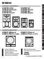
POWERED SPEAKER SYSTEM
POWERED SUBWOOFER
POWERED LOUDSPEAKER

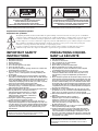
Explanation of Graphical Symbols
Explication des symboles
The lightning flash with arrowhead symbol within an equilateral triangle is intended to alert the user to the presence of uninsulated
“dangerous voltage” within the product’s enclosure that may be of sufficient magnitude to constitute a risk of electric shock to persons.
L’éclair avec une flèche à l’intérieur d’un triangle équilatéral est destiné à attirer l’attention de l’utilisateur sur la présence d’une
« tension dangereuse » non isolée à l’intérieur de l’appareil, pouvant être suffisamment élevée pour constituer un risque d’électrocution.
The exclamation point within an equilateral triangle is intended to alert the user to the presence of important operating and
maintenance (servicing) instructions in the literature accompanying the product.
Le point d’exclamation à l’intérieur d’un triangle équilatéral est destiné à attirer l’attention de l’utilisateur sur la présence
d’instructions importantes sur l’emploi ou la maintenance (réparation) de l’appareil dans la documentation fournie.
IMPORTANT SAFETY
INSTRUCTIONS
1 Read these instructions.
2 Keep these instructions.
3 Heed all warnings.
4 Follow all instructions.
5 Do not use this apparatus near water.
6 Clean only with dry cloth.
7 Do not block any ventilation openings. Install in accordance with
the manufacturer’s instructions.
8 Do not install near any heat sources such as radiators, heat
registers, stoves, or other apparatus (including amplifiers) that
produce heat.
9 Do not defeat the safety purpose of the polarized or grounding-
type plug. A polarized plug has two blades with one wider than the
other. A grounding type plug has two blades and a third grounding
prong. The wide blade or the third prong are provided for your
safety. If the provided plug does not fit into your outlet, consult an
electrician for replacement of the obsolete outlet.
10 Protect the power cord from being walked on or pinched
particularly at plugs, convenience receptacles, and the point
where they exit from the apparatus.
11 Only use attachments/accessories specified by the manufacturer.
12 Use only with the cart, stand, tripod, bracket, or
table specified by the manufacturer, or sold with
the apparatus. When a cart is used, use caution
when moving the cart/apparatus combination to
avoid injury from tip-over.
13 Unplug this apparatus during lightning storms
or when unused for long periods of time.
14 Refer all servicing to qualified service personnel. Servicing is
required when the apparatus has been damaged in any way, such
as power-supply cord or plug is damaged, liquid has been spilled
or objects have fallen into the apparatus, the apparatus has been
exposed to rain or moisture, does not operate normally, or has
been dropped.
(UL60065_03)
PRÉCAUTIONS CONCER-
NANT LA SÉCURITÉ
1 Lire ces instructions.
2 Conserver ces instructions.
3 Tenir compte de tous les avertissements.
4 Suivre toutes les instructions.
5 Ne pas utiliser ce produit à proximité d’eau.
6 Nettoyer uniquement avec un chiffon propre et sec.
7 Ne pas bloquer les orifices de ventilation. Installer l’appareil
conformément aux instructions du fabricant.
8 Ne pas installer l’appareil à proximité d’une source de chaleur
comme un radiateur, une bouche de chaleur, un poêle ou tout
autre appareil (y compris un amplificateur) produisant de la
chaleur.
9 Ne pas modifier le système de sécurité de la fiche polarisée ou de
la fiche de terre. Une fiche polarisée dispose de deux broches dont
une est plus large que l’autre. Une fiche de terre dispose de deux
broches et d’une troisième pour le raccordement à la terre. Cette
broche plus large ou cette troisième broche est destinée à assurer
la sécurité de l’utilisateur. Si la fiche équipant l’appareil n’est pas
compatible avec les prises de courant disponibles, faire remplacer
les prises par un électricien.
10 Acheminer les cordons d’alimentation de sorte qu’ils ne soient
pas piétinés ni coincés, en faisant tout spécialement attention aux
fiches, prises de courant et au point de sortie de l’appareil.
11 Utiliser exclusivement les fixations et accessoires spécifiés par le
fabricant.
12 Utiliser exclusivement le chariot, le stand, le
trépied, le support ou la table recommandés par
le fabricant ou vendus avec cet appareil. Si
l’appareil est posé sur un chariot, déplacer le
chariot avec précaution pour éviter tout risque
de chute et de blessure.
13 Débrancher l’appareil en cas d’orage ou lorsqu’il doit rester hors
service pendant une période prolongée.
14 Confier toute réparation à un personnel qualifié. Faire réparer
l’appareil s’il a subi tout dommage, par exemple si la fiche ou le
cordon d’alimentation est endommagé, si du liquide a coulé ou
des objets sont tombés à l’intérieur de l’appareil, si l’appareil a été
exposé à la pluie ou à de l’humidité, si l’appareil ne fonctionne pas
normalement ou est tombé.
(UL60065_03)
CAUTION:
TO REDUCE THE RISK OF ELECTRIC SHOCK,
DO NOT REMOVE COVER (OR BACK).
NO USER-SERVICEABLE PARTS INSIDE.
REFER SERVICING TO QUALIFIED SERVICE PERSONNEL.
ATTENTION :
POUR RÉDUIRE LES RISQUES D'ÉLECTROCUTION, NE PAS RETIRER
LE CAPOT (OU LE DOS). NE CONTIENT PAS DE PIÈCES NÉCESSITANT
L'INTERVENTION DE L'UTILISATEUR. POUR TOUTE INTERVENTION,
FAIRE APPEL À DES PROFESSIONNELS QUALIFIÉS.
ATTENTION
RISQUE DE CHOC
ELECTRIQUE-NE PAS OUVRIR
The above warning is located on the rear of the unit. L’avertissement ci-dessus est situé sur l’arrière de l’unité.
WARNING
TO REDUCE THE RISK OF FIRE OR ELECTRIC SHOCK, DO NOT
EXPOSE THIS APPARATUS TO RAIN OR MOISTURE.
AVERTISSEMENT
POUR RÉDUIRE LES RISQUES D’INCENDIE OU DE DÉCHARGE
ÉLECTRIQUE, N’EXPOSEZ PAS CET APPAREIL À LA PLUIE OU À
L’HUMIDITÉ.

(class I hokuo)
In Finland: Laite on liitettävä suojamaadoituskoskettimilla varustettuun pistorasiaan.
In Norway: Apparatet må tilkoples jordet stikkontakt.
In Sweden: Apparaten skall anslutas till jordat uttag.
1. IMPORTANT NOTICE: DO NOT MODIFY THIS UNIT!
This product, when installed as indicated in the instructions con-
tained in this manual, meets FCC requirements. Modifications not
expressly approved by Yamaha may void your authority, granted
by the FCC, to use the product.
2. IMPORTANT: When connecting this product to accessories
and/or another product use only high quality shielded cables.
Cable/s supplied with this product MUST be used. Follow all
installation instructions. Failure to follow instructions could void
your FCC authorization to use this product in the USA.
3. NOTE: This product has been tested and found to comply with
the requirements listed in FCC Regulations, Part 15 for Class “B”
digital devices. Compliance with these requirements provides a
reasonable level of assurance that your use of this product in a
residential environment will not result in harmful interference with
other electronic devices. This equipment generates/uses radio
frequencies and, if not installed and used according to the
instructions found in the users manual, may cause interference
harmful to the operation of other electronic devices. Compliance
with FCC regulations does not guarantee that interference will not
occur in all installations. If this product is found to be the source of
interference, which can be determined by tur
ning the unit “OFF”
and “ON”, please try to eliminate the problem by using one of the
following measures:
Relocate either this product or the device that is being affected by
the interference.
Utilize power outlets that are on different branch (circuit breaker
or fuse) circuits or install AC line filter/s.
In the case of radio or TV interference, relocate/reorient the
antenna. If the antenna lead-in is 300 ohm ribbon lead, change
the lead-in to co-axial type cable.
If these corrective measures do not produce satisfactory results,
please contact the local retailer authorized to distribute this type
of product. If you can not locate the appropriate retailer, please
contact Yamaha Corporation of America, Electronic Service Divi-
sion, 6600 Orangethorpe Ave, Buena Park, CA90620
The above statements apply ONLY to those products distributed
by Yamaha Corporation of America or its subsidiaries.
* This applies only to products distributed by YAMAHA CORPORATION OF AMERICA. (class B)
FCC INFORMATION (U.S.A.)
* This applies only to products distributed by YAMAHA CORPORATION OF AMERICA. (FCC DoC)
COMPLIANCE INFORMATION STATEMENT
(DECLARATION OF CONFORMITY PROCEDURE)
Responsible Party : Yamaha Corporation of America
Address : 6600 Orangethorpe Ave., Buena Park, Calif. 90620
Telephone : 714-522-9011
Type of Equipment : POWERED SPEAKER SYSTEM
Model Name : DZR315-D, DZR15-D, DZR12-D, DZR10-D, DXS18XLF-D, DXS15XLF-D
This device complies with Part 15 of the FCC Rules.
Operation is subject to the following two conditions:
1) this device may not cause harmful interference, and
2) this device must accept any interference received including interference that may cause
undesired operation.
See user manual instructions if interference to radio reception is suspected.

4
PRECAUTIONS
PLEASE READ CAREFULLY
BEFORE PROCEEDING
Please keep this manual in a safe place for
future reference.
WARNING
Always follow the basic precautions listed below to
avoid the possibility of serious injury or even death from
electrical shock, short-circuiting, damages, fire or other
hazards. These precautions include, but are not limited
to, the following:
If you notice any abnormality
• If any of the following problems occur, immediately turn off
the power switch and disconnect the electric plug from the
outlet.
- The power cord or plug becomes frayed or damaged.
- Unusual smells or smoke are emitted.
- Some object, or water has been dropped into the product.
- There is a sudden loss of sound during use of the product.
- Cracks or other visible damage appear on the product.
Then have the product inspected or repaired by qualified
Yamaha service personnel.
Power supply/power cord
• Do not place the power cord near heat sources such as
heaters or radiators, and do not excessively bend or
otherwise damage the cord, place heavy objects on it, or
place it in a position where anyone could walk on, trip over, or
roll anything over it.
• Only use the voltage specified as correct for the product. The
required voltage is printed on the name plate of the product.
• Use only the supplied power cord/plug.
If you intend to use the product in an area other than in the
one you purchased, the included power cord may not be
compatible. Please check with your Yamaha dealer.
• Check the electric plug periodically and remove any dirt or
dust which may have accumulated on it.
• Make sure to fully insert the electric plug to prevent electric
shocks or fire.
• When setting up the product, make sure that the AC outlet
you are using is easily accessible. If some trouble or
malfunction occurs, immediately turn off the power switch
and disconnect the plug from the outlet. Even when the
power switch is turned off, as long as the power cord is not
unplugged from the wall AC outlet, the product will not be
disconnected from the power source.
• Remove the electric plug from the outlet when the product is
not to be used for extended periods of time.
• Do not touch the product or the electric plug during an
electrical storm.
• Be sure to connect to an appropriate outlet with a protective
grounding connection. Improper grounding can result in
electrical shock, fire, or damage.
Do not open
• This product contains no user-serviceable parts. Do not
attempt to disassemble the internal parts or modify them in
any way.
Water warning/Fire warning
• Do not expose the product to rain, use it near water or in
damp or wet conditions, or place on it any containers (such
as vases, bottles or glasses) containing liquids which might
spill into any openings.
• Never insert or remove an electric plug with wet hands.
• Do not place any burning items or open flames near the
product, since they may cause a fire.
Hearing loss
• Before connecting the product to other devices, turn off the
power for all devices. Also, before turning the power of all
devices on or off, make sure that all volume levels are set to
the minimum. Failing to do so may result in hearing loss,
electric shock, or device damage.
• When turning on the AC power in your audio system, always
turn on the product LAST, to avoid hearing loss and speaker
damage. When turning the power off, the product should be
turned off FIRST for the same reason.
CAUTION
Always follow the basic precautions listed below to
avoid the possibility of physical injury to you or others,
or damage to the product or other property. These
precautions include, but are not limited to, the following:
Power supply/power cord
• When removing the electric plug from the product or an
outlet, always hold the plug itself and not the cord. Pulling by
the cord can damage it.
Location and connection
• Do not place the product in an unstable position where it
might accidentally fall over and cause injuries.
• Keep the device out of reach of children. This product is not
suitable for use in locations where children are likely to be
present.
• Do not block the vents. This product has ventilation holes at
the rear to prevent the internal temperature from becoming
too high. In particular, do not place the product on its side or
upside down. Inadequate ventilation can result in
overheating, possibly causing damage to the product(s), or
even fire.
• When attempting to dissipate heat on the product, when
installing it:
- Do not use the product in a confined, poorly-ventilated
location.
Inadequate ventilation can result in overheating, possibly
causing damage to the product(s), or even fire. Make sure
that there is adequate space around the rear panel: at least
30 cm above, 30 cm at the sides and 30 cm behind.
• Do not place the product in a location where it may come into
contact with corrosive gases or salt air. Doing so may result in
malfunction.
• Before moving the product, remove all connected cables.
PA_en_9 1/2

5
• When transporting or moving the product, always use two or
more people. Attempting to lift the product by yourself may
damage your back, result in other injury, or cause damage to
the product itself.
• Do not use the speaker’s handles for suspended installation.
Doing so can result in damage or injury.
• Do not hold the bottom of the product when transporting or
moving it. In doing so, you may pinch your hands under the
product, and result in injury.
• Do not press the rear panel of the product against the wall.
Doing so may cause the plug to come in contact with the wall
and detach from the power cord, resulting in short circuiting,
malfunction, or even fire.
• If you use the pole socket for mounting a satellite speaker
using a speaker pole, carefully read the section “r Dual pole
sockets” on page 7. Use of any other size pole may cause the
product to fall, and result in injury or damage to the internal
components.
• Always consult qualified Yamaha service personnel if the
product installation requires construction work, and make
sure to observe the following precautions.
- Choose mounting hardware and an installation location that
can support the weight of the product.
- Avoid locations that are exposed to constant vibration.
- Use the required tools to install the product.
- Inspect the product periodically.
Maintenance
• Remove the power plug from the AC outlet when cleaning the
product.
Handling caution
• Do not insert your fingers or hands in any gaps or openings
on the product (vents, ports, etc.).
• Do not operate the product if the sound is distorting.
Prolonged use in this condition could cause overheating and
result in fire.
NOTICE
To avoid the possibility of malfunction/damage to the product,
damage to data, or damage to other property, follow the notices
below.
Handling and maintenance
• Do not use the product in the vicinity of a TV, radio, AV
equipment, mobile phone, or other electric products. Oth-
erwise, the product, TV, or radio may generate noise.
• Do not expose the product to excessive dust or vibration,
or extreme cold or heat (such as in direct sunlight, near a
heater, or in a car during the day), in order to prevent the
possibility of panel disfiguration, unstable operation, or
damage to the internal components.
• Condensation can occur in the product due to rapid, dras-
tic changes in ambient temperature—when the product is
moved from one location to another, or air conditioning is
turned on or off, for example. Using the product while con-
densation is present can cause damage. If there is reason
to believe that condensation might have occurred, leave
the product for several hours without turning on the power
until the condensation has completely dried out.
• Do not place the speaker face down with the grille
attached, as deformation of the grille may result.
• When placing the speaker face down, always place it on a
flat surface.
• Do not touch the speaker driver unit.
• Air blowing out of the bass reflex ports is normal, and often
occurs when the speaker is handling program material
with heavy bass content.
• During extreme changes in temperature or humidity, con-
densation may occur and water may collect on the surface
of the product. If water is left, the wooden parts may
absorb the water and be damaged. Make sure to wipe any
water off immediately with a soft cloth.
Connectors
• XLR-type connectors are wired as follows (IEC60268 stan-
dard): pin 1: ground, pin 2: hot (+), and pin 3: cold (-).
Information
About functions/data bundled with the prod-
uct
• This product uses Dante Ultimo. Refer to the Audinate
website (English) for details on the open‐source licenses
for the particular software.
https://www.audinate.com/software-licensing
About this manual
• The illustrations and LCD screens as shown in this manual
are for instructional purposes only.
• The bitmap fonts used in this instrument have been pro-
vided by and are the property of Ricoh Co., Ltd.
• The company names and product names in this manual
are the trademarks or registered trademarks of their
respective companies.
• Software may be revised and updated without prior notice.
About disposal
• This product contains recyclable components. When dis-
posing of this product, please contact the appropriate
local authorities.
Yamaha cannot be held responsible for damage caused by
improper use or modifications to the product, or data that is
lost or destroyed.
PA_en_9 2/2

6
Introduction
Thank you for purchasing the Yamaha DZR(-D) series POWERED LOUDSPEAKER and DXS-XLF(-D)
series POWERED SUBWOOFER. (See the series product lineup below.) These products are designed for
live performance, sound reinforcement and fixed installation sound system applications. This manual
explains how to install, set up, and configure the connections for the installers, constructors, or general
users familiar with speakers. Please read this manual thoroughly before you begin using this product in
order to get the most out of its various functions. After reading this manual, please keep it available for
future reference.
• The example illustrations used in this manual are taken from the DZR12-D and DXS18XLF-D, if not otherwise specified.
DZR(-D), DXS-XLF(-D) Series Product Lineup
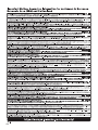
Contents
PRECAUTIONS ..................................................................... 4
Introduction ........................................................................... 6
Main Features........................................................................ 6
Structure of Manuals ............................................................. 6
Included Accessories............................................................ 6
Functions............................................................................... 7
HOME Screen...................................................................... 10
Main Menus and Examples of Screens............................... 11
Screen Operations .............................................................. 12
Using a USB Flash Drive to Save/Load Data ...................... 12
Basic Settings......................................................................13
Dante Connection................................................................14
Cardioid Mode Settings.......................................................15
Rotatable Horn.....................................................................16
Installation Examples...........................................................17
Optional Accessories (sold separately)...............................19
Troubleshooting ...................................................................19
General Specifications (English only)................................151
Dimensions (English only) .................................................153
Main Features
• Strong plywood cabinet features a high output Class D amplifier. Full-range models feature a powerful and lightweight neo-
dymium magnet.
• Optimized pairing of a highly durable speaker unit with a fixed directional horn, for sparkling highs with punchy and powerful
bass.
• Full-range models feature an FIR filter for crossover and frequency adjustments. Low latency for DSP and AD/DA, thanks to 96
kHz sampling rate.
• LCD screen for loading presets, and for making precise graphical adjustments to EQ, delay, and routings. Easily transfer set-
tings by using a USB flash drive.
• Dante models (-D) support the transmission of digital audio and remote control via a Dante network.
• 2-way models support use on a stand or use as a floor monitor. Rotation of the horn, several rigging points, and optional
brackets allow a variety of installation methods.
Structure of Manuals
• Owner’s Manual (this book): Mainly provides explana-
tions of the names, functions, and basic operations of each
component.
• Reference Manual: Mainly provides detailed explanations
of settings and operations. This can be downloaded from
the Yamaha Pro Audio global website.
http://www.yamahaproaudio.com/
Included Accessories
• Power cord
• Owner’s Manual (this book)
Type Standard Model Dante Model (-D)
Full Range
3-way 15" DZR315 DZR315-D
2-way 15" DZR15 DZR15-D
2-way 12" DZR12 DZR12-D
2-way 10" DZR10 DZR10-D
Subwoofer
18" DXS18XLF DXS18XLF-D
15" DXS15XLF DXS15XLF-D
Dante
Dante is a network audio transmission protocol developed by Audinate. It allows the transmission of uncompressed multi-channel digital
audio at low latency, as well as sample-level synchronization. Wiring is kept simple through connections using CAT5e cables.

7
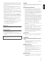
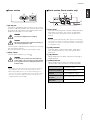
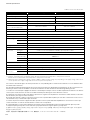
Full-range Speaker (Rear)
q Tiltable pole socket
This mount has two pole sockets. You can choose the
angle of the speaker so that it is positioned horizontal to
the floor or tilting down toward the floor by 7 degrees.
Compatible with commercially available speaker stands
and speaker poles of 35 mm diameter. (These sockets are
not available on the DZR315(-D).)
w Screw holes for U-bracket
For installing with the separately sold U-brackets. (These
sockets are not available on the DZR315(-D).)
e Screw holes for eye bolts
For installing the speaker using eye bolts. The screw holes
for eye bolts go through the cabinet wall.
Subwoofer (Rear)
r Dual pole sockets
Compatible with commercially available speaker poles of
35 mm diameter and M20 screw.
When using a pole socket to install a speaker, observe the
following conditions for safety.
t Feet cups
When stacking multiple speakers, align the rubber feet of
the upper speaker to the feet cups of the lower one.
y Wheel mounting screws
For installing the separately sold Yamaha SPW-1 wheels. If
you are not using wheels, do not remove these screws.
Otherwise, the leakage of air will affect sound quality.
w
q
e
Bottom
FRONT
7°
0°
7°
Pole socket
Subwoofer Speaker to be installed Length of the pole
DXS18XLF(-D)
Weight: 26 kg or less
Height: 76.0 cm or less
(DZR15(-D) or smaller)
104 cm or less
DXS15XLF(-D)
Weight: 22 kg or less
Height: 64.5 cm or less
(DZR12(-D) or smaller)
82 cm or less
Weight: 18 kg or less
Height: 53.7 cm or less
(DZR10(-D) or smaller)
104 cm or less
• For more information about installing wheels and related pre-
cautions, refer to the corresponding manual for the wheels.
• Do not install any item other than the SPW-1 wheels.
t
y
r
35 mm
diameter
M20 screw
NOTE
Functions
Full range
Subwoofer

8
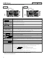
Functions
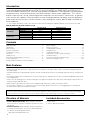
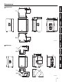
Rear Panel (for both Full-range Speakers and Subwoofers)
q USB terminal
For connecting a USB flash drive to save/load data.
w [LIMIT] indicator
Lights red when the limiter for protecting the speaker is
active. If the indicator remains on, lower the level of the
input signal.
e [POWER] indicator
Lights green when the power is on. Flashes green when
the protection function is active and the output is muted.
(“MUTED” appears on the HOME screen in the display at
this time.)
r Display
Shows the settings for various functions.
t Main knob
Turn the knob to move the cursor that appears in the dis-
play and change parameter values. Press the knob to
execute a setting.
y [ ] (Back) key
Press this key to move up the previous screen. Press and
hold the key to return to the HOME screen.
u [LEVEL] controls
Adjust the level that is input to the [INPUT] jacks.
i [INPUT] jacks
Combo jacks for line level input. Accept both XLR and
phone plugs.
o [THRU/OUTPUT] jacks
XLR output jacks. The output signal for channel 2 on full-
range speakers and both channels 1 and 2 on subwoof-
ers can be switched using the [THRU/DSP OUT] switch.
On full-range speakers, channel 1 is fixed to [THRU].
!0 [THRU/DSP OUT] switch
Selects whether to output the signals from the input jacks
without processing ([THRU]) or to output the signals after
DSP processing ([DSP OUT]).
!1 Vents
A cooling fan is installed on the exhaust side. When the
speaker is in use, take care that all of the vents are free
from obstruction.
NOTICE
When using a USB extension cable, use a cable that is no
longer than 1 m.
q
w
e
o
!0
!1
!1
y
r
i
t
u
Available only on Dante models
(See page 9.)
DZR(-D) Series DXS-XLF(-D) Series

9
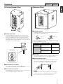
Functions
Power section
!2 [AC IN] jack
Connect the supplied AC power cord here. First, connect
the power cord to this product, then insert the power cord
plug into the AC outlet. When removing the power cord,
perform this procedure in reverse order.
Insert the power cord fully until it is locked by the latching
lock mechanism (V-Lock).
Press the V-Lock latch to disconnect the power cord.
!3 Power switch
Turns the power supply on [–] or off [ ].
Dante section (Dante models only)
!4 Dante jacks
These are etherCON jacks for a Dante network. Both jacks
are primary connections. They can be used for daisy
chain connections. For details, refer to the Reference
Manual.
!5 [LINK] indicator
Shows the Dante communication status. Lights green
when an Ethernet cable is connected correctly to the
Dante jack.
!6 [1G] indicator
Lights orange when the Dante network is functioning as
Gigabit Ethernet.
!7 [SYNC] indicator
Lights steady or flashes green according to the Dante
communication status, as shown in the following table.
WARNING
Use only the supplied power cord/plug.
CAUTION
Be sure to turn the power off before connecting or
disconnecting the power cord.
WARNING
A small amount of current flows even when the
power switch is off. If you will not use the speaker
for a long time, be sure to unplug the power cord
from the outlet.
• Depending on the timing when the power switch is turned on/
off, it might take up to 15 seconds for the power to turn on.
• When using multiple devices, we recommend turning each
device on one at a time. If multiple devices are turned on at the
same time, the devices might not start up correctly due to a
voltage drop at the power supply.
!3
!2
NOTE
Use STP (Shielded Twisted Pair) cables to prevent electromag-
netic interference. Make sure that the metal parts of the plugs are
electrically connected to the STP cable shield by conductive tape
or comparable means.
Steady
Operating normally as a clock slave
on the Dante network
Continuously flashing
Operating normally as a clock mas-
ter on the Dante network
Periodically flashing
one time
Incorrect DANTE FS setting
Periodically flashing
two times
Dante network cable not connected
Periodically flashing
three times
Incorrect Dante network connection
!7
!4
!5
!4
!5!6 !6
NOTE

10
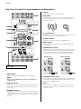
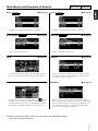
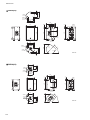
HOME Screen
The HOME screen appears when the power switch is turned on.
For details, refer to the Reference Manual on the Yamaha Pro Audio global website.
http://www.yamahaproaudio.com/
Display Description
q UNIT ID, LABEL
Shows the UNIT ID and label that are used for Dante. Allows you to go to the DANTE SETUP screen to
configure and display Dante settings.
w Input Meter
(“ANA” appears on DANTE
models.)
Shows the input level of the analog signal.
e Input Meter (DNT)
Shows the input level of the Dante signal.
r MASTER Level Displays and sets the output level (Unit: dB).
t SP Output Meter Shows the output level.
y Protection
(THERMAL, MUTED)
Appears when the protection function is active. “THERMAL” is shown when a high temperature is
detected in the amplifier (and the output level is reduced). If the conditions of the usage environment
become even worse, MUTED is displayed (and the output signal is muted).
u PRESET Shows the preset No. and title of the currently selected preset. Allows you to store, recall, and edit sound-
related settings. E symbol is displayed when you edit a parameter.
i HPF Allows you to configure and display the high-pass filter frequency settings.
LPF Allows you to configure and display the low-pass filter frequency and POLARITY settings. is displayed
when the polarity is set to INVERTED.
o D-CONTOUR
Allows you to configure and display the D-CONTOUR mode settings.
D-XSUB Allows you to configure and display the D-XSUB mode settings.
!0 EQ Shows if the equalizer is ON or OFF. Allows you to configure the EQ settings while checking the frequency
characteristics.
!1 DELAY Allows you to configure and display delay settings.
!2 CARDIOID Allows you to configure and display the cardioid mode settings.
!3 ROUTER Allows you to configure the routing of the audio signal.
!4 UTILITY Allows you to configure and display the following settings.
- PANEL SETUP: Configures display brightness, contrast, and display/indicator auto off settings.
- PANEL LOCK: Configures misoperation prevention setting, saves/loads PIN CODE.
- DEVICE BACKUP: Saves/loads configuration data.
- DANTE SETUP : Configures and displays Dante settings.
- NETWORK : Configures and displays network settings.
- DEVICE INFORMATION: Displays the status and information unique to this product.
- INITIALIZE: Performs initialization.
- LOG: Displays recorded logs. Saves logs to USB flash drive.
- UPDATE FIRMWARE: Update the firmware for the device, and the Dante module.
Full range
Subwoofer
o
i
!0
!1
w
e
!3
!4
q
uy
rt
o
!2
i
!0
!1
w
e
!3
!4
q
u
rt
y
Example (Dante models)
Full range
Example (Dante models)
Subwoofer
Dante model
Dante model
Full range
Subwoofer
Full range
Subwoofer
Subwoofer
Dante model
Dante model

11
HPF i on page 10
Configure the high-pass filter frequency settings.
D-CONTOUR o on page 10
Switch a D-CONTOUR preset.
EQ !0 on page 10
Configure the equalizer settings. The total gain character-
istics for a 6-band equalizer are displayed on a graph.
ROUTER !3 on page 10
Configure the routing of the audio signal. Set for the
routing point of the signal you want to output. You can set
the input and output levels by selecting INPUT or OUTPUT
and going to the INPUT or OUTPUT level setting screen.
LPF i on page 10
Configure the low-pass filter frequency settings.
D-XSUB o on page 10
Switch a low range characteristic.
DELAY !1 on page 10
Allows you to switch the delay ON or OFF, and configure
three types of delay settings. Editing one type will affect
the settings for the other types.
PRESET u on page 10
Allows you to store up to eight sound-related settings.
When using the DZR and DXS-XLF series, simply recalling
the preset of the speaker model to be used optimizes the
corresponding settings. Recalling INITIAL DATA allows
you to return to the factory settings.
For details, refer to the Reference Manual on the Yamaha Pro Audio global website.
http://www.yamahaproaudio.com/
Full range
Full range
Subwoofer
Subwoofer
Main Menus and Examples of Screens
Full range
Subwoofer

12
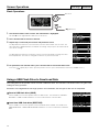
Screen Operations
Basic Operations
1. Turn the main knob to select an item. The selected item is highlighted.
An arrow > on the right indicates that there is sub menu.
2. Press the main knob to execute a selection.
3. Repeat steps 1 and 2 until you reach the edit parameter screen.
To edit parameters that have selected values, turn the main knob to select a value. The
value will not be updated and the sound will not change until you press the main knob to
execute the change.
To edit parameters that have continuous values, turn the main knob to change the value
for that parameter. The value is changed in real time as you turn the knob.
4. For parameters with selected values, press the main knob to execute the edited value.
Press the [ ] (back) key to move up to the previous screen. (Press and hold it to return to the HOME screen.)
Using a USB Flash Drive to Save/Load Data
The setting data for this product can be saved to a USB flash drive. This function is convenient when using the same
settings for many speakers.
Saved files are categorized into full-range speakers and subw oofers; the two types of files are not compatible.
Save to USB flash drive (SAVE)
On the HOME screen of the speaker that is the data source, select UTILITY DEVICE
BACKUP SAVE TO USB. Follow the on-screen instructions to save the data.
Load from USB flash drive (RESTORE)
On the HOME screen of the speaker to which the data will be loaded, select UTILITY
DEVICE BACKUP RESTORE FROM USB. Follow the on-screen instructions to load the
data.
Full range
Subwoofer
Main knob
[ ] (Back) key

13
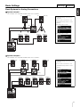
Basic Settings
Basic Systems for Analog Connections
System example 1
This example uses only DZR and DXS-XLF series speakers.
System example 2
This example uses only DZR and DXS-XLF series speakers.
Full range
Subwoofer
Analog Mixer
A FOH (L) A FOH (R)
(L+R)
[THRU]
B
MONI1-1 MONI1-2
[THRU]
MONI2-1 MONI2-2
[THRU]
• Individual analog connections on
each bus
• For the same sound source, use
[THRU/DSP OUT] switch to set to
[THRU]
• Recalling a preset at A
• Recalling a preset at B
Analog Mixer
D
(L)
C FOH
(L)
C FOH
(R)
Side
(R)
Side
(L)
D
(R)
[THRU] [THRU]
MONI1 MONI2 MONI3 MONI4-1 MONI4-2
[THRU]
• Individual analog connections on
each bus
• For the same sound source, use
[THRU/DSP OUT] switch to set to
[THRU]
• Recalling a preset at C
• Recalling a preset at D

14
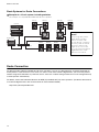
Dante Connection
Basic Systems for Dante Connections
Example of a 15-unit system, including switches
This example uses only DZR-D and DXS-XLF-D series speakers.
Dante Connection
For Dante models (DZR-D and DXS-XLF-D series speakers), you can use Dante devices and Dante Controller to
make patches. If you connect to a TF series, CL series, or QL series Yamaha digital mixer, you can make patches
without using Dante Controller. In particular, the TF series has a Quick Config function that can be configured easily
to make patches automatically.
For details, refer to the Reference Manuals for DZR(-D) and DXS-XLF(-D) series speakers. (For details about how to
use Yamaha digital mixers, refer to the manual for each individual model.)
http://www.yamahaproaudio.com/
(L)
MONI1 MONI2 MONI3 MONI4
Configuration with Dante
Models
Keep a single daisy chain to
within 10 units, including
switches. If a daisy chain
exceeds 10 units, communica-
tion latency within the network
will increase and the audio
might cut out. In such cases,
use an L2 switch (that supports
Gigabit Ethernet) to create
branches in the network.
I/O rack
Side (L) FOH (L) FOH (R) Side (R)
(R)
L2 switch
Digital mixer

15
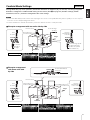
Cardioid Mode Settings
Arrange DXS-XLF(-D) series speakers (hereinafter referred to as DXS-XLF(-D)) so that they are facing in opposite
directions. Configure the cardioid mode setting on the screen. (See !2 on page 10.) All other settings (LEVEL,
POLARITY, LPF etc.) should be configured to the same settings.
Example arrangement with two units side by side
• Use the same DXS-XLF(-D) model, and the same input signal. You can also set the [THRU/DSP OUT] switch to [THRU] to use in a sequence
connection. See the example arrangements below.
• In order to maximize the cardioid characteristics, position the cabinets at least 1.2 m away from walls.
Subwoofer
NOTE
From the mixer
To the full-range
speakers
From
the mixer
To the DXS-
XLF(-D) on
the right
Audience
Stage
CARDIOID settings
From the
DXS-XLF(-D)
on the left
To the full-range speak-
ers (when full-range
speakers are placed
after subwoofers)
Example arrangement
with three units side
by side
CARDIOID settings
Audience
Stage
From the mixer
To the DXS-XLF(-D)
on the right
From the DXS-XLF(-D)
on the left
From the
DXS-XLF(-D)
in the center
From
the mixer
To the DXS-
XLF(-D) in
the center

16
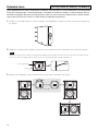
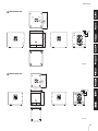
Rotatable Horn
When shipped from the factory, the directivity of DZR(-D) series speaker in a vertical orientation is the setting which
makes the sound expand in a horizontal direction, and inhibits or narrows the sound in a vertical direction. We rec-
ommend changing the directivity by rotating the horn when you want to install the DZR(-D) series speaker horizon-
tally or when you want to use them as a floor monitor and broaden the directivity.
1. Using a 2.5 mm hexagonal wrench, remove all fixing screws (DZR10(-D): six total) on the grille, and remove the grille from
the speaker.
2. Using a No. 2 Phillips head screwdriver, remove all screws installed on the horn and pull the horn out from the speaker.
3. Rotate the horn 90 degrees, and re-install the horn to the speaker, reversing the steps above.
• Make sure not to push the screws too strongly with the Phillips head screwdriver. This may cause the nuts inside the cabinet to fall off.
• If the horn cannot smoothly be pulled out, hook the notches using a flat-bladed screwdriver, and pull out.
Full range: DZR15(-D), DZR12(-D), and DZR10(-D)
NOTE
Screws (eight total)
Notch
Vertical
Rotate 90°
Horizontal

17
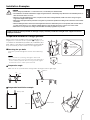
Installation Examples
Suspended Installation Using Eye Bolts
Suspension angle
Make sure to use eye bolts within a range of 0 to 45 degrees from a right angle.
Suspended installation example
CAUTION
• Before doing any installation or construction work, consult with your Yamaha dealer.
• The installation should be checked thoroughly at regular intervals. Some fittings may deteriorate over extended periods of
time due to wear and/or corrosion.
• When choosing the installation location, suspension wire and mounting hardware, make sure all are strong enough to
support the weight of the speaker.
• Make sure to take precautionary measures using wires to prevent the speaker from falling down in the event of an installa-
tion failure.
• When installing the wire to the wall, install it higher than the wire’s attachment point on the speaker, with as little slack as
possible. If the wire is too long, and the speaker happens to fall, the wire may snap as a result of too much strain.
• Make sure to use eye bolts according to the standards and safety regulations in your area.
Yamaha cannot be held responsible for damage or injury caused by insufficient strength of the support structure or
improper installation.
Full range
Attach commercially available long eye bolts (30–50 mm in
length) to the screw holes for the eye bolts (e on page 7). The
screw diameter for DZR315(-D), DZR15(-D), and DZR12(-D) is
M10, and the screw diameters for DZR10(-D) are M10 and M8.
Keep in mind that you will need two or more rigging points.
Securing the eye bolts
Insert the eye bolts through the washers when attaching
them.
• The screw holes for eye bolts go through the cabinet wall.
• When using eye bolts, remove the flat-head screws tightened at
the time of factory shipment. When not using eye bolts, tighten
the flat-head screws in order to prevent air leaks.
NOTE
Apply thread-
locking fluid
to the eye bolt
Bottom
0°
45°
Max. 45°
M10 eye bolt
Pullback point
Side
Rear
Max. 45°

18
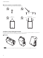
Installation Examples
Incorrect examples for suspended installation
Do not suspend the eye bolts as shown in the illustrations below.
Installation Using a Dedicated U-bracket
By using the separately sold Yamaha UB-DZR series U-bracket, you can expand the installation possibilities. For instructions on
installing the U-bracket, refer to the corresponding manual for the UB-DZR series.
Examples
The UB-DZR series can be used together with separately sold optional brackets, such as the Yamaha BBS251 Baton Bracket.
Prohibited Prohibited
Prohibited Prohibited
More than 45° from
a right angle
More than
45°
More than
45°
Only one
suspension point
NOTE

19
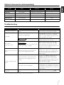
Optional Accessories (sold separately)
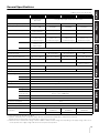
Troubleshooting
If any specific problem should persist, please contact your Yamaha dealer.
Speaker Cover U-bracket Wheels
DZR315(-D) SPCVR-DZR315 — —
DZR15(-D) SPCVR-DZR15 UB-DZR15H, UB-DZR15V —
DZR12(-D) SPCVR-DZR12 UB-DZR12H, UB-DZR12V —
DZR10(-D) SPCVR-DZR10 UB-DZR10H, UB-DZR10V —
DXS18XLF(-D) SPCVR-DXS18X — SPW-1
DXS15XLF(-D) SPCVR-DXS15X — SPW-1
Symptom Possible causes Possible solution
Power does not come on.
Time between turning the power on/off is too
short.
Wait about 20 seconds after turning the
power off before turning it back on again.
No sound.
Routing is not appropriate.
On the HOME screen, if there is a signal in the
Input Meter but no signal in the SP Output
Meter, check if the signal is routed to SP OUT
under ROUTER in the settings.
Level is low in DSP.
Check the INPUT level under ROUTER in the
settings, and raise it if it is too low.
No sound, or
intermittent sound.
Too many Dante devices in the daisy chain
for the current latency settings.
With the default setting (1 msec), a single
daisy chain can have up to 10 units. When
connecting more than 10 units, use an L2
switch (that supports Gigabit Ethernet) to cre-
ate branches in the network.
Volume becomes low sud-
denly.
Protection function is active because the
amp is too hot, triggering the limiter.
In such cases, THERMAL is displayed on the
HOME screen. To prevent the speaker from
getting hotter, improve the ventilation around
the rear panel and shield the panel from
direct sunlight.
Sound is interrupted sud-
denly.
Protection function is active because the
amp became hotter, triggering the mute
function.
In such cases, MUTED is displayed on the
HOME screen and at the same time the
[POWER] indicator flashes. To prevent the
speaker from getting hotter, improve the venti-
lation around the rear panel and shield the
panel from direct sunlight.
The speaker units are damaged.
If there is no sound even though MUTED is
not displayed on the HOME screen and there
is a signal in the SP Output Meter, the speaker
units might be damaged. Please contact your
Yamaha dealer.
Display goes off after a few
moments.
The protection function for the display is
active.
Press either the main knob or the [ ]
(back) key to return to the normal display.
Dante model
Dante model

151
General Specifications
0 dBu is referenced to 0.775 Vrms.
*1: Measured peak SPL with pink noise @1 m.
*2: Dynamic: Total peak power of individual outputs. Measured at minimum load impedance, with protection released.
Burst/Continuous: Measured at nominal impedance, with protection activated.
*3: While both devices will work at a voltage of between 100 V to 240 V, as limiter settings vary depending on the supply voltage, make sure to
use this product at the supply voltage indicated on the rear panel of this product.
DZR315(-D) DZR15(-D) DZR12(-D) DZR10(-D)
System Type 3-way, Bi-amped
powered speaker,
Bass-reflex
2-way, Bi-amped powered speaker, Bass-reflex
Frequency Range (-10 dB) 31 Hz – 20 kHz 34 Hz – 20 kHz 39 Hz – 20 kHz 44 Hz – 20 kHz
Coverage Angle
H75° × V50°
H90° × V50°
(Rotatable)
H90° × V60°
(Rotatable)
H90° × V60°
(Rotatable)
Crossover Frequency, Type 700 Hz (FIR-X)
2.5 kHz (Passive)
1.7 kHz (FIR-X) 1.8 kHz (FIR-X) 1.8 kHz (FIR-X)
Maximum SPL
*1
143 dB SPL 139 dB SPL 139 dB SPL 137 dB SPL
Transducer LF 15" Cone,
3" Voice coil,
Neodymium magnet
15" Cone,
3" Voice coil,
Neodymium magnet
12" Cone,
3" Voice coil,
Neodymium magnet
10" Cone,
3" Voice coil,
Neodymium magnet
MF 8" Cone,
1.5" Voice coil,
Ferrite magnet
—
HF 2" Voice coil, 1" Throat compression driver, Titanium diaphragm, Neodymium magnet
Enclosure Material, Finish, Color Plywood, Durable polyurea coating, Black
Floor Monitor Angle — 50° Symmetrical 50° Symmetrical 50°
Dimensions
(W × H × D, with rubber feet)
550 × 897 × 520 mm 450 × 761 × 460 mm 410 × 646 × 394 mm 315 × 537 × 345 mm
Weight 41.6 kg 25.2 kg 21.4 kg 17.9 kg
Handles
Aluminium die-cast, Side × 2
Aluminium die-cast,
Top × 1, Side × 1
Pole Socket — Ø35 mm × 2 (0° or -7°)
Rigging Points M10 × 16 M10 × 12 M10 × 8, M8 × 2
Amplifier Type Class-D
Power Rating
*2
Dynamic 2000 W (LF:1000 W, MF/HF: 1000 W)
Burst (20ms) 1100 W (LF: 1000 W, MF/HF: 100 W)
Continuous 950 W (LF: 850 W, MF/HF: 100 W)
Cooling Fan cooling, Variable speeds.
DSP, AD/DA 96 kHz processing with 96 kHz AD/DA and FIR filter
Connectors Analog IN Combo × 2, Line level (Maximum +24 dBu), Input impedance: 20 kΩ
Analog OUT XLR3-32 × 2, CH1: THRU (fix), CH2: THRU or DSP OUT
Dante
(-D model only)
etherCON CAT5e × 2 (Daisy chain), 2 IN / 2 OUT (Fs: 44.1k, 48k, 88.2k, 96k) and
Remote control, 1000BASE-T
USB USB 2.0 host: 5 V 500 mA
AC IN IEC AC inlet × 1 (V-Lock)
Idle Power Consumption 45 W
1/8 Power Consumption 150 W
AC Power Requirements
*3
Depending on area of purchase; 100–240 V or 220–240 V, 50/60 Hz
Optional
Accessories
U-bracket
—
UB-DZR15H,
UB-DZR15V
UB-DZR12H,
UB-DZR12V
UB-DZR10H,
UB-DZR10V
Cover SPCVR-DZR315 SPCVR-DZR15 SPCVR-DZR12 SPCVR-DZR10
General Specifications (English only)
Seite laden ...
Seite laden ...
Seite laden ...
Seite laden ...
Seite laden ...
Seite laden ...
Seite laden ...
Seite laden ...
Seite laden ...
Seite laden ...
Seite laden ...
-
 1
1
-
 2
2
-
 3
3
-
 4
4
-
 5
5
-
 6
6
-
 7
7
-
 8
8
-
 9
9
-
 10
10
-
 11
11
-
 12
12
-
 13
13
-
 14
14
-
 15
15
-
 16
16
-
 17
17
-
 18
18
-
 19
19
-
 20
20
-
 21
21
-
 22
22
-
 23
23
-
 24
24
-
 25
25
-
 26
26
-
 27
27
-
 28
28
-
 29
29
-
 30
30
-
 31
31


Yamaha DXS15XLF Bedienungsanleitung
- Kategorie
- Audio-Equalizer
- Typ
- Bedienungsanleitung
in anderen Sprachen
- English: Yamaha DXS15XLF Owner's manual
- français: Yamaha DXS15XLF Le manuel du propriétaire
- español: Yamaha DXS15XLF El manual del propietario
- italiano: Yamaha DXS15XLF Manuale del proprietario
- русский: Yamaha DXS15XLF Инструкция по применению
- Nederlands: Yamaha DXS15XLF de handleiding
- português: Yamaha DXS15XLF Manual do proprietário
- dansk: Yamaha DXS15XLF Brugervejledning
- polski: Yamaha DXS15XLF Instrukcja obsługi
- čeština: Yamaha DXS15XLF Návod k obsluze
- svenska: Yamaha DXS15XLF Bruksanvisning
- Türkçe: Yamaha DXS15XLF El kitabı
- română: Yamaha DXS15XLF Manualul proprietarului
Verwandte Papiere
-
Yamaha DZR10 Benutzerhandbuch
-
Yamaha DXR8 MKII Benutzerhandbuch
-
Yamaha MSP3A Powered Speaker System Bedienungsanleitung
-
-
Yamaha DXS18 Bedienungsanleitung
-
Yamaha DSR-100PRO Bedienungsanleitung
-
Yamaha MS45DR Bedienungsanleitung
-
-
Yamaha DBR15 Benutzerhandbuch
-