
Operating instructions
Betriebsanleitung
Mode d'emploi
Manual de instrucciones
EN
DE
FR
ES
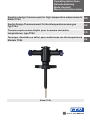
Sapphire-design thermocouple for high-temperature measurements
Model TC84
Saphir-Design-Thermoelement für Hochtemperaturmessungen
Typ TC84
Thermocouple version Saphir pour la mesure de hautes
températures, type TC84
Termopar diseñado en zafiro para mediciones de alta temperatura
Modelo TC84
Model TC84

EN
DE
FR
ES
2
14274725.02 08/2018 EN/DE/FR/ES
WIKA operating instructions model TC84
Operating instructions model TC84
Page
3 - 20
Betriebsanleitung Typ TC84
Seite
21 - 38
Mode d‘emploi type TC84
Page
39 - 56
Manual de instrucciones modelo TC84
Página
57 - 73
© 07/2018 WIKA Alexander Wiegand SE & Co. KG
All rights reserved. / Alle Rechte vorbehalten.
WIKA
®
is a registered trademark in various countries.
WIKA
®
ist eine geschützte Marke in verschiedenen Ländern.
Prior to starting any work, read the operating instructions!
Keep for later use!
Vor Beginn aller Arbeiten Betriebsanleitung lesen!
Zum späteren Gebrauch aufbewahren!
Lire le mode d‘emploi avant de commencer toute opération !
A conserver pour une utilisation ultérieure !
¡Leer el manual de instrucciones antes de comenzar cualquier trabajo!
¡Guardar el manual para una eventual consulta!

EN
Contents
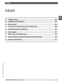
Contents
14274725.02 08/2018 EN/DE/FR/ES
WIKA operating instructions model TC84 3
1. General information 4
2. Design and function 5
3. Safety 7
4. Transport, packaging and storage 10
5. Commissioning, operation 11
6. Faults 14
7. Maintenance and cleaning 16
8. Dismounting, return and disposal 17
9. Specifications 19

EN
1. General information
14274725.02 08/2018 EN/DE/FR/ES
WIKA operating instructions model TC844
1. General information
■
The instrument described in the operating instructions has been manufactured
using state-of-the-art technology. All components are subject to stringent quality and
environmental criteria during production. Our management systems are certified to
ISO 9001 and ISO 14001.
■
These operating instructions contain important information on handling the instrument.
Working safely requires that all safety instructions and work instructions are observed.
■
The operating instructions are part of the product and must be kept in the immediate
vicinity of the instrument and readily accessible to skilled personnel at any time. Pass
the operating instructions on to the next operator or owner of the instrument.
■
Observe the relevant local accident-prevention regulations and general safety
regulations for the instrument's range of use.
■
Skilled personnel must have carefully read and understood the operating instructions
prior to beginning any work.
■
The general terms and conditions contained in the sales documentation shall apply.
■
Subject to technical modifications.
■
Further information:
- Internet address: www.wika.de / www.wika.com
- Application consultant:
Tel.: +49 9372 132-0
Fax: +49 9372 132-406
info@wika.de

EN
2. Design and function
14274725.02 08/2018 EN/DE/FR/ES
WIKA operating instructions model TC84 5
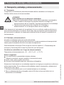
2. Design and function
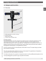
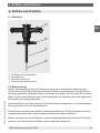
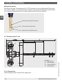
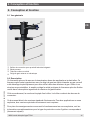
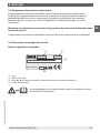
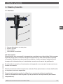
2.1 Overview
Solid-machined connection housing
Process flange
Metal support tube
Ceramic outer protection tube
2.2 Description
This thermocouple is used for temperature measurement in industrial applications. This
high-temperature thermocouple with a gas-tight sapphire protection tube has been
specifically developed for use in gas reactors. Through the monocrystalline structure, the
sapphire protects the precious metal of the thermocouple from poisonous toxic media in
the aggressive atmosphere of the gasification reactor.
For the connection side, the thermometer is fitted with a case. The case design contains
the connection terminals.
This document describes standard versions of instruments. For applications in hazardous
areas special instrument designs are required.
For further information for operation in hazardous areas, see the additional information for the
corresponding ignition protection type (separate document).

EN
2. Design and function
14274725.02 08/2018 EN/DE/FR/ES
WIKA operating instructions model TC846
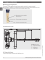
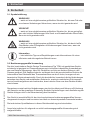
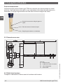
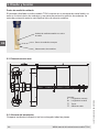
Measuring point ungrounded
The model TC84 sapphire-design thermocouple consists of a precious metal
thermocouple, a sapphire or ceramic inner tube and a ceramic external protection tube.
This external protection tube is fixed into the metal support tube.
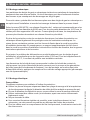
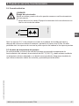
2.3 Dimensions in mm
2.4 Scope of delivery
Cross-check scope of delivery with delivery note.
Thermocouple measuring point
Ceramic outer protection tube
Measuring insert with sapphire
protection tube
Legend:
U Insertion length
SL Support tube length
Sealing cap
Cable outlet

EN
3. Safety
14274725.02 08/2018 EN/DE/FR/ES
WIKA operating instructions model TC84 7
3. Safety
3.1 Explanation of symbols
WARNING!
... indicates a potentially dangerous situation that can result in serious injury
or death, if not avoided.
CAUTION!
... indicates a potentially dangerous situation that can result in light injuries or
damage to property or the environment, if not avoided.
WARNING!
... indicates a potentially dangerous situation that can result in burns, caused
by hot surfaces or liquids, if not avoided.
Information
... points out useful tips, recommendations and information for efficient and
trouble-free operation.
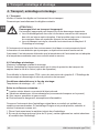
3.2 Intended use
The model TC84 sapphire-design thermocouple, with gas-tight sapphire protection tube,
described here is suitable for temperature measurement in critical industrial applications
such as gasification or GtL reactors and is suitable for direct installation into the process.
Due to its monocrystalline structure, the sapphire protection tube extends the life of the
thermocouple's precious metal by 3 times, in comparison to purely ceramic protection
tube materials. As a result of the pressure-tight, hermetically sealed junctions between the
sapphire and metal protection tube, and also a multifold sealing system in the connection
housing, toxic gases are prevented from being able to escape from the reactor.
Neither repairs nor structural modifications are permitted, and any would void the
guarantee and the respective certification. The manufacturer shall not be responsible for
constructional modifications after delivery of the instruments.
The instrument has been designed and built solely for the intended use described here,
and may only be used accordingly.
The technical specifications contained in these operating instructions must be observed.
The manufacturer shall not be liable for claims of any type based on operation contrary to
the intended use.

EN
3. Safety
14274725.02 08/2018 EN/DE/FR/ES
WIKA operating instructions model TC848
3.3 Responsibility of the operator
The system operator is responsible for selecting the thermometer or protection tube, and
for the selection of their materials, so as to guarantee their safe operation within the plant
or machine. When preparing a quote, WIKA can only give recommendations which are
based on our experience in similar applications.
The safety instructions within these operating instructions, as well as the safety, accident
prevention and environmental protection regulations for the application area must be
maintained.
The operator is obliged to maintain the product label in a legible condition.
3.4 Personnel qualification
WARNING!
Risk of injury should qualification be insufficient
Improper handling can result in considerable injury and damage to
equipment.
▶
The activities described in these operating instructions may only be
carried out by skilled electrical personnel who have the qualifications
described below.
Skilled electrical personnel
Skilled electrical personnel are understood to be personnel who, based on their technical
training, know-how and experience as well as their knowledge of country-specific
regulations, current standards and directives, are capable of carrying out work on
electrical systems and independently recognising and avoiding potential hazards. The
skilled electrical personnel have been specifically trained for the work environment they
are working in and know the relevant standards and regulations. The skilled electrical
personnel must comply with current legal accident prevention regulations.
Operating personnel
The personnel trained by the operator are understood to be personnel who, based on their
education, knowledge and experience, are capable of carrying out the work described and
independently recognising potential hazards.
Special operating conditions require further appropriate knowledge, e.g. of aggressive
media.

EN
3. Safety
14274725.02 08/2018 EN/DE/FR/ES
WIKA operating instructions model TC84 9
3.5 Personal protective equipment
The personal protective equipment is designed to protect the skilled personnel from
hazards that could impair their safety or health during work. When carrying out the various
tasks on and with the instrument, the skilled personnel must wear personal protective
equipment (e.g. gas detector, harness, etc.).
Follow the instructions displayed in the work area regarding personal protective
equipment!
The requisite personal protective equipment must be provided by the operating company.
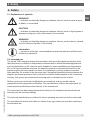
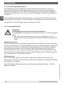
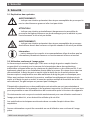
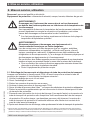
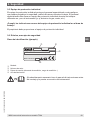
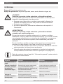
3.6 Labelling, safety marks
Product label (example)
Model
Serial number
Information on version (measuring element, measuring range...)
Year of manufacture
Before mounting and commissioning the instrument, ensure you
read the operating instructions!
TC84
1 x Type K / 1 / .
0 ... 1260 °C
IEC 60584
Made in Germany
2015
11012345
D-63911 Klingenberg

EN
4. Transport, packaging and storage
14274725.02 08/2018 EN/DE/FR/ES
WIKA operating instructions model TC8410
4. Transport, packaging and storage
4.1 Transport
Check the instrument for any damage that may have been caused by transport.
Obvious damage must be reported immediately.
CAUTION!
Damage through improper transport
With improper transport, a high level of damage to property can occur.
▶
When unloading packed goods upon delivery as well as during internal
transport, proceed carefully and observe the symbols on the packaging.
▶
With internal transport, observe the instructions in chapter 4.2 “Packaging
and storage”.
If the instrument is transported from a cold into a warm environment, the formation of
condensation may result in instrument malfunction. Before putting it back into operation,
wait for the instrument temperature and the room temperature to equalise.
4.2 Packaging and storage
Do not remove packaging until just before mounting.
Store the Styrofoam packaging as well as the protective transport tube of the probe for any
return transport (repair option).
To unpack the TC84 thermocouple, follow chapter 5.1 “Unpacking the thermocouple and
dismounting the protective transport tube”.
Permissible conditions at the place of storage:
Storage temperature: -40 ... +80 °C [-40 ... +176 °F]
Avoid exposure to the following factors:
■
Direct sunlight or proximity to hot objects
■
Mechanical vibration, mechanical shock (putting it down hard)
■
Soot, vapour, dust and corrosive gases
■
Hazardous environments, flammable atmospheres
Store the instrument in its original packaging in a location that fulfils the conditions listed
above. If the original packaging is not available, pack and store the instrument as described
below:
1. Place the instrument, along with shock-absorbent material, in the packaging.
2. If stored for a prolonged period of time (more than 30 days), place a bag containing a
desiccant inside the packaging.

EN
5. Commissioning, operation
14274725.02 08/2018 EN/DE/FR/ES
WIKA operating instructions model TC84 11
5. Commissioning, operation
Personnel: Skilled electrical personnel
Protective equipment: Safety clothing, helmet, harness, gas detector etc.
WARNING!
Damage to the measuring instrument by operation outside the upper or
lower limits of the operating temperature
Failure to observe the permissible operating temperature, also taking into
account convection and radiation, can even cause damage to the thermometer
during mounting.
▶
The upper and lower limits of the specified operating temperature range
must not be exceeded.
WARNING!
Physical injuries and damage to property and the environment caused
by hazardous media
Upon contact with hazardous media (e.g. oxygen, acetylene, flammable
or toxic substances), harmful media (e.g. corrosive, toxic, carcinogenic,
radioactive), and also with refrigeration plants and compressors, there is a
danger of physical injuries and damage to property and the environment.
Should a failure occur, aggressive media with extremely high temperature
and under high pressure or vacuum may be present at the instrument.
▶
For these media, in addition to all standard regulations, the appropriate
existing codes or regulations must also be followed.
▶
Wear the requisite protective equipment.
5.1 Unpacking the thermocouple and dismounting the protective transport tube
When unpacking the TC84 thermocouple, and also when removing the protective transport
tube, carry out the following steps:
1. Check the packaging for damage.
2. Open cardboard packaging.
3. Remove foam padding.
4. Lift out the TC84 thermocouple with two people.
5. Clamp the process flange in the vice
1)
using suitable protective jaws.
6. Remove the additional protection from between the ceramic tube and the protective
transport tube.
7. Carefully and alternately loosen the three clamping screws on the protective transport
tube in order to prevent any tilting of the protective transport tube. At the same time, a
second person must observe the opening of the protective transport tube at the lower
end in order to prevent any contact of the tube wall with the ceramic.
8. After loosening the clamping screws, carefully pull the protective transport tube off.
1) If no vice is available, we recommend disassembling on a workbench. The first person must support the connection
head and at the same time loosen the threaded connection as described in point 7. The second person, in the meantime,
supports the protective transport tube and pulls it off carefully.

EN
5. Commissioning, operation
14274725.02 08/2018 EN/DE/FR/ES
WIKA operating instructions model TC8412
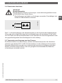
5.2 Mechanical mounting
Ceramic protection tube materials withstand changes in temperature only to a limited
extent. A temperature shock can therefore easily result in stress cracks and consequently
in damage to the protection tube.
For this reason, preheat thermocouples with ceramic or sapphire protection tubes before
installation, and then slowly immerse them into the hot process.
In accordance with DIN 43724, an insertion speed of 1 cm/min is recommended for
protection tubes with a diameter of 24/26 mm. For smaller diameters of 10/15 mm, the
speed can be increased to 50 cm/min. As a basic principle, higher process temperatures
require a lower insertion speed.
In addition to the protection from thermal stress, ceramic protection tubes must also be
protected from mechanical loads. The reason for these harmful stresses are bending forces
in case of a horizontal mounting position. As a consequence, an additional support must
be provided in case of a horizontal mounting position depending on the diameter, greater
nominal lengths and the design.
In principle, the deflection problem also occurs for metal protection tubes, particularly for
insertion lengths > 500 mm. For process temperatures > 1,200 °C [> 2,192 °F], vertical
mounting should be preferred.
The flange dimensions must match those of the mating flange on the process side. The
seals used must be suitable for the process and the flange geometries (consult the delivery
note). When mounting, depending on the seals used, use the appropriate tightening
torques and tools (e.g. torque spanner).
5.3 Electrical mounting
Cable glands
Requirements for meeting ingress protection:
■
Only use cable glands within their indicated clamping range and operating temperature
(cable diameter suitable for the cable gland).
■
Do not use the lower clamping area with very soft cable types.
■
Only use round cables (if necessary, slightly oval in cross-section).
■
Do not twist the cable.
■
Repeated opening/closing is possible; however only if necessary, as it might have a
detrimental effect on the ingress protection
■
For cables with a pronounced cold-flow behaviour the screw connection must be fully
tightened.

EN
5. Commissioning, operation
14274725.02 08/2018 EN/DE/FR/ES
WIKA operating instructions model TC84 13
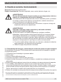
5.4 Electrical connection
CAUTION!
Danger of short circuit
Damage to cables, wires and connection points can lead to malfunction of
the instrument.
▶
Avoid damaging the cables and wires. Fine-stranded leads with bare ends
must be finished with end splices.
Open the G 1 ¼ sealing caps of the connection head on the head side of the cable entry
and after fitting the connection leads, tighten to at least 50 Nm. Opening the plug screws
on the top of the connection housing and the sealing caps opposite is not permitted.
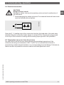
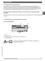
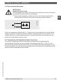
5.5 Temperature carry-over from the process
Any heat reflux from the process which exceeds the operating temperature of the
connection housing of a maximum of 200 °C [392 °F], is not permitted and must be
prevented by suitable thermal insulation or a corresponding structural design. Furthermore,
make sure that only suitable connection cables and cable glands are used.
14274948.01

EN
6. Faults
14274725.02 08/2018 EN/DE/FR/ES
WIKA operating instructions model TC8414
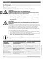
6. Faults
Personnel: Skilled electrical personnel
Protective equipment: Safety clothing, helmet, harness, gas detector etc.
CAUTION!
Physical injuries and damage to property and the environment
If faults cannot be eliminated by means of the listed measures, the instrument
must be taken out of operation immediately.
▶
Ensure that there is no longer any signal present and protect against being
put into operation accidentally.
▶
Contact the manufacturer.
▶
If a return is needed, please follow the instructions given in chapter 8.2
“Return”.
WARNING!
Physical injuries and damage to property and the environment caused
by hazardous media
Upon contact with hazardous media (e.g. oxygen, acetylene, flammable
or toxic substances), harmful media (e.g. corrosive, toxic, carcinogenic,
radioactive), and also with refrigeration plants and compressors, there is a
danger of physical injuries and damage to property and the environment.
Should a failure occur, aggressive media with extremely high temperature
and under high pressure or vacuum may be present at the instrument.
▶
For these media, in addition to all standard regulations, the appropriate
existing codes or regulations must also be followed.
▶
Wear the required protective equipment (depending on the application; the
thermometer itself is basically not dangerous).
For contact details see chapter 1 “General information” or the back page of
the operating instructions.
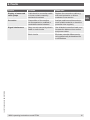
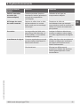
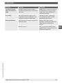
Faults Causes Measures
No signal/cable break Mechanical load too high or
damage
Replace the thermometer
Erroneous measured
values and response
times too long
Wrong mounting geometry, for
example mounting depth too
deep or heat dissipation too high
The temperature-sensitive area
of the sensor must be within the
medium
Deposits on the sensor or
protection tube
Remove deposits
Erroneous
measured values (of
thermocouples)
Parasitic voltages (thermal
voltages, galvanic voltage) or
wrong compensating cable
Use suitable compensating cable

EN
6. Faults
14274725.02 08/2018 EN/DE/FR/ES
WIKA operating instructions model TC84 15
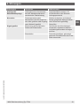
Faults Causes Measures
Display of measured
value jumps
Cable break in connection cable
or loose contact caused by
mechanical overload
Replace the connection cable e.g.
with bend protection or thicker
conductor cross-section
Corrosion Composition of the medium
not as expected or modified or
unsuitable material selected
Analyse medium and then select a
more-suitable material or check the
protection tube regularly
Signal interference Stray currents caused by electric
fields or earth circuits
Use shielded connection leads, and
increase the distance from motors
and power cables
Earth circuits Eliminate potential differences by
using galvanically isolated barriers
or transmitters

EN
7. Maintenance and cleaning
14274725.02 08/2018 EN/DE/FR/ES
WIKA operating instructions model TC8416
7. Maintenance and cleaning
For contact details see chapter 1 “General information” or the back page of
the operating instructions.
7.1 Maintenance
The thermometers described here are maintenance-free.
Repairs must only be carried out by the manufacturer.
7.2 Cleaning
CAUTION!
Physical injuries and damage to property and the environment
Improper cleaning may lead to physical injuries and damage to property and
the environment. Residual media in the dismounted instrument can result in a
risk to persons, the environment and equipment.
▶
Carry out the cleaning process as described below.
1. Prior to cleaning, properly disconnect the instrument.
2. Use the required protective equipment (depending on the application; the thermometer
itself is basically not dangerous).
3. Clean the instrument with a moist cloth.
This applies in particular to thermometers with a case made of plastic and cable probes
with plastic-insulated connection lead, to ensure that any risk of electrostatic charge is
avoided.
Electrical connections must not come into contact with moisture!
CAUTION!
Damage to the instrument
Improper cleaning may lead to damage to the instrument!
▶
Do not use any aggressive cleaning agents.
▶
Do not use any hard or pointed objects for cleaning.
4. Wash or clean the dismounted instrument, in order to protect persons and the
environment from exposure to residual media.

EN
8. Dismounting, return and disposal
14274725.02 08/2018 EN/DE/FR/ES
WIKA operating instructions model TC84 17
8. Dismounting, return and disposal
8.1 Dismounting
WARNING!
Physical injuries and damage to property and the environment
through residual media
Upon contact with hazardous media (e.g. oxygen, acetylene, flammable
or toxic substances), harmful media (e.g. corrosive, toxic, carcinogenic,
radioactive), and also with refrigeration plants and compressors, there is a
danger of physical injuries and damage to property and the environment.
▶
Before storage of the dismounted instrument (following use) wash or
clean it, in order to protect persons and the environment from exposure to
residual media.
▶
Use the required protective equipment (depending on the application; the
thermometer itself is basically not dangerous).
▶
Observe the information in the material safety data sheet for the
corresponding medium.
Only disconnect the thermometer once the system has been depressurised.
WARNING!
Risk of burns
During dismounting there is a risk of dangerously hot media escaping.
▶
Let the instrument cool down sufficiently before dismounting it!
8.2 Return
Strictly observe the following when shipping the instrument:
All instruments delivered to WIKA must be free from any kind of hazardous substances
(acids, bases, solutions, etc.) and must therefore be cleaned before being returned.
WARNING!
Physical injuries and damage to property and the environment
through residual media
Residual media in the dismounted instrument can result in a risk to persons,
the environment and equipment.
▶
With hazardous substances, include the material safety data sheet for the
corresponding medium.
▶
Clean the instrument, see chapter 7.2 “Cleaning”.
When returning the instrument, use the original packaging or a suitable transport
packaging.

EN
8. Dismounting, return and disposal
14274725.02 08/2018 EN/DE/FR/ES
WIKA operating instructions model TC8418
To avoid damage:
1. Place the instrument, along with shock-absorbent material, in the packaging.
Place shock-absorbent material evenly on all sides of the transport packaging.
2. If possible, place a bag containing a desiccant inside the packaging.
3. Label the shipment as carriage of a highly sensitive measuring instrument.
Information on returns can be found under the heading “Service” on our local
website.
8.3 Disposal
Incorrect disposal can put the environment at risk.
Dispose of instrument components and packaging materials in an environmentally
compatible way and in accordance with the country-specific waste disposal regulations.

EN
9. Specifications
14274725.02 08/2018 EN/DE/FR/ES
WIKA operating instructions model TC84 19
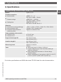
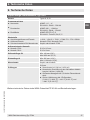
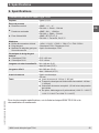
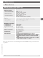
9. Specifications
Sapphire-design thermocouple, model TC84
Sensor Types S, R, B
Process connection
■
Nominal width
■
Pressure ratings
■
Sealing face
ASME: 1 ½" ... 4"
EN 1092-1: DN40 ... DN100
ASME: 300 ... 1,500 lbs
EN 1092-1: PN40 ... PN100
ASME: RF, RTJ, LT, S
EN 1092-1: Form B1, B2, E, C
Materials
■
Connection housing and flange
■
Outer protection tube
■
Protection tube material for
measuring insert
1.4541 / 1.5415 / 1.7335 / 1.7380 / F11 / F22 / SS321
Ceramic C799 / Ceramic C610
Sapphire or ceramic C799
Outer protection tube ceramic
■
Ceramic C799
■
Ceramic C610
Ø 15 x 2.5 mm
Ø 15 x 2 mm
Support tube length SL Min. 148 mm (5.8")
Max. 953 mm (37.5")
Insertion length U Min. 395 mm (15.6")
Max. 1.200 mm (47.2")
Measuring insert Sapphire or ceramic
Ø 8 mm
Tests
■
Measuring insert at 100 bar (1,450 psi)
■
Ceramic feed-through of the secondary sealing at
100 bar (1,450 psi)
■
Entire measuring instrument at 1.5 times flange
pressure rating
■
Option: Calibration at 3 test points (1,000 °C [1,832 °F],
1,100 °C [2,012 °F] and 1,200 °C [2,192 °F])
For further specifications see WIKA data sheet TE 65.84 and the order documentation.

EN
14274725.02 08/2018 EN/DE/FR/ES
WIKA operating instructions model TC8420
Seite wird geladen ...
Seite wird geladen ...
Seite wird geladen ...
Seite wird geladen ...
Seite wird geladen ...
Seite wird geladen ...
Seite wird geladen ...
Seite wird geladen ...
Seite wird geladen ...
Seite wird geladen ...
Seite wird geladen ...
Seite wird geladen ...
Seite wird geladen ...
Seite wird geladen ...
Seite wird geladen ...
Seite wird geladen ...
Seite wird geladen ...
Seite wird geladen ...
Seite wird geladen ...
Seite wird geladen ...
Seite wird geladen ...
Seite wird geladen ...
Seite wird geladen ...
Seite wird geladen ...
Seite wird geladen ...
Seite wird geladen ...
Seite wird geladen ...
Seite wird geladen ...
Seite wird geladen ...
Seite wird geladen ...
Seite wird geladen ...
Seite wird geladen ...
Seite wird geladen ...
Seite wird geladen ...
Seite wird geladen ...
Seite wird geladen ...
Seite wird geladen ...
Seite wird geladen ...
Seite wird geladen ...
Seite wird geladen ...
Seite wird geladen ...
Seite wird geladen ...
Seite wird geladen ...
Seite wird geladen ...
Seite wird geladen ...
Seite wird geladen ...
Seite wird geladen ...
Seite wird geladen ...
Seite wird geladen ...
Seite wird geladen ...
Seite wird geladen ...
Seite wird geladen ...
Seite wird geladen ...
Seite wird geladen ...
Seite wird geladen ...
Seite wird geladen ...
-
 1
1
-
 2
2
-
 3
3
-
 4
4
-
 5
5
-
 6
6
-
 7
7
-
 8
8
-
 9
9
-
 10
10
-
 11
11
-
 12
12
-
 13
13
-
 14
14
-
 15
15
-
 16
16
-
 17
17
-
 18
18
-
 19
19
-
 20
20
-
 21
21
-
 22
22
-
 23
23
-
 24
24
-
 25
25
-
 26
26
-
 27
27
-
 28
28
-
 29
29
-
 30
30
-
 31
31
-
 32
32
-
 33
33
-
 34
34
-
 35
35
-
 36
36
-
 37
37
-
 38
38
-
 39
39
-
 40
40
-
 41
41
-
 42
42
-
 43
43
-
 44
44
-
 45
45
-
 46
46
-
 47
47
-
 48
48
-
 49
49
-
 50
50
-
 51
51
-
 52
52
-
 53
53
-
 54
54
-
 55
55
-
 56
56
-
 57
57
-
 58
58
-
 59
59
-
 60
60
-
 61
61
-
 62
62
-
 63
63
-
 64
64
-
 65
65
-
 66
66
-
 67
67
-
 68
68
-
 69
69
-
 70
70
-
 71
71
-
 72
72
-
 73
73
-
 74
74
-
 75
75
-
 76
76


in anderen Sprachen
- français: WIKA TC84 Mode d'emploi
- español: WIKA TC84 Instrucciones de operación
Verwandte Artikel
-
WIKA TC90 Bedienungsanleitung
-
-
-
-
-
-
-
-
-