
2 3 4
6 7 85
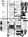
Elektrischer Anschluss
Bushaube ausschliesslich im ESD Beutel lagern und
transportieren. Bushaube muss vollständig am Gehäuse
anliegen und fest verschraubt sein.
- Beide Befestigungsschrauben der Bushaube lösen
- Bushaube vorsichtig lockern und axial abziehen.
- Teilnehmeradresse an beiden dezimalen Drehschaltern
einstellen. Teilnehmeradresse zum Beispiel 23.
- Abschlusswiderstände müssen beim letzten Teilnehmer
mit dem 1-poligen DIP Schalter auf „ON“ geschaltet
werden (Werkseinstellung OFF).
ON = Letzter Teilnehmer
OFF = Teilnehmer X
Baudrate Einstellung Dip-Schalter
1 2 3
10 kBit/s OFF OFF OFF
20 OFF OFF ON
50 OFF ON OFF
125 OFF ON ON
250 ON OFF OFF
500 ON OFF ON
800 kBit/s ON ON OFF
1 MBit/s ON ON ON
Bei Einstellung Teilnehmeradresse 00 kann die Baudrate
über den CAN-Bus programmiert werden.
Anschluss – Kabelverschraubung (Bushaube)
- Hutmutter der Kabelverschraubung lösen. Hutmutter
und Dichteinsatz auf den Kabelmantel schieben.
- Kabelmantel und Adern abisolieren, Schirmfolie, falls
vorhanden, kürzen (s. Bild).
- Schirmgeecht um ca. 90° umbiegen.
- Dichteinsatz bis an das Schirmgeecht schieben. Dicht-
einsatz und Kabel bündig in die Kabelverschraubung
einführen und Hutmutter fest verschrauben.
- Für die Betriebsspannung ausschliesslich Kabelver-
schraubung 3 verwenden.
- Für die Busleitungen können frei wählbar Kabelver-
schraubung 1 oder 2 verwendet werden. Zulässige Ka-
belquerschnitte beachten.
- Adern auf dem kürzesten Weg in die Klemmleiste
einführen, zulässiger Adernquerschnitt beachten, bei
exiblen Adern Aderendhülsen verwenden.
- Überkreuzungen der Datenleitungen mit den Leitungen
der Betriebsspannung muss vermieden werden.
- Nicht benützte Kabelverschraubung mit Verschlussbol-
zen verschliessen (Lieferumfang). Die Hutmutter muss
fest verschraubt sein.
Aderquerschnitt
Eindrahtig (starr) Max. 1,5 mm
2
Feindrahtig (exibel) Max. 1,0 mm
2
Feindrahtig (exibel) Mit Aderendhülse max. 0,75 mm
2
Kabeldurchmesser
Kabelverschraubung 1, 2 ø8...10 mm (-40...+85 °C)
ø5...9 mm (-25...+85 °C)
Kabelverschraubung 3 ø4.5...6 mm (-40...+85 °C)
ø3...6 mm (-25...+85 °C)
Anzugsdrehmoment
Klemmleiste/Schraubklemme max. 0,4 Nm
(empfohlenes Anzugsdrehmoment 0,3 Nm)
Verschraubung Bushaube max. 0,9 Nm
Kupplungsfederbefestigung max. 1,2 Nm
Klemmringbefestigung max. 1,2 Nm
Anschlussbelegung (Bushaube)
Pin 1 GND Masseanschluss für UB
Pin 2 UB Betriebsspannung 10...30 VDC
Pin 3 GND Masseanschluss für UB
Pin 4 CAN_H CAN Bus Signal (dominant High)
Pin 5 CAN_L CAN Bus Signal (dominant Low)
Klemmen mit gleicher Bezeichnung sind intern verbun-
den und funktionsidentisch. Diese internen Klemmverbin-
dungen UB-UB und GND-GND dürfen mit max. je 1 A be-
lastet werden.
Anschlussbelegung mit Inkremental-Stecker
Pin 1 A Pin 4 B inv.
Pin 2 B Pin 5 GND
Pin 3 A inv.
Anschluss – Stecker M12 (Bushaube)
Montageanleitung des Steckerlieferanten beachten.
- Steckverbinder auf Gerätestecker leicht andrücken.
- Steckverbinder vorsichtig drehen bis der Codiersteg in
die Codiernut der Steckerbuchse einrastet.
- Buchseneinsatz vollständig einführen.
- Überwurfmutter bis zum Anschlag anziehen.
Drehgeber-Gehäuse und Schirmgeecht des Anschluss-
kabels sind nur dann optimal verbunden, wenn das
Schirmgeecht grossächig im Steckverbinder auiegt
und die Überwurfmutter fest angezogen ist.
- Bushaube vorsichtig auf den D-SUB Stecker vom Ba-
sisgeber aufstecken, dann erst über den Dichtgummi
drücken und nicht verkanten. Bushaube muss vollstän-
dig am Basisgeber anliegen. Befestigungsschrauben
gleichsinnig fest anziehen. Drehgebergehäuse und
Schirmgeecht des Anschlusskabels sind nur dann opti-
mal verbunden, wenn die Bushaube vollständig auf dem
Basisgeber auiegt (Formschluss).
1
2
3
4
5
Alle beweglichen Justierelemente müssen in axialer und
radialer Richtung Spiel haben, um Verschiebungen durch
Temperatur und mechanisches Spiel auszugleichen. Be-
festigungsschrauben bzw. Schrauben des Klemmrings
fest anziehen.
Elektrische Inbetriebnahme
- Drehgeber elektrisch nicht verändern und keine Ver-
drahtungsarbeiten unter Spannung vornehmen.
- Der elektrische Anschluss darf unter Spannung nicht
aufgesteckt oder abgenommen werden.
- Bei Verbrauchern mit hohen Störpegeln separate Span-
nungsversorgung für den Drehgeber bereitstellen.
- Die gesamte Anlage EMV gerecht installieren.
Einbauumgebung und Verkabelung beeinussen die
EMV des Drehgebers. Drehgeber und Zuleitungen
räumlich getrennt oder in grossem Abstand zu Lei-
tungen mit hohem Störpegel (Frequenzumrichter,
Schütze usw.) verlegen. Drehgebergehäuse und die
Anschlusskabel vollständig schirmen.
- Drehgeber an Schutzerde (PE) anschliessen. Ge-
schirmte Kabel verwenden. Schirmgeecht muss mit der
Kabelverschraubung oder Stecker verbunden sein. An-
zustreben ist ein beidseitiger Anschluss an Schutzerde
(PE). Gehäuse über den mechanischen Anbau erden,
bei elektrisch isoliertem Anbau zusätzliche Verbindung
herstellen. Kabelschirm über die nachfolgenden an-
geschlossenen Geräte erden. Bei Problemen mit Erd-
schleifen mindestens eine einseitige Erdung.
Bei Nichtbeachtung kann es zu Fehlfunktionen, Sach-
und Personenschäden kommen.
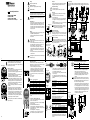
Abmessungen
Zusätzlicher
Inkremental-
Stecker
Printed in Germany · 01.18 · 178.51.149/8 · 81005123
Irrtum sowie Änderungen in Technik
und Design vorbehalten.
Subject to modication in technic and design.
Errors and omissions excepted.
Baumer IVO GmbH & Co. KG
Dauchinger Strasse 58-62
DE-78056 Villingen-Schwenningen
Phone +49 7720 942-0
Fax +49 7720 942-900
www.baumer.com
GBAMS, GBLMS, GBMMS
GCAMS, GCMMS
GXAMS, GXLMS, GXMMS
Absolute Drehgeber – CANopen 2-8
Absolute Encoder – CANopen 9-16
Montageanleitung
Assembly Instructions
DE
GB
Entsorgung
Bestandteile nach länderspezischen Vorschriften entsorgen.
Transport und Lagerung
- Ausschliesslich in Originalverpackung.
- Drehgeber nicht fallen lassen oder grösseren Erschütte-
rungen aussetzen.
Montage
- Vor Montage des Gebers, Klemmring vollständig öffnen.
- Schläge oder Schocks auf Gehäuse und Welle vermeiden.
- Gehäuse nicht verspannen.
- Drehgeber nicht öffnen oder mechanisch verändern.
- Federarme der Kupplungsfeder müssen frei beweglich sein.
- Rundlauftoleranz: Max. 0,1 mm gemessen am äus-
sersten Punkt der Antriebswelle (Motorwelle).
Hohlwelle, Kugellager, Glasscheibe oder elektro-
nische Teile können beschädigt werden. Die si-
chere Funktion ist dann nicht mehr gewährleistet.
Hohlwellen-Befestigung
Klemmringbefestigung
Drehgeber auf die Antriebswelle (ISO-Passung f7) voll-
ständig aufstecken und den Klemmring fest anziehen
(max. 1,2 Nm). Die Antriebswelle muss mindestens
35 mm in die Hohlwelle des Drehgebers eintauchen.
Mechanischer Anbau
Drehgeber über die Antriebswelle schieben und Drehmo-
mentstift in das kundenseitige Justierteil einführen oder in
das kundenseitig montierte Justierteil (mit Gummifedere-
lement) einführen.
(23.5)
(9.5)
15
3.5
ø4 fg6
Drehmomentstift
40.5
20.5
50
38
5
±0.5
1.25
Justierteil
Antriebs-
welle
Klemmring
Justierteil mit
Drehmomentstift 9.5 mm
4
2.5
22
30°
67°
25°
R37.25
R43.5
Bushaube M12
Kabelverschraubung
Gummifeder-
element
Drehmomentstift
7.585.5
ø58
33
18
ø14 H7 x 35 (ø12 H7 x 35)
ø4 fg6
24
1
6
3.5
15 (9.5)
ø42
47
20
M3 x 6 (6x)
15°
47.5
ON
1
M12-Stecker (Stift/
Buchse)
ON
1 2 3
CAN_L
CAN_H
UB
GND
CAN_L
CAN_H
UB
GND
1
2
3
4
5
1
2
3
4
5
6323
60
60
63
CAN_L
CAN_H
UB
GND
CAN_L
CAN_H
UB
GND
Bushaube M12
Kabelverschraubung
1
2
3
4
5
6
7
8
9
0
1
2
3
4
5
6
7
8
9
0
1 2 3
Ader
Schirmfolie
Dichteinsatz
Schirmgeflecht KabelHutmutter
12 Kabel
Ader
Schirmgeflecht
5 18
Gefahr
Warnung bei möglichen Gefahren.
Hinweis
Info für bestimmungsgerechte Produkthandhabung.
Allgemeiner Hinweis
Zusätzliche Informationen
Die Montageanleitung ist eine Ergänzung zu weiteren
Dokumentationen (z.B. Katalog, Datenblatt, Handbuch).
Anleitung unbedingt vor Inbetriebnahme lesen.
Bestimmungsgemässer Gebrauch
- Der Drehgeber ist ein Präzisionsmessgerät. Er dient zur
Erfassung von Winkelpositionen und Umdrehungen,
Aufbereitung und Bereitstellung von Messwerten als
elektrische Ausgangssignale für das Folgegerät. Dreh-
geber nur zu diesem Zweck verwenden.
Inbetriebnahme
- Einbau und Montage des Drehgebers darf ausschliess-
lich durch eine Fachkraft erfolgen.
- Betriebsanleitung des Maschinenherstellers beachten.
Sicherheitshinweise
- Vor Inbetriebnahme der Anlage alle elektrischen Verbin-
dungen überprüfen.
- Wenn Montage, elektrischer Anschluss oder sonstige
Arbeiten am Drehgeber und an der Anlage nicht fachge-
recht ausgeführt werden, kann es zu Fehlfunktion oder
Ausfall des Drehgebers führen.
- Eine Gefährdung von Personen, eine Beschädigung
der Anlage und eine Beschädigung von Betriebseinrich-
tungen durch den Ausfall oder Fehlfunktion des Dreh-
gebers muss durch geeignete Sicherheitsmassnahmen
ausgeschlossen werden.
- Drehgeber nicht ausserhalb der Grenzwerte betreiben,
welche im Datenblatt angegeben sind.
Bei Nichtbeachtung der Sicherheitshinweise kann es zu
Fehlfunktionen, Sach- und Personenschäden kommen.
Kupplungsfeder
Kupplungsfeder mit den Schrauben an den Befestigungslöchern des Gehäuses
montieren. Drehgeber über die Antriebswelle schieben. Kupplungsfeder an der Anla-
geäche befestigen.
7
0.3
6.6
30
40.5
7.5
53.5
M3
(1.2 Nm)
35
30
10
15.1
19.1
49.3
7.6
7.6
M3 (1.2 Nm)
SW2.5
20°
20
73
81
M3x6 (1.2 Nm)
12
M3 (1.2 Nm)
SW2.5
±0.5
20
77
68
20°
M3 (1.2 Nm)
SW2.5
12
M4x6 (1.9 Nm)
11
4.5
10.5
53.5
63.75 20.5
95.75 20.5
30
7
0.3
133.5

10 11 12
14 15 1613
9
Danger
Warnings of possible danger.
General instructions
Information on appropriate product handling.
General remarks
Additional information
The assembly instruction is supplementary to further
existing documentation (e.g. catalog, data sheet, manual).
It is imperative to read the manual carefully prior to star-
ting the device.
Appropriate use
- The encoder is a precision measuring device. It is expli-
citly designed for registration of angular positions and
revolutions as well as evaluation and supply of measu-
ring values as electric output signals for the subsequent-
ly connected device. The encoder must not be used for
any other purpose.
Start up
- Installation and assembly of the encoder only by electri-
cally skilled and qualied personnel.
- Consider also the operation manual of the machine
manufacturer.
Safety instructions
- All electrical connections are to be revised prior to star-
ting the system.
- Incorrect assembly and electrical connections or any
other inappropriate work at encoder and system may
lead to malfunction or failure of the encoder.
- Any risk of personal injury, damage of the system or
company equipment due to failure or malfunction of the
encoder has to be eliminated by corresponding safety
measures.
- Do not operate encoder beyond the limit values stated
in the data sheet.
Any disregard may lead to malfunctions, material damage
and personal injury.
GBAMS, GBLMS, GBMMS
GCAMS, GCMMS
GXAMS, GXLMS, GXMMS
Absolute Encoder – CANopen 9-16
Assembly Instructions
GB
Disposal
Encoder components are to be disposed of according to
the regulations prevailing in the respective country.
Transport and storing
- In original packing only.
- Do not drop or expose encoder to major shocks.
Assembly
- Open clamping ring completely before mounting the
encoder.
- Avoid punches or shocks on case and shaft.
- Avoid case distortion.
- Do not open or modify encoder in any mechanical way.
- The spring arm of the spring coupling has to be free
movable.
- Radial runout tolerance: 0.1 mm max., measured at the
very end of the drive shaft (motor shaft).
Hollow shaft, bearing, glass disc or electronic
components might be damaged and a secure
operation is no longer guaranteed.
Hollow shaft mounting
Mounting with clamping ring
Plug encoder completely onto drive shaft (ISO-t f7) and tigh-
ten clamping ring rmly (max. 1.2 Nm). The drive shaft must
penetrate the encoder’s hollow shaft to a depth of 35 mm.
Mechanical assembly
Slide encoder onto the drive shaft and insert torque pin
into the adjusting element provided by customer or insert
pin into the mounted adusting part (with rubber spring ele-
ment) provided by customer.
drive
shaft
clamping ring
(23.5)
(9.5)
15
3.5
ø4 fg6
torque pin
40.5
20.5
50
38
5
±0.5
1.25
adjustment
piece
rubber spring
element
adjustment piece with
torque pin 9.5 mm
4
2.5
22
30°
67°
25°
R37.25
R43.5
torque pin
Electrical connection
The bus cover is to be stored and transported whilst in
the ESD bag only. The bus cover has to t the case tightly
and has to be rmly secured by screws.
- Unscrew both xing screws of the bus cover.
- Loosen bus cover carefully and remove it in axial direction.
- Adjust participant address at the two decimal rotary
switches. The participant’s address for example 23.
- For the last participant the terminators are to be swit-
ched “ON” by means of the 1-pin Dip switch (default
OFF).
ON = nal user
OFF = user X
Baud rate Dip switch position
1 2 3
10 kBit/s OFF OFF OFF
20 OFF OFF ON
50 OFF ON OFF
125 OFF ON ON
250 ON OFF OFF
500 ON OFF ON
800 kBit/s ON ON OFF
1 MBit/s ON ON ON
If the user address 00 the baud rate is programmable via
CAN bus.
Connection – cable gland (bus cover)
- Unscrew cap nut of cable gland. Push cap nut and seal
insertion onto the cable coat.
- Strip isolation of cable coat and cores and cut shielding
foil, if any (picture).
- Bend the braided shield for about 90°.
- Push seal insertion to the braided shield. Insert seal
and cable ush into the cable gland. Secure by carefully
tightening the cap nut.
- Use cable gland no. 3 for supply only.
- Cable glands no. 1 and 2 are for optional use as bus
lines. Consider the permitted cable cross-section.
- Use the shortest way to insert the cores into the termi-
nals and mind the maximum core cross-section. Use
core tip sleeves with exible cores.
- There must not be any crossing of data lines with lines
for power supply.
- Any cable gland not used has to be sealed by blind
plug (included into delivery). The cap nut must be rmly
tightened.
Core cross-section
Single wire (rigid) Max. 1.5 mm
2
Fine wire (exible) Max. 1.0 mm
2
Fine wire (exible) With ferrule max. 0.75 mm
2
Cable diameter
Cable gland 1, 2 ø8...10 mm (-40...+85 °C)
ø5...9 mm (-25...+85 °C)
Cable gland 3 ø4.5...6 mm (-40...+85 °C)
ø3...6 mm (-25...+85 °C)
Locking torque
Terminal strip/screwing terminal max. 0.4 Nm
(recommended locking torque 0.3 Nm)
Connection bus cover max. 0.9 Nm
Spring coupling mounting max. 1.2 Nm
Clamping ring mounting max. 1.2 Nm
Terminal assignment (bus cover)
Pin 1 GND Ground connection relating to UB
Pin 2 UB Supply voltage 10...30 VDC
Pin 3 GND Ground connection relating to UB
Pin 4 CAN_H CAN bus signal (dominant High)
Pin 5 CAN_L CAN bus signal (dominant Low)
Terminals of the same signicance are internally con-
nected and identical in their functions. Max. load on the
internal terminal connections UB-UB and GND-GND is
1 A each.
Terminal assignment incremental connector
Pin 1 A Pin 4 B inv.
Pin 2 B Pin 5 GND
Pin 3 A inv.
Assignment – connector M12 (bus cover)
Follow also the instructions of the respective supplier.
- Press mating connector softly into the plug.
- Turn mating connector carefully until the code mark is
interlocking the corresponding space provided by the plug.
- Insert bushing completely. Tighten the nut as far as
possible.
An optimized connection between encoder case and the
braided shield of the connection cable is only achieved by
the braided shield being placed generously onto the con-
nector and the nut being secured rmly.
- Plug the bus cover carefully onto the D-SUB plug of the
basic encoder, then push it over the rubber seal. Avoid
the case getting wedged. The bus cover has to t tightly
the basic encoder. Tighten both xing screws rmly and
conformable. An optimized connection between encoder
case and the braiding shield of the supply cable is only
achieved by a complete and close t of the bus cover
onto the basic encoder (interlock).
1
2
3
4
5
All movable adjusting elements need tolerance in both
axial and radial direction in order to equalize shifts by
temperature and of mechanical nature. Tighten both xing
and clamp ring screws rmly.
Electrical installation
- Do not modify encoder in any electrical way and carry
out any wiring work under power supply.
- Any electrical connection and plugging-on whilst under
power supply is not permitted.
- A separate encoder supply has to be provided with con-
sumers with high interference emission.
- Installation of the whole system has to be according
to EMC standards. Installation environment as well as
wiring have an impact on the encoder’s EMC. Encoder
and supplying lines are to be in separated locations or
remote from lines with high interference emission (fre-
quency transformers, protections, etc.).
- Encoder case and supply cable have to be completely
screened.
- Ground (PE) encoder by using screened cables. The
braided shield has to be connected to cable gland or
plug. Grounding (PE) on both sides is recommended.
Ground the case by the mechanical assembly, if latter
is electrically isolated a second connection has to be
provided. Ground cable screen by the subsequently
connected devices. In case of ground loop problems at
least grounding on one side is imperative.
Any disregard may lead to malfunctions, material damage
and personal injury.
Dimensions
7.585.5
ø58
33
18
ø14 H7 x 35 (ø12 H7 x 35)
ø4 fg6
24
1
6
3.5
15 (9.5)
ø42
47
20
M3 x 6 (6x)
15°
47.5
Additional
incremental
connector
60
63
Bus cover M12
6323
60
Cable gland
ON
1 2 3
CAN_L
CAN_H
UB
GND
CAN_L
CAN_H
UB
GND
CAN_L
CAN_H
UB
GND
CAN_L
CAN_H
UB
GND
Bus cover M12
Cable gland
M12 connector (male/
female)
1
2
3
4
5
1
2
3
4
5
1
2
3
4
5
6
7
8
9
0
1
2
3
4
5
6
7
8
9
0
cablecap nut
wire
screen film
seal
screen
12 Cable
Wire
Screen
5 18
1 2 3
Spring coupling
Fasten spring coupling at the xing holes provided on housing by means of screws.
Slide encoder onto the drive shaft and fasten spring coupling at the surface provided
with screws.
7
0.3
6.6
30
40.5
7.5
53.5
M3
(1.2 Nm)
35
30
10
15.1
19.1
49.3
7.6
7.6
M3 (1.2 Nm)
SW2.5
20°
20
73
81
M3x6 (1.2 Nm)
12
M3 (1.2 Nm)
SW2.5
±0.5
20
77
68
20°
M3 (1.2 Nm)
SW2.5
12
M4x6 (1.9 Nm)
11
4.5
10.5
53.5
63.75 20.5
95.75 20.5
30
7
0.3
133.5
ON
1
-
 1
1
-
 2
2


Baumer GXMMS Installation and Operating Instructions
- Typ
- Installation and Operating Instructions
- Dieses Handbuch eignet sich auch für
in anderen Sprachen
- English: Baumer GXMMS
Verwandte Artikel
-
Baumer GBAMS Installation and Operating Instructions
-
Baumer GBMMH Installation and Operating Instructions
-
-
-
-
-
-
-
-