KPS DCM7000BT Bedienungsanleitung
- Kategorie
- Kabelnetzwerktester
- Typ
- Bedienungsanleitung

IT
EN
User Manual / MANUAL DEL USUARIO /
Manuel d'utilisation / Benutzerhandbuch /
Manuale Utente
DCM7000BT
All New Designed Bluetooth Clamp Meter
Pinza amperimétrica bluetooth con nuevo diseño
Toute nouvelle pince ampèremétrique Bluetooth
Ganz neu entwickeltes Bluetooth-Zangenmessgerät
Una Pinza Amperometrica Bluetooth di progettazione assolutamente nuova
LIMITED
WARRANTY
YEARS

EN
DCM7000BT
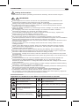
Symbols as marked on the Meter and Instruction manual
!Safety Information
Understand and follow operating instructions carefully. Use the meter only as .
WARNING
!
If the equipment is used in a manner not specified by themanufacturer, the
protection provided by the equipment may be impaired.
Always use proper terminals, switch position, and range for measurements.
To reduce the risk of fire or electric shock, do not use this product around
explosive gas or in damp locations.
Verify the Meter operation by measuring a known voltage. If in doubt, have the
Meter serviced.
Do not apply more than the rated voltage, as marked on Meter, between
terminals or between any terminal and earth ground.
To avoid false readings that can lead to electric shock and injury, replace the
battery as soon as low battery indicator blinks.
Avoid working alone so assistance can be rendered.
Do not use the Tester if the Tester is not operating properly or if it is wet.
Individual protective device must be used if hazardous live parts in the installation
where the measurement is to be carried out could be accessible.
Disconnect the test leads from the test points before changing the position of the
function rotary switch.
Never connect a source of voltage when the function rotary switch is not in
voltage position.
When using test leads or probes, keep your fingers behind the finger guards.
Use caution with voltages above 30 Vac rms, 42 Vac peak, or 60 Vdc. These
voltages pose a shock hazard.
Remove test lead from Meter before opening the battery door or Meter case.
DO NOT USE the test leads when the internal white insulation layer is exposed.
DO NOT USE the test leads above maximum ratings of CAT.
environment, voltage and current, that are indicated on the probe and the probe
tip guard cap.
DO NOT USE the test leads without the probe tip guard cap in CAT III and CAT IV
environments.
Probe assemblies to be used for MAINS measurements shall be RATED as
appropriate for MEASUREMENT CATEGORY III or IV according to IEC
61010-031 and shall have a voltage RATING of at least the voltage of the circuit
to be measured.
Disconnect circuit power and discharge all high-voltage capacitors before testing
resistance, continuity, diodes, or capacitance.
De-energize the installation under test or wear suitable protective clothing during
fitting and removal of the Flexible Current Probe.
Do not apply around or remove from UNINSULATED HAZARDOUS LIVE
conductors, which may render electric shock, electric burn, or arc flash.
Do not apply a current with frequency that is higher than the frequency response
range specified in the Electrical specification section.
!
Risk of electric shock
Equipment protected by
double or reinforced
insulation
DC measurement
Low battery
Earth ground
AC measurement
Both direct and alternating currentWireless transmission
Conforms to EU directivesApplication around and
removal from hazardous
live conductors is permitted
See instruction manual
~
~
—
Do not discard this product or
throw away.
01

EN
DCM7000BT
Maintenance
Do not attempt to repair this Meter. It contains no user serviceableparts. Repair or
servicing should only be performed by qualified personnel.
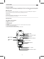
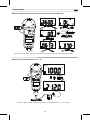
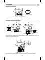
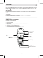
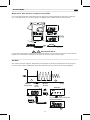
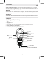
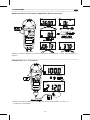
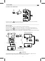
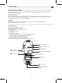
Front Panel Illustration
1. JAW
2. Volt seek Light.
3. Push-buttons.
4. Trigger.
5. Rotary switch for turn the Power On / Off and select the function.
6. 6,000 count digital display.
7. Input Terminal for Multi-function.
8. Common (Ground reference) Input Terminal.
Cleaning
Periodically wipe the case with a dry cloth and detergent.
Do not use abrasives or solvents.
Introduction
The Meter Description
Unsafe Voltage
To alert you to the presence of a potentially hazardous voltage,when the Tester detects
a voltage 30 V or a voltage overload (OL) in V, mV, LoZ. The symbol is displayed.
1
2
3
5
6
7
4
3
8
JAW
Voltseek Light
Button
Rotary Switch
Display
"+" Input
Trigger
Button
Common input
Function button
02

EN
DCM7000BT
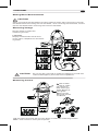
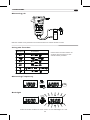
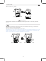
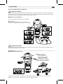
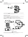
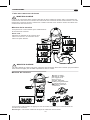
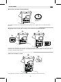
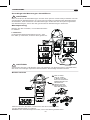
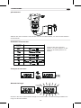
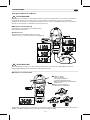
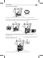
!CAUTION
When connecting the test leads to the DUT (Device Under Test) connect the common
test leads before connecting the live test leads ; when removing the test leads, remove
the live test leads before removing the common test leads.
Dial the switch to select the
measuring function.
LoZ mode :
Display measurement result at AC
or DC value, it depends on whichever
is greater.
!CAUTION Do not use the LoZ mode to measure voltages in circuits that
could be damaged by this mode’s low impedance.
V
APO AC
V
APO
APO
DC
DC
mV
V
APO AC
LOZ
APO
DC
LOZ
COM
Measuring Voltage
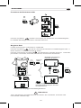
Measuring Current
OK OK
OK
I
CAT.IV 600V
CAT.III 1000V
with respect to
earth for the jaw.
Tactile Barrier for
hand guard.
Do not hold
the meter across
the Barrier
!
!
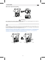
Dial the switch and press the Function button to select the measuring function.
Note : Torch will be on when jaw is opened.
Making Basic Measurements
03

EN
DCM7000BT
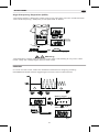
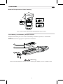
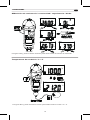
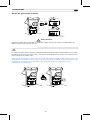
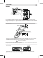
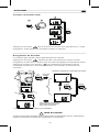
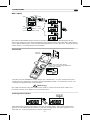
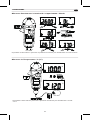
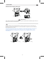
Dial the switch and press the Function button to select the measuring function.
Dial the switch and press the Function button to select °C / °F mode.
Measuring Resistance/Continuity/Capacitance/Diode
Measuring Temperature °C / °F
APO APO
k
APO
Volt seek
APO
V
APO
F
COM
APO
APO
C
F
Funtion
Button
COM
04

EN
DCM7000BT
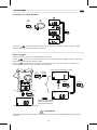
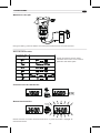
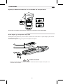
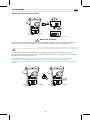
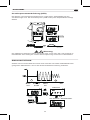
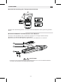
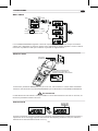
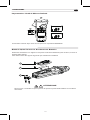
Dial the switch and press the Function button to select AC/DC mode.
Press Function button for over 2 sec. to turn Backlight on / off.
Press the Function button to
change the function on the
same switch position.
Measuring μA
Using the Function
Measuring Frequency
Backlight
DC
AFlame
sensor
Control
Module
Switch
Position Function
°°
Funtion
Button
AC AC
V
Hz Hz
2 Sec
> 2 sec
Press
05

EN
DCM7000BT
MIN/MAX
Volt Seek
Smart Hold
MIN
MAX
MIN
MAX
V
V
AC
V
MIN
MAX
Press
MIN
MAX
Press
MAX MIN AC
MIN
MAX
AC
Press MIN
MAX Button > 2 sec
to exit the MINMAX mode
V
AC
Press
MIN
MAX
Press
The MAX/MIN mode records the min and max input values.
When the input goes below the recorded min value or above the recorded max value,
the meter records the new value. Press Hold button to pause the recording.
Press MIN/MAX button for over 2 sec. to enter / exit Volt Seek mode.
Press MIN/MAX button to switch high/low sensitivity.
!Warning
The Volt Seek LED indicates the electric field. If the Volt Seek LED is not on, voltage
could still be present.
The meter will beep continuously and the display will flash if the measured signal is
larger than the display reading by 50 counts.
(However, it can not detect across the AC and DC Voltage / Current).
MIN
MAX
MIN
MAX
AC
Volt seek
2 Sec
Volt seek
2 Sec
Do not hold across this
line when sensing the
hazardous voltage.
COM
Sensor
position
AC AC
HOLD
ZERO
A A
HOLD
HOLD
06

EN
DCM7000BT
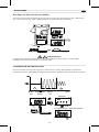
High Frequency Rejection (HFR)
The High Frequency Rejection mode equip a low pass filter in the AC measurements.
The cut-off frequency (-3dB point) of low pass filter is 800Hz.
INRUSH
In inrush current mode, select the suitable measurement range by pressing
HFR/INRUSH button before triggering the inrush current measurement.
HFR
HFR
AC
AC
HFR
Press
HFR
V
V
!Warning
The hazardous voltage may be present even if the LCD reading is very low in HFR
mode. Verify the voltage again without HFR mode
12
A A
A
HFR
> 2 sec
Press
Watting Tigger
After Tigger
1
2
Inrush
2 Sec
HFR
> 2 sec
Press
Inrush
2 Sec
AC AC
AC
07

EN
DCM7000BT
Auto Power Off
Time Setting of Auto Power Off
Testing LCD Monitor
Wake up the meter by dialing the switch or pressing any button.
Press the function button and turn the meter on. Then press the function button to
select the time. The time can be 5 minutes, 10 minutes, 20 minutes, and disabled
(OFF).
To turn on the meter after keeping HOLD button down.
After Specified Time
Without Operation
Funtion
Button
1
2 3
Funtion
Button
APO
HOLD
1
2
APO Zero MAX MIN HOLDAC
LOG HFR LOZ DC%
S°C°F
FA
mV
Hz
k
08

EN
DCM7000BT
Data Logger
Function of LOG Button
Press
1 2
3
Press
LOG
LOG
LOG
Press
Press
Pressing button while powering-up to select the mode – Data Logger mode,
Manual Saving mode and Clear memory.
The meter can store up to 4000 data in memory.
Press button for more than 2 seconds to activate Data logger mode. The meter
will enter Time interval setting mode.
Press button again to select time interval. The interval can be 1 second, 5
seconds, 10 seconds, 30 seconds, 60 seconds.
LOG
2 Sec
AC
V
Press
Press Press
LOG
LOG
S
S
V
AC
LOG
Press
Time interval setting mode
Start to record auto
matically after 2sec
without operaction.
LOG icon flashes while logging
LOG
2 Sec >2Sec
!CAUTION
All stored data will be cleared next startup. Download the stored data by App first if
needed.
09

EN
DCM7000BT
Manual Saving Mode
The meter uses Wireless low energy (BLE) V4.0 wireless technology to transfer the
real-time reading and the stored data.
The open-air communication range is up to 10m.
Download “KPS Link” App via the following QR Code. Turn on Bluetooth function of the
meter and open “KPS Link” to connect the DMM. The Bluetooth icon of the meter will
freeze on LCD after the connection establishes successfully.
!CAUTION
All stored data are saved until switching to data logger mode or executing the clear
function.
AC
Press
AC
VV
LOG
2 Sec
AC
V
LOG
V
AC
LOG
To save a reading
Show stored reading
amount for 2 seconds
HOLD
LOG Flash
Press
LOG
2 Sec
>2Sec
10

EN
DCM7000BT
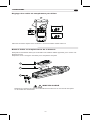
Replace the battery as soon as the low battery indicator appears, to avoid false
reading.
Refer to the following figure to replace the batteries
1
2
3
Default Temperature Units Setting
Low Battery and Battery Replacement
!Warning
Remove test leads from Meter before opening the battery cover or Meter case.
Turn on the meter after keeping MIN/MAX button down.
C
F
OR
1
2
COM
MIN
MAX
MIN
MAX
11

EN
DCM7000BT
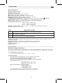
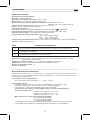
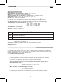
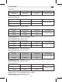
(1) Temperature coefficient
0.2 x (Specified accuracy) / °C, < 18°C, > 28°C
(2) AC Function
ACV and ACA specifications are ac coupled, true R.M.S.
The crest factor may be up to 3.0 as 4000 counts.
Accuracy is unspecified of Square Wave.
For non-sinusoidal waveforms, Additional Accuracy by
Crest Factor (C.F.) :
Add 3.0% for C.F. 1.0 ~ 2.0.
Add 5.0% for C.F. 2.0 ~ 2.5.
Add 7.0% for C.F. 2.5 ~ 3.0.
Max. Crest Factor of Input Signal:
3.0 @ 3000 counts
2.0 @ 4500 counts
1.5 @ 6000 counts
Frequency Response is specified for sine waveform.
LCD displays 0 counts when the reading < 20 counts.
Specifications
CAT Application field
General Specifications
Display : 6000 counts.
Overrange Indication : ”OL” or “-OL”
Measure : Samples 3 times per second .
Max Conductor Size of JAW : 37mm diameter
Dimensions (W x H x D) : 62mm x 240mm x 41mm
Weight : approx. 430g (including battery)
Low Batteries Indication : Voltage drops below operating voltage will flash.
Power Requirement : AA Size Battery x 2 (R6, LR6, 15D, 15A)
Battery Life : 300 hours ALKALINE Battery (without Backlight)
Operating Temperature : -10 ~10°C
10°C ~ 30°C ( 80% RH),
30°C ~ 40°C ( 75% RH),
40°C ~ 50°C ( 45%RH)
Storage Temperature : -20°C to 60°C , 0 to 80% R.H. (batteries not fitted)
Altitude : 6561.7 ft (2000m)
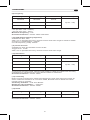
Electrical Specifications
Accuracy is given as ± (% of reading + counts of least significant digit) at 23°C ± 5°C,
with relative humidity Less than 80% R.H., and is specified for 1 year after calibration.
Safety : EN 61010-1, EN 61010-2-032, EN 61010-2-033 for CAT III 1000V, CAT IV
600V, EN 61326-1
Drop Protection : 4 feet drop to hardwood on concrete floor
Vibration : Random Vibration per MIL-PRF-28800F Class 2
Pollution degree : 2
Indoor Use
The building installation.
The circuits directly connected to Low-voltage installation.
The source of the Low-voltage installation.
12

EN
DCM7000BT
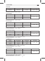
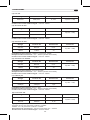
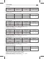
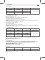
(3) DC mV
Input Impedance : 10MΩ
Overload Protection : AC/DC 1000V
Range OL Reading Resolution Accuracy
600.0mV 660.0mV 0.1mV ± (0.7% + 5D)
(4) DC Voltage
Input Impedance : 10MΩ
Overload Protection : AC/DC 1000V
Range OL Reading Resolution Accuracy
660.0V 660.0V 0.1V
1000V 1100V 1V
±(0.7% + 2D)
(5) AC Voltage
Input Impedance : 10MΩ // less than 100pF
Frequency Response : 45 ~ 400Hz (Sine Wave)
Overload Protection : AC/DC 1000V
Range OL Reading Resolution Accuracy
600.0V 660.0V 0.1V
1000V 1100V 1V
±(1.0% + 5D)
(6) LoZ AC/DC Voltage
Input Impedance : less than 3kΩ
Frequency Response : 45 ~ 400Hz (Sine Wave)
Overload Protection : AC/DC 1000V
Range OL Reading Resolution Accuracy
600.0V 660.0V 0.1V
1000V 1100V 1V
±(2.0% + 5D)
(7) AC/DC μA
Input Impedance : Approx. 2.2kΩ
Frequency Response : 45 ~ 400Hz (Sine Wave)
Overload Protection : AC/DC 1000V
Range OL Reading Resolution Accuracy
400.0μA 440.0μA 0.1μA
4000μA 4400μA 1μA
±(1.0% + 3D)
(8) AC Current
Add 10 dgt to the accuracy when <5.0A.
Add 1% to the accuracy when >100Hz.
Frequency Response : (Sine Wave) 45 ~ 400Hz
Overload Protection : AC/DC 600A
Range OL Reading Resolution Accuracy
60.00A 66.00A 0.01A
600.0A 660.0A 0.1A
±(2.0% + 5D)
13

EN
DCM7000BT
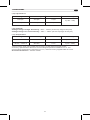
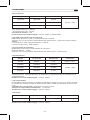
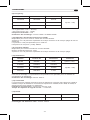
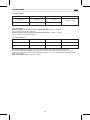
(9) Frequency
Minimum Sensitivity :
> 5V (for ACV 1Hz ~ 10kHz)
> 8A (for ACA 1Hz ~ 1kHz)
Minimum Frequency : 1Hz
Overload Protection : AC/DC 1000V and 600A
(10) HFR (High Frequency Rejection)
Available for ACV, ACA
Add ± 4% to specified accuracy of each function and each range for 45Hz to 200Hz.
Accuracy is unspecified for > 200Hz.
Cut-off Frequency (-3dB) : 800Hz
(11) Inrush Current
Available for ACA and Flexible Current Probe.
Trigger level : 50d.
Add ± 3% to specified accuracy of each function and each range.
Range OL Reading Resolution Accuracy
100.00Hz 100.00Hz 0.01Hz
1000.0Hz 1000.0Hz 0.1Hz
10.000kHz 10.000kHz 0.001kHz
±(0.3% + 3D)
(12) Resistance
To get more accuracy result, short the test probes to obtain the offset. The accuracy
specification is specified for the result that the offset is subtracted.
Overload Protection : AC/DC 1000V
(13) Continuity
Built-in buzzer sounds when measured resistance is less than 20Ω and sounds off
when measured resistance is more than 200Ω, Between 20Ω to 200Ω the buzzer
maybe sound or off either.
Continuity Indicator : 2.7K Tone Buzzer
Response Time of Buzzer : < 100msec.
Overload Protection : AC/DC 1000V
Open Circuit Voltage : Approx. 1.8V
Overload Protection : AC/DC 1000V.
Range OL Reading Resolution Accuracy
600.0Ω 660.0Ω 0.1Ω ±(0.9% + 5D)
6.000kΩ 6.600kΩ 0.001kΩ
600.0kΩ 660.0kΩ 0.1kΩ
60.00kΩ 66.00kΩ 0.00kΩ ±(0.9% + 2D)
(14) Diode
Range OL Reading Resolution Accuracy
1.500V 1.550V 0.001V ±(0.9% + 2D)
14

EN
DCM7000BT
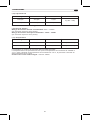
(15) Capacitance
Range OL Reading Resolution Accuracy
100.0μF 110.0μF 0.1μF
1000μF 1100μF 1μF
±(1.9% + 2D)
(17) Temperature
Range OL Reading Resolution Accuracy
-40.0°C – 400.0°C 440.0°C 0.1°C
-40.0°F – 752.0°F 824.0°F 0.1°F
±(1% + 20D)
±(1% + 36D)
Overload Protection : AC/DC 1000V
(16) VoltSeek
Voltage Range of High Sensitivity : 80V ~ 1000V (At the top edge of the jaw)
Voltage Range of Low Sensitivity : 160V ~ 1000V (At the top edge of the jaw)
The accuracy does not include the accuracy of the thermocouple probe.
Accuracy specification assumes surrounding temperature stable to ±1°C. For
surrounding temperature changes of ± 2°C, rated accuracy applies after 2 hours.
Overload Protection : AC/DC 1000V
15

DCM7000BT
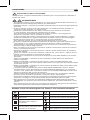
!Información de seguridad
Comprenda y siga cuidadosamente las instrucciones de funcionamiento. Utilícelos
solamente como se le indique.
ADVERTENCIA
!
Si el equipo se utiliza de una manera no especificada por el fabricante, la
protección proporcionada por el equipo puede estar deteriorado.
Utilice siempre las termináis adecuadas, la posición del interruptor y el rango para
Medidas.
Para reducir el riesgo de incendio o descarga eléctrica, no utilice producto
alrededor de gas explosivo o en lugares húmedos.
Verifique el funcionamiento del medidor midiendo un tensión conocido.
En caso de duda, que el medidor sea atendido.
No aplique más que la tensión nominal, como se marca en Medidor, entre
terminales o entre cualquier terminal y tierra.
Para evitar lecturas falsas que pueden provocar descargas eléctricas y lesión,
reemplace las pilas tan pronto como parpadee el indicador de pila baja.
Evite trabajar solo para que se pueda prestar asistencia.
No utilice el probador si el probador no funciona correctamente o si está mojado.
Se debe utilizar un dispositivo de protección individual si partes de la instalación
donde se va a llevar la medición fuera podría ser accesible.
Desconecte los cables de prueba de los puntos de prueba antes de cambiar la
posición del interruptor giratorio de la función.
Nunca conecte una fuente de tensión cuando la función giratoria interruptor no está
en posición de tensión.
Cuando utilice cables de prueba o sondas, mantenga los dedos detrás los guardias
de los dedos.
Tenga cuidado con las tensiones superiores a 30 Vac rms, pico de 42 VCA o 60
Vdc. Estas tensiones representan un peligro de choque.
Retire el cable de prueba de Meter antes de abrir la puerta de las pilas o caso del
medidor.
NO UTILICE los cables de prueba cuando la capa de aislamiento blanco interno
está expuesta.
NO UTILICE los cables de prueba por encima de las clasificaciones máximas de
CAT. de ambiente, tensión y corriente, según se indican en la sonda y la tapa del
protector de la punta de la sonda.
NO UTILICE los cables de prueba sin la tapa del protector de la punta de la sonda
en los entornos CAT III y CAT IV.
Los conjuntos de sondas que se utilizarán para mediciones MAINS se clasificarán
según proceda para la MEDICIÓN CATEGORÍA III o IV según IEC 61010-031 y
tendrán una clasificación de tensión de al menos la tensión del circuito a medir.
Desconecte la potencia del circuito y descargue todos los capacitores de alta
tensión antes de probar resistencia, continuidad, diodos o capacitancia.
Desactive la instalación bajo prueba o use ropa protectora adecuada durante el
montaje y la eliminación de la sonda flexible de corriente.
No aplicar alrededor o quitar de los conductores PELIGROSOS LIVE NO
INAPULADOS, que pueden hacer que la descarga eléctrica, la combustión eléctrica
o el arco parpadee.
No aplique una corriente con una frecuencia superior al rango de respuesta de
frecuencia especificado en la sección Específico eléctrico.
Símbolos marcados en el manual de medidores e instrucciones
!
Riesgo de descarga eléctrica
Equipos protegidos por
aislamiento doble o
reforzado
Medición CC
Pila baja
Tierra
Medición CA
Corriente directa y alternaBluetooth
Se ajusta a las directivas de la UESe permite la aplicación y
eliminación de conductores
vivos peligrosos
Consulte el manual de instrucciones
~
~
—
No deseche ni tire este producto
ES
16

DCM7000BT
Mantenimiento
No intente reparar este medidor. No contiene piezas de servicio de usuario. La
reparación o el servicio solo deben ser realizados por personal cualificado.
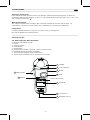
Ilustración del panel frontal
1. Pinza
2. Volt busca luz.
3. Pulsadores.
4. Disparador.
5. Dial para encender / apagar y seleccionar función.
6. Pantalla digital de 6,000 unidades.
7. Terminal de entrada para multifunción.
8. Terminal de entrada común (referencia a tierra).
Limpieza
Limpie periódicamente la caja con un paño seco y detergente.
No utilice abrasivos ni disolventes.
Introducción
La descripción del medidor
Tensión insegura
Para alertarle de la presencia de una tensión potencialmente peligrosa, cuando el
Probador detecta una tensión 30 V o una sobrecarga de tensión (OL) en V, mV, LoZ.
Se muestra el símbolo .
1
2
3
5
6
7
4
3
8
PINZA
Luz Voltseek
Botón
Dial
Pantalla
Entrada "+"
Disparador
Botón
Entrada común
botón de función
ES
17

ES
DCM7000BT
!PRECAUCIÓN
Al conectar las puntas de prueba al dispositivo a prueba (DAP), conecte la punta de
prueba común antes de conectar la fase. al quitar las puntas de prueba, retire la fase
de prueba antes de quitar la punta de prueba común.
Ponga el dial en la función de medición.
Modo LoZ :
Muestra el resultado de la medición en
CA o CC, dependiendo del que sea mayor.
!PRECAUCIÓN
No utilice el modo LoZ para medir tensiones en circuitos que puedan dañarse por la
baja impedancia de este modo.
V
APO AC
V
APO
APO
DC
DC
mV
V
APO AC
LOZ
APO
DC
LOZ
COM
Medición de tensión
Misurare la Corrente
OK OK
OK
I
CAAT.IV 600V
CAT.III 1000V
con respecto a la
tierra para la pinza.
Barrera táctil para
preteger las manos.
No sujete el medidor
más allá de la barrera
!
!
Ponga el dial y pulse el botón Función para seleccionar la función de medición.
Nota : La linterna se enciende cuando se abre la pinza.
Hacer mediciones básicas
18

ES
DCM7000BT
Ponga el dial y pulse el botón Función para seleccionar la función de medición.
Ponga el dial y pulse el botón Función para seleccionar el modo °C / °F.
MMedición de resistencia / continuidad / capacitancia / diodo
Temperatura de medición °C / °F
APO APO
k
APO
Volt seek
APO
V
APO
F
COM
APO
APO
C
F
Funtion
Button
COM
19
Seite laden ...
Seite laden ...
Seite laden ...
Seite laden ...
Seite laden ...
Seite laden ...
Seite laden ...
Seite laden ...
Seite laden ...
Seite laden ...
Seite laden ...
Seite laden ...
Seite laden ...
Seite laden ...
Seite laden ...
Seite laden ...
Seite laden ...
Seite laden ...
Seite laden ...
Seite laden ...
Seite laden ...
Seite laden ...
Seite laden ...
Seite laden ...
Seite laden ...
Seite laden ...
Seite laden ...
Seite laden ...
Seite laden ...
Seite laden ...
Seite laden ...
Seite laden ...
Seite laden ...
Seite laden ...
Seite laden ...
Seite laden ...
Seite laden ...
Seite laden ...
Seite laden ...
Seite laden ...
Seite laden ...
Seite laden ...
Seite laden ...
Seite laden ...
Seite laden ...
Seite laden ...
Seite laden ...
Seite laden ...
Seite laden ...
Seite laden ...
Seite laden ...
Seite laden ...
Seite laden ...
Seite laden ...
Seite laden ...
Seite laden ...
Seite laden ...
Seite laden ...
-
 1
1
-
 2
2
-
 3
3
-
 4
4
-
 5
5
-
 6
6
-
 7
7
-
 8
8
-
 9
9
-
 10
10
-
 11
11
-
 12
12
-
 13
13
-
 14
14
-
 15
15
-
 16
16
-
 17
17
-
 18
18
-
 19
19
-
 20
20
-
 21
21
-
 22
22
-
 23
23
-
 24
24
-
 25
25
-
 26
26
-
 27
27
-
 28
28
-
 29
29
-
 30
30
-
 31
31
-
 32
32
-
 33
33
-
 34
34
-
 35
35
-
 36
36
-
 37
37
-
 38
38
-
 39
39
-
 40
40
-
 41
41
-
 42
42
-
 43
43
-
 44
44
-
 45
45
-
 46
46
-
 47
47
-
 48
48
-
 49
49
-
 50
50
-
 51
51
-
 52
52
-
 53
53
-
 54
54
-
 55
55
-
 56
56
-
 57
57
-
 58
58
-
 59
59
-
 60
60
-
 61
61
-
 62
62
-
 63
63
-
 64
64
-
 65
65
-
 66
66
-
 67
67
-
 68
68
-
 69
69
-
 70
70
-
 71
71
-
 72
72
-
 73
73
-
 74
74
-
 75
75
-
 76
76
-
 77
77
-
 78
78


KPS DCM7000BT Bedienungsanleitung
- Kategorie
- Kabelnetzwerktester
- Typ
- Bedienungsanleitung
in anderen Sprachen
- français: KPS DCM7000BT Le manuel du propriétaire
- español: KPS DCM7000BT El manual del propietario
- italiano: KPS DCM7000BT Manuale del proprietario
Verwandte Papiere
Sonstige Unterlagen
-
DirekTronik 20115417 Bedienungsanleitung
-
Greenlee CMI-2000 Benutzerhandbuch
-
Amprobe ACD-50 Series Benutzerhandbuch
-
 Wavetek Meterman Meterman 220 Benutzerhandbuch
-
 Wavetek Meterman 235 Bedienungsanleitung
-
-
METREL MD 9250 Benutzerhandbuch
-
 Chauvin-Arnoux CA-L111 Bedienungsanleitung
-
John Deere SW16136 Benutzerhandbuch
-
 Chauvin-Arnoux CA-PEL105 Bedienungsanleitung


