
CenterBase 2
DE
02
EN
05
NL
08
DA
11
FR
ES
IT
PL
FI
PT
SV
14
17
20
23
NO
TR
RU
UK
CS
ET
LV
LT
RO
BG
EL
26
50
29
53
32
56
35
59
38
62
41
65
44
47

DE
02
1
2
5
4
8
9
3
6
7
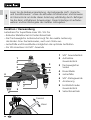
Lesen Sie die Bedienungsanleitung, das beiliegende Heft „Garantie-
und Zusatzhinweise“ sowie die aktuellen Informationen und Hinweise
im Internet-Link am Ende dieser Anleitung vollständig durch. Befolgen
Sie die darin enthaltenen Anweisungen. Diese Unterlage ist aufzube-
wahren und bei Weitergabe des Gerätes mitzugeben.
!
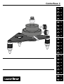
Funktion / Verwendung
Justierbasis für SuperPlane-Laser 3D / 3G Pro
– Robuster Metallsockel mit Seitenfeinantrieb
– Der frei bewegliche Justiersockel sorgt für die exakte Justierung
des Boden- bzw. Deckenkreuzes, auch vom Stativ aus.
– Justierfüße und Dosenlibelle ermöglichen das optimale Aufstellen.
– Für 3D-Linienlaser mit 5/8“-Gewinde
1
2
3
4
5
6
7
8
9
5/8“ Gewindestück
Aufnahme
Gewindestück
frei beweglicher
Sockel
Dosenlibelle
Justierfüße
5/8“-Stativgewinde
Arretierung
Feststellschraube
Gewindestück
Seitenfeinantrieb
Lösen
Fixieren

DE
CenterBase 2
03
1.
2.
3.
4.
5.
6.
1.
2.
3.
SuperPlane-Laser 3D Pro
SuperPlane-Laser 3D Pro
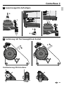
1Lasermessgeräte befestigen
2Justierung mit frei beweglichem Sockel
Positionierung 3D-Linienlaser

DE
04
SuperPlane-Laser 3D Pro
SuperPlane-Laser 3D Pro
SuperPlane-Laser 3D Pro
~72 mm
~40 mm
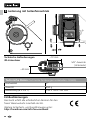
3Justierung mit Seitenfeinantrieb
Technische Daten (Technische Änderungen vorbehalten. 18W05)
Drehwinkel 3°
Gewicht 650 g
Abmessung (B x H x T) 120 x 150 x 140 mm
EU-Bestimmungen
Das Gerät erfüllt alle erforderlichen Normen für den
freien Warenverkehr innerhalb der EU.
Weitere Sicherheits- und Zusatzhinweise unter:
http://laserliner.com/info?an=centbas2
Technische Anforderungen
3D-Linienlaser
5/8“-Gewinde
(Unterseite)

CenterBase 2
05
1
2
5
4
8
9
3
6
7
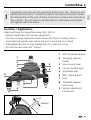
Function / Application
Alignment base for SuperPlane-Laser 3D / 3G Pro
– Robust metal base with vernier adjustment
– The free-moving alignment socket allows the oor or ceiling cross to
be positioned exactly, even when the unit is mounted on a tripod.
– Adjustable feet and circular bubble level for optimum set-up
– For 3D line laser with 5/8“ thread
1
2
3
4
5
6
7
8
9
5/8“ threaded adapter
Threaded adapter
holder
Free-moving base
Circular bubble level
Adjustable feet
5/8“ tripod thread
Lock
Threaded adapter
lock screw
Vernier adjustment
mechanism
Release
Lock
EN
Completely read through the operating instructions, the „Warranty and
Additional Information“ booklet as well as the latest information under
the internet link at the end of these instructions. Follow the instructions
they contain. This document must be kept in a safe place and passed
on together with the device.
!

06
1.
2.
1.
2.
3.
3.
4.
5.
6.
SuperPlane-Laser 3D Pro
SuperPlane-Laser 3D Pro
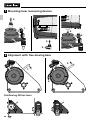
1Mounting laser measuring devices
2Alignment with free-moving base
Positioning 3D line laser
EN

CenterBase 2
07
SuperPlane-Laser 3D Pro
SuperPlane-Laser 3D Pro
SuperPlane-Laser 3D Pro
~72 mm
~40 mm
EN
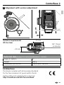
3Alignment with vernier adjustment
Technical data (Subject to technical alterations. 18W05)
Angle of rotation 3°
Weight 650 g
Dimensions (W x H x D) 120 x 150 x 140 mm
EU directives
This device complies with all necessary standards
for the free movement of goods within the EU.
Further safety and supplementary notices at:
http://laserliner.com/info?an=centbas2
Technical requirements
3D line laser
5/8" thread
(underside)

CenterBase 2
8.036.96.44.1 / Rev18W05
SERVICE
Umarex GmbH & Co. KG
– Laserliner –
Möhnestraße 149, 59755 Arnsberg, Germany
Tel.: +49 2932 638-300, Fax: +49 2932 638-333
info@laserliner.com
Umarex GmbH & Co. KG
Donnerfeld 2
59757 Arnsberg, Germany
Tel.: +49 2932 638-300, Fax: -333
www.laserliner.com
-
 1
1
-
 2
2
-
 3
3
-
 4
4
-
 5
5
-
 6
6
-
 7
7
-
 8
8


in anderen Sprachen
- English: Laserliner 036 31 User manual
Verwandte Artikel
-
Laserliner 031.213A Benutzerhandbuch
-
-
-
-
Laserliner AutoCross-Laser 3C Bedienungsanleitung
-
-
Laserliner PowerCross-Laser 5G Bedienungsanleitung
-
-
Laserliner PowerCross-Laser 8 S Bedienungsanleitung
-
Laserliner AL 32 Plus Benutzerhandbuch