Nakatanenga TEXU400 Benutzerhandbuch

Typ
Benutzerhandbuch
DE | 1
HANDBUCH | MANUAL V. 1
3
1. Sicherheitshinweise .......................................... 4
2. Technische Spezikationen .................................... 4
2.1 Absicherung der Stromkreise .................................. 5
2.1.1 Sicherungen ........................................... 6
2.1.2 Ausfallkontrollanzeige ................................... 7
2.2 Systemauslegung Kabelstärken ................................ 8
3. Negative Sammelschiene ...................................... 8
3.1 Shunt-Brücke ............................................... 8
4. Montage des TEXU400 ........................................ 9
5. Verkabelung ................................................. 9
tigerexped GmbH & Co. KG
Weseler Straße 82
46519 Alpen
Germany
+49(2845) 379 279-10
info@tigerexped.de
www.tigerexped.de
1. Safety Warnings ............................................ 10
2. Technical Specications ...................................... 11
2.1 Circuit Protection ........................................... 11
2.1.1 Fusing .............................................. 12
2.1.2 Blown Fuse Monitoring .................................. 12
2.2 System Conguration Wiring ................................. 14
3. Negative bus bar ............................................ 14
3.1 Shunt bridge .............................................. 14
4. Mounting the TEXU400 ....................................... 15
5. Wiring ..................................................... 15
WELCOME TO THE REVOLUTION
OF POWER DISTRIBUTION.
INHALT | CONTENT
DEUTSCH
ENGLISH
DE | 5 4 | DE
2.1 ABSICHERUNG DER STROMKREISE
Die positive Sammelschiene des TEXU400
verfügt über Anschlüsse von bis zu vier
Batterie-Bänken, sowie für bis zu 10 Hoch -
stromverbrauchern und vier Standard-
verbraucher. Alle Anschlüsse sind abgesichert,
verbraucherseitig ndet eine Ausfallkontrolle
mit Anzeige via LED-Beleuchtung statt, die
per Lichtleiter zum entsprechenden
Beschriftungsaufkleber auf der Abdeckung
geleitet wird.
Maximal zulässiger Gesamtstrom (Dauer):
400 A bei 35°C / 350 A bei 50°C.
Beachten Sie die Spezikationen in der
folgenden Tabelle:
1. SICHERHEITSHINWEISE
Das Arbeiten an elektrischen Anlagen
setzt Fachkenntnis voraus und sollte nur
von qualizierten Personen durchgeführt
werden. Bitte beachten Sie auch die
Batteriesicherheitshinweise, die in Ihrem
Batteriehandbuch aufgeführt sind.
2. TECHNISCHE SPEZIFIKATIONEN
Alle Angaben zu Kabelstärken in diesem
Dokument beziehen sich auf eine maximale
Umgebungstemperatur von 50°C. Wir
empfehlen dringend, die Verkabelung frei
und nicht innerhalb von Kabelkanälen zu
verlegen. Die angegebenen Kabelstärken und
deren maximale Strombelastung sind für freie
Verlegung ausgelegt.
Das TEXU400 ist ein DC-Hochstromverteiler
für bis zu 400 A Gesamtstrom. Integriert sind
positive und negative Sammelschienen zum
Anschluss von Batterien / Batteriebänken
und Verbrauchern, sowie werksseitig
installierter Shunt-Brücke auf der geteilten
negativ-Schiene zur optionalen Integration
einer Summenstrommessung oder / und
eines Hauptschalters. Alle Anschlüsse sind
abgesichert, verbraucherseitig ndet eine
Sicherungsausfallüberwachung statt.
TEXU400 ist nach ISO8846 gegenüber
brennbaren Gasen zündgeschützt.
Sicherungstyp max.
Kabelstärke max.
Strom Dauer max.
Strom kurz
MEGA-Sicherung
(Anschluss 1)
2× 70 mm2
(2× AWG 2/0) 250 A 300 A für max. 30 min
400 A für max. 5 min
MEGA-Sicherung
(Anschluss 2)
70 mm2
(AWG 2/0) 150 A 200 A für max. 30 min
300 A für max. 5 min
MIDI-Sicherungen
(Anschlüsse 3 bis 7)
70 mm2
(AWG 2/0) 150 A 170 A für 30 min
MIDI-Sicherungen
(Anschlüsse 8 bis 11)
50 mm2
(AWG 1/0) 120 A
ATO/ATP/ATC 25 A 30 A für max. 15 min
TECHNISCHE DATEN &
WICHTIGE INSTALLATIONSHINWEISE
Alle Angaben beziehen sich auf eine max. Umgebungstemperatur von 50° Celsius.
2
5
A
1
5
0
A
V
e
r
b
r
a
u
c
h
e
r
-
P
l
u
s
V
e
r
b
r
a
u
c
h
e
r
-
M
i
n
u
s
B
a
t
t
e
r
i
e
-
M
i
n
u
s
D
o
p
p
e
l
a
n
s
c
h
l
u
s
s
B
a
t
t
e
r
i
e
-
P
l
u
s
2
5
0
A
1
2
0
A
S
h
u
n
t
u
n
d
/
o
d
e
r
H
a
u
p
t
s
c
h
a
l
t
e
r
DE | 7 6 | DE
2.1.2 AUSFALLKONTROLLANZEIGE
Nutzen Sie zur Kennzeichnung der Strom-
kreise die im Lieferumfang enthaltenen
Aufkleber und platzieren Sie diese auf der
Frontabdeckung.
Die positive Sammelschiene des TEXU400
ist verbraucherseitig mit einer Sicherungs-
überwachungr jeden Stromkreis ausgestattet.
Beim Ausfall einer Sicherung wird das Licht
der anzeigenden LED per Lichtleiter zur Front-
abdeckung und der zugehörigen Beschriftung
geführt. Dies ermöglicht eine eindeutige,
einfache Diagnose, selbst bei geschlossener
Abdeckung.
Bitte beachten: Die Ausfallkontrolle zeigt nur
defekte Sicherungen von angeschlossenen
Verbrauchern an. Die Absicherung der
Batterien und etwaiger angeschlossener
Ladegeräte wird vom TEXU400 nicht angezeigt!
Achtung: Zur Umsetzung der Ausfall kontrolle,
wird absichtlich ein geringer Strom an
den Sicherungen vorbei zugelassen. Dieser
Strom kann in einigen Situationen sehr
kleine Verbraucher wie in Geräte eingebaute
LEDs oder sonstige LED-Spots leicht zum
Leuchten bringen, selbst wenn eine Sicherung
durchgebrannt oder entfernt ist! Da dieser
Strom auf etwa 1mA in 12V-Systemen bzw. bis
zu 5mA in 48V-Systemen begrenzt ist, stellt
dieses Phänomen kein Sicherheitsrisiko dar und
ist völlig normal.
2.1.1 SICHERUNGEN
Die positive Sammelschiene verfügt über
abgesicherte Anschlüsse für Batterie- und
Verbraucherseite.
Das TEXU400 hat Platz für insgesamt 15
Sicherungen, eine für jeden Gleichstromkreis.
Die Plätze sind für den Einbau von MEGA-,
MIDI / AMI-, sowie ATO / ATC / ATP Sicherungen
vorgesehen.
Verwenden Sie stets Sicherungen mit der
richtigen Spannung und Stromstärke.
Passen Sie die Sicherungsstärke an die
maximalen Spannungen und Ströme an, die im
gesicherten Stromkreis potenziell auftreten
können und bedenken Sie, dass die Belastung
mit der nominalen Amperezahl, nur eine
kurzfristige Absicherung zusst. Hierzu bitte
die Datenblätter des Sicherungsherstellers
konsultieren.
Verwenden Sie für 12 V- und 24 V-Systeme
Sicherungen mit 32/36 V und für 48 V-Systeme
Sicherungen mit 58 V.
MPPT
HOCHSTROM
INVERTER
OPTIONAL
B2B
BOOSTER
DE | 9 8 | DE
2.2 SYSTEMAUSLEGUNG KABELSTÄRKEN
Eine unterschiedliche Anzahl von Batterie-
nken und unterschiedliche Summenströme
erfordern eine differenzierte Auslegung des
Systems in Bezug auf die Kabelstärken.
Die Batterieeinspeisung erfolgt über maximal
4 Batteriebänke. Anschlüsse mit 3x 70 mm²
oder 4x 50 m.
Nachfolgend sind die empfohlenen Kabel stärken
tabellarisch aufgelistet. Alle Angaben beziehen
sich auf eine Umgebungstemperatur von
maximal 50° C.
Maximaler Summenstrom
1 5 0 A 200 A 3 0 0 A 4 0 0 A
Eine Batterie 70 mm2
(AWG 2/0) ---
Zwei Batterien 35 mm2
(AWG 2)
50 mm2
(AWG 1/0)
70 mm2
(AWG 2/0) -
Drei Batterien 25 mm2
(AWG 4)
35 mm2
(AWG 2)
50 mm2
(AWG 1/0)
70 mm2
(AWG 2/0)
Vier Batterien 16 mm2
(AWG 6)
25 mm2
(AWG 4)
35 mm2
(AWG 2)
50 mm2
(AWG 1/0)
3. NEGATIVE SAMMELSCHIENE
Auf der negativen Sammelscheine steht
jedem Anschluss auf der Plusseite ein eigener
Anschluss gegenüber. Die zu verwendenden
Kabelstärken entsprechen mit 70 mm² und
50 mm² ebenfalls ihrem jeweiligen Gegenüber.
r Kabelstärken ≤35 mm2 ist gegebenenfalls
eine Doppelbelegung der Anschlüsse
zulässig, sofern diese mechanisch sinnvoll zu
bewerkstelligen ist.
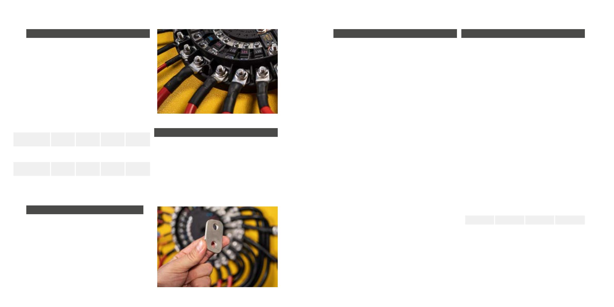
3.1 SHUNT-BRÜCKE
Die geteilte negative Sammelschiene ist
werksseitig über eine Shunt-Brücke verbunden.
Sie kann über zwei M10 Schraubanschsse
entfernt und durch den mitgelieferten
Isoliersteg zur Integration eines Mess-Shunts
und/oder eines Hauptschalters ersetzt werden.
Wird das TEXU400 mit der maximalen Strom-
stärke belastet, muss auf die Eignung des
hierfür verwendeten Kabels geachtet werden.
Entsprechendes Zubehör: tiger.jetzt/texu400
4. MONTAGE DES TEXU400
Zur Vermeidung von Korrosion, in einer vor
Feuchtigkeit geschützten Umgebung verbauen.
hlen Sie den Montageort möglichst nah an
den Batterien und Hochstromverbrauchern.
Nicht direkt über Bleisäure-Batterien mit
Entlüftung montieren, um das TEXU400
nicht korrodierenden Gasen auszusetzen.
Die Montage sollte auf einem nicht brennbaren
Untergrund erfolgen. Optional ist unter
tiger.jetzt/texu400 eine geeignete
Montageplatte zur Trennung erhältlich.
Das TEXU400 entspricht der Norm ISO8846. Es
ist somit gegenüber brennbaren Gasen zünd-
geschützt und für die Montage im Motorraum
zugelassen. Für die Einhaltung der Norm muss
die Frontabdeckung montiert und mit dem
Zentralknopf verriegelt sein, um eine Abdichtung
zwischen umlaufendem Steg der Basis und der
im Deckel liegenden Dichtung zu erreichen.
Unabhängig davon ist jedoch zu beachten, dass
die max. Umgebungs temperatur 50°C auf
keinen Fall überschreiten sollte und dass
jegliche Elektronik mit steigender Temperatur
hlprobleme und damit Leistungseinbußen
verzeichnen kann. Sofern möglich, sollte eine
Montage sämtlicher Elektrokomponenten (inkl.
des TEXU400) daher an gut belüfteten, eher
kühlen Orten erfolgen.
Zur Montage stehen im Basisteil des TEXU400
eine Zentrale und diverse radial angeordnete
Bohrungen für eine Verschraubung mit dem
Untergrund zur Verfügung. Beginnen Sie die
Montage mit der zentralen Schraube, um das
TEXU400 für die genauere Justage noch
bewegen zu können. Zum Anschluss der Kabel
sollen aufgrund auftretender Hebelkfte auch
die anderen Verschraubungspunkte fest-
gezogen sein, um mögliche Beschädigungen
der Grundplatte zu vermeiden.
5. VERKABELUNG
Bitte verwenden Sie ausschließlich
zugelassene Kabel mit fein adriger Litze
nach Automotive Standard FLYR oder FLY
(siehe unser Kabelsortiment unter
tiger.jetzt/kabel)
Aufgrund von Hitzeentwicklung ist
es ratsam, die Kabel von Hochstrom-
Sicherungsverteilern nicht in Kabelkanälen,
sondern frei zu verlegen.
Zum Anschluss der Kabel empfehlen wir
geschlossene, unisolierte Rohrkabelschuhe,
verzinnter Qualität.
Nach dem Crimpen mit einem geeigneten
Stück Schrumpfschlauch (passender
Durchmesser, ca. doppelt so lang wie
die zu bedeckende, gerade Stelle von
Kabelummantelung bis zur Biegung
des Rohrkabelschuhs) isolieren. Der
Schrumpfschlauch darf dabei nicht die
Kontaktächen bedecken!
Beachten Sie bei der Installation der Kabel
am TEXU400, die in der Basis eingeprägten
Drehmomente! Eine Verwendung eines
geeigneten Drehmomentschssels ist hier
unerlässlich!
Verbinden Sie die Pluskabel der Batterien
mit den Ports 3 - 6. Je nach Anzahl der
verwendeten Batterien, daran anschließend
die stärksten Verbraucher (ab Port 4 bei
Verwendung einer einzelnen Batterie).
Die Ports 8 - 11 sind für kleinere Verbraucher
mit MIDI-Absicherung vorgesehen.
Vorgeschriebene Anzugsmomente (Nm/ft-lb)
M4 M5 M8 M10
1,5/1,1 5,4/4 12,5/9,5 24,5 /18,1
EN | 1110 | EN
2.1 CIRCUIT PROTECTION
The positive bus bar of the TEXU400 integrates
connections for up to four battery banks, as
well as for up to 10 high-current and four
standard loads. Every single circuit is fuse-
protected.
Maximum permissible total current
(continuous): 400 A at 35°C / 95° F
and 350 A at 50°C / 122° F.
Note the specications in the following table:
1. SAFETY WARNINGS
Working on electrical systems requires
specialized knowledge and should only be
carried out by qualied personnel. Please also
observe the battery safety instructions listed
in your battery manual.
2. TECHNICAL SPECIFICATIONS
All information on wiring gauges in this
document relates to a maximum ambient
temperature of 50° Celsius / 122° Fahrenheit.
We therefore strongly recommend not to route
any cables within cable ducts. The specied
wiring gauges and their maximum current load
refer to open routing of all cables
The TEXU400 is a high-current DC distributor
for a total of 400 A. Positive and negative
bus bars for connecting batteries / battery
banks and loads are integrated, as well as
a pre-mounted shunt bridge on a divided
negative bus bar for the optional integration
of a current measurement device (such as a
shunt) and / or a main switch. All individual
circuits are protected by means of different
fuses (not included!). Blown fuse monitoring is
implemented for all connected loads.
TEXU400 is ignition-protected against
ammable gases in accordance with ISO8846.
Type of fuse max.
cable gauge
max.
continuous
current
max.
current intermittent
MEGA-Fuse
(Port 1)
2× AWG 2/0
(70 mm2)250 A 300 A / max. 30 min
400 A / max. 5 min
MEGA-Fuse
(Port 2)
AWG 2/0
(70 mm2)150 A 200 A / max. 30 min
300 A / max. 5 min
MIDI-Fuses
(Ports 3 bis 7)
AWG 2/0
(70 mm2)150 A 170 A / 30 min
MIDI-Fuses
(Ports 8 bis 11)
AWG 1/0
(50 mm2)120 A
ATO/ATP/ATC 25 A 30 A / max. 15 min
TECHNICAL SPECIFICATIONS &
IMPORTANT INSTALLATION INSTRUCTIONS
All data given at a maximum ambient temperature of 50° Celsius / 122° Fahrenheit.
2
5
A
1
5
0
A
l
o
a
d
p
o
s
i
t
i
v
e
s
d
u
a
l
t
e
r
m
i
n
a
l
c
o
n
n
e
c
t
i
o
n
b
a
t
t
e
r
y
i
n
p
u
t
s
2
5
0
A
1
2
0
A
s
h
u
n
t
a
n
d
/
o
r
m
a
i
n
s
w
i
t
c
h
b
a
t
t
e
r
y
g
r
o
u
n
d
s
l
o
a
d
g
r
o
u
n
d
s
EN | 1312 | EN
2.1.1 FUSING
On the positive bus bar there are fused ports to
connect batteries as well as loads.
The TEXU400 holds space for a total of 15
fuses, one for each DC circuit. The spaces are
suitable for the installation of MEGA, MIDI /
AMI and ATO / ATC / ATP fuses.
Always use fuses of correct voltage and
amperage. Adjust the fuse ratings to the
maximum voltages and currents that can
potentially occur in the protected circuit,
and remember that the load with the nominal
amperage only allows short-term protection.
Please refer to the data sheets of the fuse
manufacturer and or the device in question
regarding this.
Use fuses with 32V for 12V and 24V systems
and fuses with 58V for 48V systems.
2.1.2 BLOWN FUSE MONITORING
Use the stickers included with the TEXU400
to identify the circuits and place them on the
front cover.
The positive bus bar of the TEXU400 is
equipped with fuse monitoring for each
circuit. For connected loads, a blown fuse
detection circuit shows tripped fuses via LED
lighting, where the light is being routed
through special light guides to the corresponding
label on the cover to safely match the fuse in
question and the corresponding label for easy
identication even when the cover is closed.
Please note: The blown fuse monitoring only
shows defective fuses for connected loads.
The fusing of the batteries and any connected
chargers is not indicated by the TEXU400!
Note: To enable the feature of blown fuse
indication we intentionally allow a residual
current parallel to the fuse. This current can
potentially dimly light up very low power devices
such as single LEDs within appliances or LED
spots of all sorts even when fuse is blown or
totally removed! Since this current is limited to
around 1mA in 12V systems and around 5mA
in 48V systems, this phenomenon does not pose
any risk and is perfectly normal behavior.
HIGH POWER
INVERTER
MPPT
OPTIONAL
B2B
BOOSTER
EN | 1514 | EN
2.2 BATTERY INPUT WIRING
A different number of battery banks and
varying total currents require distinctive
congurations of the system with regard to the
wiring diameters.
The positive supply is fed in via a maximum
of 4 battery banks. Connections for max.
current re possible with 3x AWG 2/0 (70 mm²)
or 4x AWG 1/0 50 mm².
The recommended wiring gauges are listed in
the table below. Again, all data shown relates
to an ambient temperature of maximum 50°C /
122° Fahrenheit.
Maximum Permissible Continuous
Current
1 5 0 A 2 0 0 A 3 0 0 A 4 0 0 A
one battery AWG 2/0
(70 mm2)---
two batteries AWG 2
(35 mm2)
AWG 1/0
(50 mm2)
AWG 2/0
(70 mm2)-
three batteries AWG 4
(25 mm2)
AWG 2
(35 mm2)
AWG 1/0
(50 mm2)
AWG 2/0
(70 mm2)
four batteries AWG 6
(16 mm2)
AWG 4
(25 mm2)
AWG 2
(35 mm2)
AWG 1/0
(50 mm2)
bolt torque ratings (Nm/ft-lb)
M4 M5 M8 M10
1.5/1.1 5.4/4 12.5/9.5 24.5 /18.1
3. NEGATIVE BUS BAR
Each port on the positive bus bar has a
corresponding bolt on the negative bus bar.
The maximum wiring diameter to be used on
the negative bus bar also corresponds to their
respective counterparts in the positive side -
AWG 2/0 (70 mm2) and AWG 1/0 (50 mm2). For
diameters AWG 2 (35 mm2), two cable lugs on
a single bolt is permissible if needed, provided
that this can be achieved in a mechanically
sensible manner.
3.1 SHUNT BRIDGE
The split negative bus bar is equipped with a
pre-mounted shunt bridge. It can be removed
via the two 3/8“ (M10) bolt connections and
replaced by the supplied insulating divider for
integrating a current measuring shunt and / or
a main switch.
If the TEXU400 is to be used up to its rated
current maximum of 400 A, the suitability of
the cable used for connection of shunt and
main switch must be ensured. If necessary,
please order our special non-insulated ground
cable to achieve a safe and secure connection:
tiger.jetzt/texu400
4. MOUNTING THE TEXU400
Install in an environment protected from
moisture to avoid corrosion.
Choose the mounting location as close as
possible to the batteries and high-current
loads such as big inverters, winches or alike.
Do not mount directly above lead-acid
batteries with ventilation in order to not
expose the TEXU400 to corrosive gases.
The installation should take place on a non-
ammable surface. Optionally, you can get
a suitable mounting plate for separation:
tiger.jetzt/texu400
The TEXU400 complies with the ISO8846
standard. Therefore, it is ignition-protected
against ammable gases and approved for
mounting in the engine compartment. To
comply with the standard, the front cover
must be in place and securely locked with
the central knob in order to achieve a tight
seal between base and cover. Regardless of
this, it should be noted that the maximum
ambient temperature should not exceed
50° C / 12F under any circumstances and
that any electronics can experience cooling
problems and thus performance losses as the
temperature rises. If possible, all electrical
components (including the TEXU400) should
be installed in well-ventilated, rather cool
locations.
For mounting on the surface, there is one
central and various radially arranged boltholes
available in the base of the TEXU400. Start the
assembly with the central screw in order to be
able to rotate the TEXU400 for a more precise
alignment of ports and cables. To connect the
wiring, all other bolts holes must also be used
to avoid possible damage to the baseplate.
5. WIRING
Please only use approved cables with
ne-wire stranded wire, such as automotive
standard FLYR or FLY (see our cable range
at tiger.jetzt/cable). Check regulations
regarding cable choice for your application!
Due to heat development, it is advisable not
to lay cables of high-current distributors
in cable ducts. Please run them openly and
securely fastened.
To connect the wiring, we recommend
closed, uninsulated tubular cable lugs of
tinned quality.
After crimping, insulate with a suitable piece
of shrink tubing (suitable diameter, approx.
twice as long as the straight section of the
cable sheathing to be covered up to the bend
in the tubular cable lug). The shrink tubing
must not cover the contact surfaces!
When installing the cables on the TEXU400,
note the torques stamped on the baseplate.
The use of a suitable torque wrench is
essential here.
Connect the positive lines of the batteries
to ports 3 - 6. Depending on the number
of batteries used, the most powerful loads
should follow directly (from port 4 when
using a single battery). Ports 8 - 11 are
intended for smaller consumers with MIDI
fusing.
16 | DE
tiger.jetzt/texu400
tigerexped GmbH & Co. KG
Weseler Straße 82
46519 Alpen
Germany
+49(2845) 379 279-10
info@tigerexped.de
www.tigerexped.de
  • Page 1 1
  • Page 2 2
  • Page 3 3
  • Page 4 4
  • Page 5 5
  • Page 6 6
  • Page 7 7
  • Page 8 8
  • Page 9 9

Nakatanenga TEXU400 Benutzerhandbuch

Typ
Benutzerhandbuch

in anderen Sprachen