LD Systems AMP 106 T Benutzerhandbuch
- Kategorie
- Musikausrüstung
- Typ
- Benutzerhandbuch

USER´S MANUAL
BEDIENUNGSANLEITUNG
MANUEL D´UTILISATION
MANUAL DE USUARIO
INSTRUKCJA OBSŁUGI
MANUALE D´USO
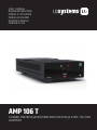
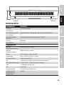
AMP 106 T
1-CHANNEL MINI INSTALLATION POWER AMPLIFIER 60 W @ 4 OHM / 70V / 100V
LDAMP106T

CONTENTS / INHALTSVERZEICHNIS / CONTENU / CONTENIDO / TREŚĆ / CONTENUTO
ENGLISH
ABOUT THIS MANUAL 3
INTENDED USE 3
EXPLANATIONS OF TERMS AND SYMBOLS 3
SAFETY INSTRUCTIONS 4
PACKAGING CONTENT 7
INTRODUCTION 7
CONNECTIONS, OPERATING AND
DISPLAY ELEMENTS 8
TERMINAL BLOCK CONNECTIONS 10
CONNECTION EXAMPLE 11
UNDER / ON-TABLE MOUNTING 12
CARE, MAINTENANCE AND REPAIR 13
DIMENSIONS 14
TECHNICAL DATA 14
DISPOSAL 16
MANUFACTURER´S DECLARATIONS 17
DEUTSCH
INFORMATIONEN ZU DIESER
BEDIENUNGSANLEITUNG 18
BESTIMMUNGSGEMÄSSER GEBRAUCH 18
BEGRIFFS- UND SYMBOLERKLÄRUNGEN 18
SICHERHEITSHINWEISE 19
LIEFERUMFANG 22
EINLEITUNG 22
ANSCHLÜSSE, BEDIENUNG UND
ANZEIGEELEMENTE 23
KLEMMLEISTENANSCHLÜSSE 25
ANSCHLUSSBEISPIEL 26
UNTER- / AUFTISCHMONTAGE 27
PFLEGE, WARTUNG UND REPARATUR 28
ABMESSUNGEN 29
TECHNISCHE DATEN 29
ENTSORGUNG 31
HERSTELLERERKLÄRUNGEN 32
FRANCAIS
INFORMATIONS SUR CE MODE D‘EMPLOI 33
UTILISATION RÉGLEMENTÉE 33
EXPLICATIONS DES TERMES ET DES SYMBOLES 33
CONSIGNES DE SÉCURITÉ 34
CONTENU DE L‘EMBALLAGE 37
INTRODUCTION 38
BRANCHEMENTS, UTILISATION ET INDICATEURS 39
CONNEXIONS EUROBLOCK (BORNIER) 41
EXEMPLE DE CONNEXION 42
MONTAGE SOUS / SUR TABLE 43
ENTRETIEN, MAINTENANCE ET RÉPARATIONS 44
DIMENSIONS 45
CARACTÉRISTIQUES TECHNIQUES 46
MISE EN DÉCHETTERIE 48
DÉCLARATIONS DU FABRICANT 49
ESPAÑOL
INFORMACIÓN SOBRE ESTAS
INSTRUCCIONES DE USO 50
USO CONFORME A LA NORMATIVA 50
EXPLICACIONES DE TÉRMINOS Y SíMBOLOS 50
INSTRUCCIONES DE SEGURIDAD 51
CONTENIDO DEL EMBALAJE 54
INTRODUCCIÓN 54
CONEXIONES, MANDOS E INDICADORES 55
CONEXIONES DEL BLOQUE DE TERMINALES 57
EJEMPLO DE CONEXIÓN 58
MONTAJE BAJO/SOBRE LA MESA 59
CUIDADO, MANTENIMIENTO Y REPARACIÓN 60
DIMENSIONES 61
DATOS TÉCNICOS 62
DISPOSICIÓN 64
DECLARACIONES DEL FABRICANTE 65

POLSKI
INFORMACJE DOTYCZĄCE NINIEJSZEJ
INSTRUKCJI OBSŁUGI 66
STOSOWANIE ZGODNIE Z PRZEPISAMI 66
OBJAŚNIENIA TERMINÓW I SYMBOLI 66
INSTRUKCJE BEZPIECZEŃSTWA 67
ZAWARTOŚĆ OPAKOWANIA 70
WPROWADZENIE 70
PRZYŁĄCZA, ELEMENTY OBSŁUGI I WSKAŹNIKI 71
POŁĄCZENIA TERMINALI ZACISKOWYCH 73
PRZYKŁAD POŁĄCZENIA 74
MONTAŻ POD / NA BLACIE 75
PIELĘGNACJA, KONSERWACJA I NAPRAWA 76
WYMIARY 77
DANE TECHNICZNE 78
DYSPOZYCJA 80
OŚWIADCZENIA PRODUCENTA 81
ITALIANO
INFORMAZIONI SU QUESTE ISTRUZIONI
PER L‘USO 82
UTILIZZO IN CONFORMITÀ ALLE NORMATIVE 82
SPIEGAZIONI DI TERMINI E SIMBOLI 82
ISTRUZIONI DI SICUREZZA 83
CONTENUTO DELL‘IMBALLAGGIO 86
INTRODUZIONE 86
CONNESSIONI, ELEMENTI DI COMANDO E
DI VISUALIZZAZIONE 87
COLLEGAMENTI DELLA MORSETTIERA 89
ESEMPIO DI CONNESSIONE 90
MONTAGGIO SOTTO/SU TAVOLO 91
CURA, MANUTENZIONE E RIPARAZIONE 92
INGOMBRO 93
DATI TECNICI 94
MALTIMENTO 96
DICHIARAZIONI DEL PRODUTTORE 97

4
ENGLISH
YOU HAVE MADE THE RIGHT CHOICE!
We have designed this product to operate reliably over many years. LD Systems stands for this
with its name and many years of experience as a manufacturer of high-quality audio products.
Please read this User‘s Manual carefully, so that you can begin making optimum use of your
LD Systems product quickly. You can find more information about LD SYSTEMS at our Internet
site WWW.LD-SYSTEMS.COM
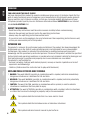
ABOUT THIS MANUAL
• Read the safety instructions and the entire manual carefully before commissioning.
• Observe the warnings on the unit and in the operating instructions.
• Always keep the operating instructions within reach.
• If you sell or pass on the appliance, be sure to hand over these operating instructions as well,
as they are an essential part of the product.
INTENDED USE
The product is a device for professional audio installation! The product has been developed for
professional use in the field of audio installation and is not intended for use in households!
Furthermore, this product is intended for installation by qualified persons with specialist
knowledge and for operation by instructed persons! The use of the product outside the specified
technical data and operating conditions is considered as not intended! Liability for damages and
third party damages to persons and property due to non-intended use is excluded!
The product is not suitable for:
• Persons (including children) with limited physical, sensory or mental capabilities or lack of
experience and knowledge.
• Children (children must be instructed not to play with the device)
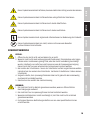
EXPLANATIONS OF TERMS AND SYMBOLS
1. DANGER: The word DANGER, possibly in combination with a symbol, indicates immediately
dangerous situations or conditions for life and limb.
2. WARNING: The word WARNING, possibly in combination with a symbol, indicates potentially
dangerous situations or conditions for life and limb.
3. CAUTION: The word CAUTION, possibly in combination with a symbol, is used to indicate
situations or conditions that may lead to injury.
4. ATTENTION: The word ATTENTION, possibly in combination with a symbol, refers to situations
or states that can lead to damage to property and/or the environment.
This symbol identifies hazards that can cause electric shock.
This symbol identifies hazardous areas or hazardous situations.
This symbol indicates hazards caused by hot surfaces.
ITALIANO
POLSKI
ESPAÑOL
FRANCAIS
DEUTSCHENGLISH

5
This symbol indicates dangers due to high volume levels.
This symbol denotes a device that does not contain any user-serviceable parts.
This symbol indicates additional information on the operation of the product.
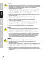
SAFETY INSTRUCTIONS
DANGER:
1. Do not open the device and do not perform any modifications.
2. If your device no longer functions properly, if liquids or objects get inside it or if it
has been damaged in any other way, switch it off immediately and disconnect it
from the mains. The device may be repaired only by authorised repair technicians.
3. For devices of protection class 1, the protective conductor must be connected
correctly. Never disconnect the protective conductor. Devices of protection
class 2 do not have a protective conductor.
4. Ensure that live cables are not kinked or otherwise mechanically damaged.
5. Never bypass the device fuse.
WARNING:
1. The device may not be operated if it shows obvious signs of damage.
2. The device may only be installed in a voltage-free state.
3. If the mains cable of the device is damaged, do not operate the device.
4. Permanently connected power cables may only be replaced by a qualified person.
CAUTION:
1. Do not operate the device if it has been exposed to strong temperature fluctuations
(for example, after transport). Moisture and condensate could damage the device.
Do not switch on the device until it has reached ambient temperature.
2. Make sure that the voltage and frequency of the mains supply match the values
indicated on the device. If the device has a voltage selector switch, do not connect
the device until it is set correctly. Use only suitable power cords.
3.
To completely disconnect the device from the power supply, unplug the power cable or
power adapter from the outlet. It is not sufficient to press the on/off switch on the unit.
4. Only replace the fuse with a fuse of the same type and rating indicated on the device.
5. Make sure that suitable measures have been taken against overvoltage
(e.g. lightning strike).
6. Observe the specified maximum output current on devices with Power Out
connection. Ensure that the total current consumption of all connected devices
does not exceed the specified value.
7. Replace pluggable mains cables only with original cables.
DEUTSCHFRANCAIS
ESPAÑOL ENGLISH
ITALIANO POLSKI

6
DANGER:
1. Choking hazard! Plastic bags and small parts must be kept out of reach of persons
(including children) with reduced physical, sensory or mental capabilities.
2. Danger of falling down! Make sure that the device is securely installed and cannot
fall down. Only use suitable stands or mountings (especially for fixed installations).
Make sure that accessories are properly installed and secured. Make sure that
applicable safety regulations are observed.
WARNING:
1. Use the device only in the manner intended.
2. Operate the device only with the accessories recommended and intended by the
manufacturer.
3. During installation, observe the safety regulations applicable in your country.
4. After connecting the device, check all cable routes to prevent damage or accidents,
e.g. due to tripping hazards.
5. It is essential to observe the specified minimum distance to normally flammable
materials! If this is not explicitly stated, the minimum distance is 0.3 m.
CAUTION:
1. In the case of moving components such as mounting brackets or other moving
components, there is a possibility of jamming.
2. In the case of units with motor-driven components, there is a risk of injury from the
movement of the unit. Sudden device movement can cause shockreactions.
CAUTION:
1. Do not install or operate the unit near any radiators, heat registers, stoves, or other
sources of heat. Always ensure that the device is installed in such a way that it is
sufficiently cooled and cannot overheat.
2. Do not place ignition sources such as lighted candles near the unit.
3. Ventilation openings must not be covered and fans must not be blocked.
4.
Use the original packaging or packaging provided by the manufacturer for transport.
5. Avoid shocks or impacts to the device.
6. Observe the IP protection class as well as the ambient conditions such as
temperature and humidity according to the specification.
7. Devices may be subject to continuous development. In case of deviating
information on operating conditions, performance or other device characteristics
between operating instructions and device labeling, the information on the device
always has priority.
8. The device is not suitable for tropical climates and for operation above 2000 m
above sea level.
9.
Unless explicitly stated, the device is not suitable for operation under marine conditions.
ITALIANO
POLSKI
ESPAÑOL
FRANCAIS
DEUTSCHENGLISH

7
NOTICE:
In the case of conversion or retrofit kits or accessories provided by the manufacturer,
be sure to follow the enclosed instructions.
CAUTION HIGH VOLUME AUDIO PRODUCTS!
This device is intended for professional use. Commercial operation of this device is
subject to applicable national regulations and guidelines for accident prevention.
Hearing Damage from High Volume and Continuous Exposure: Use of this product
may generate high sound pressure levels (SPL) that can cause hearing damage.
Avoid exposure to high volume levels.
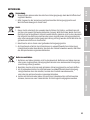
NOTES FOR INDOOR INSTALLATION EQUIPMENT
1. Units for installation applications are designed for continuous operation.
2. Units for indoor installation are not weatherproof.
3. Surfaces and plastic parts of installation equipment can also age, e.g. due to UV
radiation and temperature fluctuations.
This does not usually lead to functional restrictions.
4. with permanently installed units, the deposition of impurities, e.g. dust, is to be
expected. Be sure to observe the care instructions.
5. Unless explicitly stated otherwise on the unit, the units are intended for
installation heights of less than 5 m.
PACKAGING CONTENT
Remove the product from the packaging and remove all packaging material.
Please check the completeness and integrity of the delivery and notify your distribution
partner immediately after purchase if the delivery is not complete or if it is damaged.
The packaging includes:
• 1 x AMP 106 T installation amplifier
• 1 x power supply unit
• 1 set of terminal blocks
• 1 x mounting set for under- or on-table mounting
• User manual
INTRODUCTION
The AMP 106 T is a 1-channel mini installation amplifier from the TICA® series and is ideal for use
in sound installations where small dimensions, passive cooling and high efficiency are required.
The highly efficient 60W Class-D amplifier, with Lo-Z / Hi-Z selector switch and 4 Ohm / 100V / 70V
outputs, is convection-cooled and a straightforward solution for professional installers.
With a size of 1/4 19“ rack, 1U, the mini AMP 106 T fits perfectly in any installation location.
The supplied mounting plates offer maximum flexibility and facilitate discreet mounting,
whether on the table or on the wall. Installation in suspended ceilings is also no problem
thanks to the compact size and passive cooling.
DEUTSCHFRANCAIS
ESPAÑOL ENGLISH
ITALIANO POLSKI

8
For space-saving installation in the rack, an optional rack tray offers you the possibility to place
up to four products of the TICA® series next to each other.
Terminal strip connections on the balanced line inputs and speaker outputs make wiring
particularly easy.
Thanks to the option of remote control through third-party devices, you can conveniently adjust
the volume or put the power amplifier into standby mode at any time, even when it‘s hidden.
The perfect solution for professional installers and users looking for a compact, highly efficient
and easy-to-integrate solution.
FEATURES
• Professional mini amplifier
• 60W Class-D amplifier with Lo-Z / Hi-Z selector switch and 4 Ohm / 100V / 70V outputs
• Small form factor 1/4 19" rack, 1U
• Silent operation due to passive cooling
• Third-party connectivity for remote standby and volume control
• External wide-range switch mode power supply
• Incl. mounting plates for inconspicuous audio installations
• Suitable for fixed installation in suspended ceilings
• Balanced line input and speaker output with terminal strips
• User-friendly front panel with signal, clip and protection LEDs
• Optional rack tray for combination with other products of the TICA® series
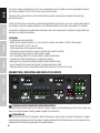
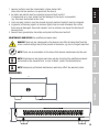
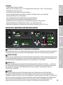
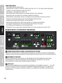
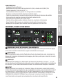
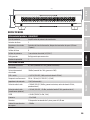
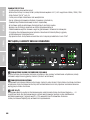
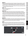
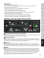
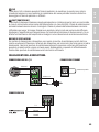
CONNECTIONS, OPERATING AND DISPLAY ELEMENTS
45
63
8
7
2
1
1 TERMINAL BLOCK CONNECTION FOR POWER SUPPLY
Terminal block connection for the device‘s power supply. To avoid damage to the unit, please use
only the original power supply (power supply unit included).
2 STRAIN RELIEF
Use the strain relief for the flexible cable of the power supply unit to protect the device‘s power
terminal block connector and the power supply terminal block from damage and to prevent the
terminal block from being pulled out unintentionally.
ITALIANO
POLSKI
ESPAÑOL
FRANCAIS
DEUTSCHENGLISH

9
3 LINE IN L/R
Analogue audio inputs with balanced terminal block connections. The +, - and G poles are for the
balanced input signal (suitable for unbalanced cabling). The signals of the inputs L and R are
internally mono summed. Terminal blocks are included in the packaging content.
4 OUTPUT
The loudspeaker output with terminal block connection (terminal block included in the packaging
content) enables the use of low-impedance loudspeakers with an impedance of at least 4 ohms
(switch LO-Z/HI-Z in position LO-Z) as well as 70 V or 100 V loudspeakers (switch LO-Z/HI-Z in
position HI-Z). Please observe the correct assignment of the terminal block poles (see TERMINAL
BLOCK CONNECTIONS in this manual). The total power handling of the connected speakers should
be approximately equal to the amplifier power.
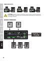
5 HI-Z / LO-Z
Before operating the unit, make sure that the switch is in the correct position!
Low impedance loudspeakers: LO-Z
70 V and 100 V loudspeakers: HI-Z
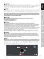
6 SETTINGS
DIP switch 1 STANDBY: Move the switch to the ON position to activate the automatic
standby function of the unit. If the standby function is activated, the amplifier is automatically
set to standby mode if no audio signal is detected for about 20 minutes. This reduces power
consumption in a sensible way. As soon as an audio signal is present, the amplifier is
automatically booted up from standby mode and is fully operational again within approximately
3 seconds. The power symbol on the front panel lights up red in standby mode. If the power
symbol lights up white, the unit is ready for operation.
DIP switch 2 HPF: Move the switch to ON position to activate the high-pass filter (HPF 110 Hz).
7 STANDBY
Standby mode can be activated manually with the help of an external button (momentary
switch). Press the button to activate standby mode and mute the speaker outputs. Press the
button again to end standby mode. The standby function via external button has priority over
the automatic standby function (see SETTINGS).
8 VCA
Terminal block connector for the use of an external volume control. The maximum volume is set
on the VOLUME control on the front panel. Once you have set the maximum volume, you can use
the external volume control to adjust the volume of the unit from the minimum value to the
preset value as desired. Please observe the correct assignment of the terminal block poles
(see TERMINAL BLOCK CONNECTIONS in this manual).
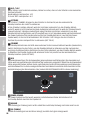
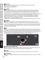
11 12
10
13 9
DEUTSCHFRANCAIS
ESPAÑOL ENGLISH
ITALIANO POLSKI

10
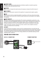
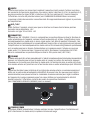
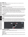
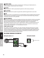
9 POWER SYMBOL
The power symbol lights up white when the installation amplifier is ready for operation.
In standby mode, the symbol lights up red.
10 VOLUME
Volume control. Turning to the right increases the volume, turning to the left decreases it.
11 SIG (SIGNAL)
As soon as an audio signal is present at the amplifier, the signal indicator lights up white.
12 CLIP
The CLIP indicator lights up when the amplifier is overdriven. In this case, reduce the volume
level. Failure to do so may result in distorted sound reproduction and damage to the amplifier
and speakers.
13 PROT (PROTECT)
The Protect indicator lights up permanently if the system is overloaded or overheats, in case
of a short circuit in the loudspeaker path and in case of a defect. The amplifier is automatically
muted. Disconnect the amplifier from the power supply and let it cool down for some time.
Eliminate a possible short circuit in the speaker path. Reconnect the amplifier to the power
supply. If the Protect indicator still lights up, there is a defect in the amplifier electronics.
Contact an authorised service workshop.
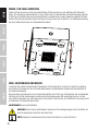
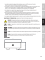
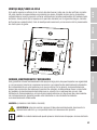
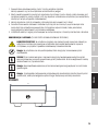
AIR VENTS
To prevent damage to the device, do not cover the ventilation openings on the left and right
sides and on the top and bottom of the device and ensure that air can circulate freely. Covering
the ventilation openings on the top or bottom of the enclosure when mounting it underneath
or on top of a table is not critical, as the cooling provided by the ventilation openings on the
remaining sides is sufficient.
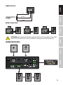
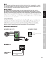
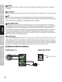
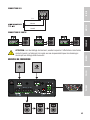
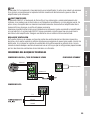
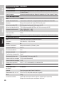
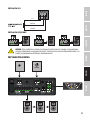
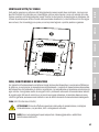
TERMINAL BLOCK CONNECTIONS
LINE IN L / R CONNECTIONS STANDBY CONNECTIONS
balanced
unbalanced
momentary switch
ITALIANO
POLSKI
ESPAÑOL
FRANCAIS
DEUTSCHENGLISH

11
CONNECTIONS VCA
Ground
5 V
Volume
OUTPUT CONNECTIONS
ATTENTION:
When wiring terminal blocks, please note the correct assignment of the poles/
terminals. The manufacturer accepts no liability for damage caused by faulty wiring!
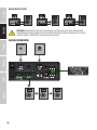
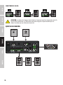
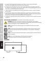
CONNECTION EXAMPLE
ON
1 2
VOLUME
ON/STANDBY
DEUTSCHFRANCAIS
ESPAÑOL ENGLISH
ITALIANO POLSKI

12
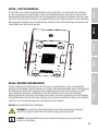
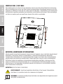
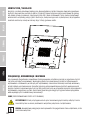
UNDER / ON-TABLE MOUNTING
There are two recesses on the top and bottom of the enclosure, each with two M3 threaded
holes, for mounting underneath or on top of the table. Screw the two enclosed mounting plates
to the top or bottom side using the enclosed M3 countersunk screws. Now the amplifier can be
fixed in the desired position (see illustration, fixing screws not included). For tabletop mounting,
the four rubber feet must be removed beforehand.
Art No. XXX
PRODUCTNAME
GEZEICHNET
GEPRÜFT
GENEHMIGT
PRODUKTION
QUALITÄT
WENN NICHT ANDERS DEFINIERT:
BEMASSUNGEN SIND IN MILLIMETER
OBERFLÄCHENBESCHAFFENHEIT:
TOLERANZEN:
LINEAR:
WINKEL:
OBERFLÄCHENGÜTE:
NAME
SIGNATUR
DATUM
WERKSTOFF:
GEWICHT:
A2
BLATT 1 VON 2
MASSSTAB:1:1
ZEICHNUNGSNR.
BENENNUNG:
ÄNDERUNG
ZEICHNUNG NICHT SKALIEREN
ENTGRATEN
UND SCHARFE
KANTEN
BRECHEN
CARE, MAINTENANCE AND REPAIR
To ensure the proper functioning of the device in the long term, it must be cared for regularly
and serviced as required. The care and maintenance requirements depend on the intensity of
use and environment.
We generally recommend a visual inspection before each start-up. Furthermore, we recommend
carrying out all the maintenance measures listed below every 500 operating hours or, in the
case of less intensive use, after one year at the latest. Defects due to insufficient care may result
in limitations of the warranty claims.
MAINTENANCE (user performable)
WARNING! Prior to any maintenance measures, the voltage supply and, if possible, all
device connections must be disconnected.
NOTE! Improper maintenance may impair the device or even destroy it.
ITALIANO
POLSKI
ESPAÑOL
FRANCAIS
DEUTSCHENGLISH

13
1. Housing surfaces must be cleaned with a clean, damp cloth.
Make sure that no moisture can penetrate the device.
2. Air inlets and outlets must be regularly cleaned of dust and dirt.
If compressed air is used, make sure that damage to the device is prevented
(e.g. fans must be blocked in this case).
3. Lines and plug contacts must be cleaned regularly and dust and dirt must be removed.
4. In general, no cleaning agents or abrasive agents may be used, otherwise the surface
finish may be damaged. Especially solvents, such as alcohol, can impair the function of
housing seals.
5. Devices must generally be stored dry and protected from dust and dirt.
MAINTENANCE AND REPAIR (by qualified personnel only)
DANGER! There are live components in the device. Even after disconnection from the
mains, residual voltage may still be present in the device, e.g. due to charged capacitors.
NOTE! There are no assemblies in the device that require maintenance by the user.
NOTE! Maintenance and repair work may only be carried out by qualified personnel
authorized by the manufacturer. In case of doubt, contact the manufacturer.
NOTE! Improperly performed maintenance work may affect the warranty claim.
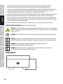
DIMENSIONS
LD Systems
®
is a registered brand of the Adam Hall Group.
Adam-Hall-Str. 1 · 61267 Neu-Anspach · Germany
DESIGNED AND ENGINEERED IN GERMANY. Assembled in PRC
106
53
43
221,7
Art No. XXX
PRODUCTNAME
GEZEICHNET
GEPRÜFT
GENEHMIGT
PRODUKTION
QUALITÄT
WENN NICHT ANDERS DEFINIERT:
BEMASSUNGEN SIND IN MILLIMETER
OBERFLÄCHENBESCHAFFENHEIT:
TOLERANZEN:
LINEAR:
WINKEL:
OBERFLÄCHENGÜTE:
NAME
SIGNATUR
DATUM
WERKSTOFF:
GEWICHT:
A2
BLATT 2 VON 2
MASSSTAB:1:1
ZEICHNUNGSNR.
BENENNUNG:
ÄNDERUNG
ZEICHNUNG NICHT SKALIEREN
ENTGRATEN
UND SCHARFE
KANTEN
BRECHEN
221,7
DEUTSCHFRANCAIS
ESPAÑOL ENGLISH
ITALIANO POLSKI

14
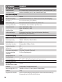
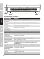
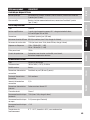
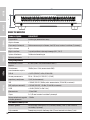
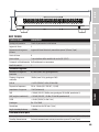
TECHNICAL DATA
Item number LDAMP106T
Product type Installation power amplifier
Line inputs 2
Line input connectors balanced line inputs, pitch 3.81 mm terminal block (3-pin)
Line outputs 0
Powered outputs 1 with output mode selector (LO-Z / HI-Z)
Cooling system Convection cooling
Priority levels 1
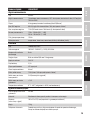
Input Section
Nominal input sensitivity 8.5 dBu (sine 1 kHz, gain max)
Nominal input clipping 18 dBu (sine 1 kHz, gain 0dB)
THD+N < 0.02% (SPK OUT, 4 dBu, 20 kHz BW)
Frequency response 20 Hz – 20 kHz (LO-Z SPK OUT, –0.5 dB)
Input impedance 12 kohms (balanced)
SNR > 100 dB (SPK OUT, 8 dBu, gain max, 20 kHz BW, A-weighted)
SNR (best conditions) > 102 dB (SPK OUT, +13 dBu, 22 kHz BW, A-weighted)
CMRR > 48 dB (SPK OUT, 4 dBu 1 kHz)
Gain –33 to 18 dB
Connector 2 x 3.81 mm terminal block 3-pin
Standby wake up threshold –30 dBu
3rd Party Control
Main volume 10k (linear taper) External potentiometer, pitch 3.5 mm terminal block (3-pin)
Power standby External momentary button, pitch 3.5 mm terminal block (2-pin)
Amplier output
Type Class D
Amplifier outputs 1-channel, mono summed, LO-Z: 4 ohm minimum load, HI-Z 70 V or 100 V outputs
Connector 4-pin terminal block (pitch 5.08 mm)
RMS output power 60 W (continuous sine wave 1 kHz, 4 ohm load)
Peak output power 72 W (100 msec sine 1 kHz burst @ 4 ohm load)
Frequency response 15 Hz – 20 kHz (LO-Z, –1 dB)
20 Hz – 20 kHz (HI-Z, –1 dB)
High pass filter 110 Hz
Protection Over/Undervoltage, Overtemperature, Short-Circuit, DC-Detection
ITALIANO
POLSKI
ESPAÑOL
FRANCAIS
DEUTSCHENGLISH

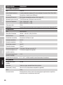
15
Item number LDAMP106T
Power Supply
Type External SMPS
Voltage range 100 VAC – 240 VAC (+–10%), 50 – 60 Hz
Mains fuse none
Secondary connector Terminal block 5.08 mm 2-pole
Secondary Voltage 24 V DC
Secondary Current 3,5 A
Primary connector IEC Jack
Safety class Class 1
Max power consumption 75 W (sine 1 kHz with 4 ohm load)
Idle power consumption 2 W (no signal input)
Standby power consuption < 1 W
Operating temperature 0°C – 40°C; < 85% humidity, non condensing
General
Time to standby 20 min.
Material Steel chassis, plastic front panel
Dimensions (w x h x d) 106 x 53 x 221.7 mm (height with rubber feet)
Weight 1.3 kg
Included accessories External power supply, mounting plates for surface mount applications,
terminal blocks for electrical connections.
DEUTSCHFRANCAIS
ESPAÑOL ENGLISH
ITALIANO POLSKI

16
DISPOSAL
Packaging:
1. Packaging can be disposed of via the usual waste disposal channels.
2. Please separate the packaging according to the waste disposal and materials
regulations in your country.
Device:
1. This device is subject to the European Directive on Waste Electrical and Electronic
Equipment in its applicable version. WEEE Directive- Waste Electrical and Electroni-
cal Equipment. Old devices and batteries do not belong in household waste. The old
device or batteries must be disposed of via an approved waste disposal service or a
municipal waste disposal facility. Follow the directives in your country!
2. Follow the disposal laws in your country.
3. As a private customer, you can obtain information on environmentally friendly
disposal options from the retailer from whom you purchased the product or from
the relevant regional authorities.
Batteries and rechargeable batteries:
1. Batteries and rechargeable batteries do not belong in household waste. Batteries
and rechargeable batteries must be disposed of via an authorised disposal company
or a municipal disposal facility.
2. Observe all disposal laws and regulations applicable in your country.
3. As a private customer, you can obtain information on environmentally friendly
disposal options from the dealer from whom the product was purchased or from
the relevant regional authorities.
4. Appliances with batteries or accumulators that cannot be removed by the user
must be handed in at a collection point for electrical appliances.
ITALIANO
POLSKI
ESPAÑOL
FRANCAIS
DEUTSCHENGLISH

17
MANUFACTURER´S DECLARATIONS
MANUFACTURER‘S WARRANTY & LIMITATIONS OF LIABILITY
Adam Hall GmbH, Adam-Hall-Str. 1, D-61267 Neu Anspach / E-mail [email protected] /
+49 (0)6081 / 9419-0.
Our current warranty conditions and limitation of liability can be found at:
https://cdn-shop.adamhall.com/media/pdf/MANUFACTURERS-DECLARATIONS_LD_SYSTEMS.pdf.
Contact your distribution partner for service.
UKCA-CONFORMITY
Hereby, Adam Hall Ltd. declares that this product meets the following guidelines (where applicable)
Electrical Equipment (Safety) Regulations 2016
Electromagnetic Compatibility Regulations 2016 (SI 2016/1091)
The Restriction of the Use of Certain Hazardous Substances in Electrical and Electronic Equipment
Regulation 2012 (SI 2012/3032)
Radio Equipment Regulations 201 7(SI 2016/2015)
UKCA-DECLARATION OF CONFORMITY
Products that are subject to Electrical Equipment(Safety)Regulation 2016, EMC Regulation 2016 or
RoHS Regulation can be requested at
[email protected]. Products that are subject to the Radio Equipments Regulations 2017
(SI2017/1206) can be downloaded from
www.adamhall.com/compliance/
CE CONFORMITY
Adam Hall GmbH hereby confirm that this product meets the following guidelines
(where applicable):
R&TTE (1999/5/EC) or RED (2014/53/EU) as of June 2017.
Low Voltage Directive (2014/35/EU)
EMC Directive (2014/30/EU)
RoHS (2011/65/EU)
The complete Declaration of Conformity can be found at www.adamhall.com.
Furthermore, you can also request it at [email protected].
CE DECLARATION OF CONFORMITY
Declarations of conformity for products subject to the LVD, EMC, RoHS Directive
can be requested from [email protected].
Declarations of conformity for products subject to RED Directive
can be downloaded from www.adamhall.com/compliance/.
Subject to misprints and errors, as well as technical or other modifications!
DEUTSCHFRANCAIS
ESPAÑOL ENGLISH
ITALIANO POLSKI

18
DEUTSCH
SIE HABEN DIE RICHTIGE WAHL GETROFFEN!
Wir haben dieses Produkt so konzipiert, dass es über viele Jahre hinweg zuverlässig funktioniert.
Dafür steht LD Systems mit seinem Namen und seiner langjährigen Erfahrung als Hersteller von
hochwertigen Audioprodukten. Bitte lesen Sie diese Bedienungsanleitung sorgfältig durch,
damit Sie Ihr LD SYSTEMS Produkt schnell optimal nutzen können. Weitere Informationen über
LD SYSTEMS finden Sie auf unserer Internet-Seite WWW.LD-SYSTEMS.COM
INFORMATIONEN ZU DIESER BEDIENUNGSANLEITUNG
• Lesen Sie vor Inbetriebnahme die Sicherheitshinweise und die gesamte Anleitung aufmerksam durch.
• Beachten Sie die Warnungen auf dem Gerät und in der Bedienungsanleitung.
• Bewahren Sie die Bedienungsanleitung immer in Reichweite auf.
• Wenn Sie das Gerät verkaufen oder weitergeben, händigen Sie unbedingt auch diese
Bedienungsanleitung aus, da sie ein wesentlicher Bestandteil des Produkts ist.
BESTIMMUNGSGEMÄSSER GEBRAUCH
Das Produkt ist ein Gerät für die professionelle Audioinstallation!
Das Produkt wurde für den professionellen Einsatz im Bereich der Audioinstallation entwickelt
und ist nicht für den Einsatz in Haushalten vorgesehen!
Außerdem ist dieses Produkt für die Installation durch qualifizierte Personen mit
Fachkenntnissen und für die Bedienung durch eingewiesene Personen bestimmt!
Die Benutzung des Produkts außerhalb der spezifizierten technischen Daten und
Betriebsbedingungen gilt als nicht bestimmungsgemäß!
Haftung für Schäden und Drittschäden an Personen und Sachen durch nicht
bestimmungsgemäßen Gebrauch ist ausgeschlossen!
Das Produkt ist nicht geeignet für:
• Personen (einschließlich Kinder) mit eingeschränkten körperlichen, sensorischen oder
geistigen Fähigkeiten oder mangelnder Erfahrung und Kenntnis.
• Kinder (Kinder müssen angewiesen werden, nicht mit dem Gerät zu spielen).
BEGRIFFS- UND SYMBOLERKLÄRUNGEN
1. GEFAHR: Mit dem Wort GEFAHR, evtl. in Kombination mit einem Symbol, wird auf
unmittelbar gefährliche Situationen oder Zustände für Leib und Leben hingewiesen.
2. WARNUNG: Mit dem Wort WARNUNG, evtl. in Kombination mit einem Symbol, wird auf
potentiell gefährliche Situationen oder Zustände für Leib und Leben hingewiesen.
3. VORSICHT: Mit dem Wort VORSICHT, evtl. in Kombination mit einem Symbol, wird auf
Situationen oder Zustände hingewiesen, die zu Verletzungen führen können.
4. ACHTUNG:
Mit dem Wort ACHTUNG, evtl. in Kombination mit einem Symbol, wird auf Situa tionen
oder Zustände hingewiesen, die zu Sach- und/oder Umweltschäden führen können.
ITALIANO
POLSKI
ESPAÑOL
FRANCAIS
DEUTSCHENGLISH

19
Dieses Symbol kennzeichnet Gefahren, die einen elektrischen Schlag verursachen können.
Dieses Symbol kennzeichnet Gefahrenstellen oder gefährliche Situationen.
Dieses Symbol kennzeichnet Gefahren durch heiße Oberflächen.
Dieses Symbol kennzeichnet Gefahren durch hohe Lautstärken.
Dieses Symbol kennzeichnet ergänzende Informationen zur Bedienung des Produkts.
Dieses Symbol kennzeichnet ein Gerät, in dem sich keine vom Benutzer
austauschbaren Teile befinden.
SICHERHEITSHINWEISE
GEFAHR:
1. Öffnen Sie das Gerät nicht und verändern Sie es nicht.
2. Wenn Ihr Gerät nicht mehr ordnungsgemäß funktioniert, Flüssigkeiten oder Gegen-
stände in das Geräteinnere gelangt sind, oder das Gerät anderweitig beschädigt
wurde, schalten Sie es sofort aus und trennen es von der Spannungsversorgung.
Dieses Gerät darf nur von autorisiertem Fachpersonal repariert werden.
3. Bei Geräten der Schutzklasse 1 muss der Schutzleiter korrekt angeschlossen werden.
Unterbrechen Sie niemals den Schutzleiter. Geräte der Schutzklasse 2 haben keinen
Schutzleiter.
4. Sorgen Sie dafür, dass spannungsführende Kabel nicht geknickt oder anderweitig
mechanisch beschädigt werden.
5. Überbrücken Sie niemals die Gerätesicherung.
WARNUNG:
1. Das Gerät darf nicht in Betrieb genommen werden, wenn es offensichtliche
Beschädigungen aufweist.
2. Das Gerät darf nur im spannungsfreien Zustand installiert werden.
3. Wenn das Netzkabel des Geräts beschädigt ist, darf das Gerät nicht in Betrieb
genommen werden.
4. Fest angeschlossene Netzleitungen dürfen nur von einer qualifizierten Person
ersetzt werden.
DEUTSCHFRANCAIS
ESPAÑOL ENGLISH
ITALIANO POLSKI

20
ACHTUNG:
1. Nehmen Sie das Gerät nicht in Betrieb, wenn es starken Temperaturschwankungen
ausgesetzt war (beispielsweise nach dem Transport). Feuchtigkeit und Kondensat
könnten das Gerät beschädigen. Schalten Sie das Gerät erst ein, wenn es
Umgebungstemperatur erreicht hat.
2. Stellen Sie sicher, dass die Spannung und die Frequenz des Stromnetzes mit den
auf dem Gerät angegebenen Werten übereinstimmen. Verfügt das Gerät über
einen Spannungswahlschalter, schließen Sie das Gerät erst an, wenn dieser
korrekt eingestellt ist. Nutzen Sie nur geeignete Netzkabel.
3. Um das Gerät allpolig vom Netz zu trennen genügt es nicht, den Ein-/Aus-Schalter
am Gerät zu betätigen.
4. Stellen Sie sicher, dass die eingesetzte Sicherung dem auf dem Gerät
abgedruckten Typ entspricht.
5. Stellen Sie sicher, dass geeignete Maßnahmen gegen Überspannung
(z.B. Blitzschlag) ergriffen wurden.
6. Beachten Sie den angegebenen maximalen Ausgangsstrom an Geräten mit
Power Out Anschluss. Beachten Sie, dass die gesamte Stromaufnahme aller
angeschlossenen Geräte den vorgegebenen Wert nicht überschreitet.
7. Ersetzen Sie steckbare Netzleitungen nur durch Originalleitungen.
GEFAHR:
1. Erstickungsgefahr! Kunststoffbeutel und Kleinteile müssen außer Reichweite
von Personen (einschließlich Kindern) mit eingeschränkten körperlichen,
sensorischen oder geistigen Fähigkeiten aufbewahrt werden.
2. Gefahr durch Herabfallen! Stellen Sie sicher, dass das Gerät sicher installiert ist
und nicht herunterfallen kann. Verwenden Sie ausschließlich geeignete Stative
bzw. Befestigungen (im Besonderen bei Festinstallationen). Stellen Sie sicher,
dass Zubehör ordnungsgemäß installiert und gesichert ist. Achten Sie dabei
darauf, dass geltende Sicherheitsbestimmungen eingehalten werden.
WARNUNG:
1. Verwenden Sie das Gerät nur in der vorgesehenen Art und Weise.
2. Betreiben Sie das Gerät nur mit dem vom Hersteller empfohlenen und
vorgesehenen Zubehör.
3. Beachten Sie bei der Installation die für Ihr Land geltenden Sicherheitsvorschriften.
4. Überprüfen Sie nach dem Anschluss des Geräts alle Kabelwege, um Schäden oder
Unfälle, z. B. durch Stolperfallen zu vermeiden.
5. Beachten Sie unbedingt den angegebenen Mindestabstand zu normal entflamm -
baren Materialien! Sofern dieser nicht explizit ausgewiesen ist, beträgt der Mindest-
abstand 0,3 m.
ITALIANO
POLSKI
ESPAÑOL
FRANCAIS
DEUTSCHENGLISH
Seite wird geladen ...
Seite wird geladen ...
Seite wird geladen ...
Seite wird geladen ...
Seite wird geladen ...
Seite wird geladen ...
Seite wird geladen ...
Seite wird geladen ...
Seite wird geladen ...
Seite wird geladen ...
Seite wird geladen ...
Seite wird geladen ...
Seite wird geladen ...
Seite wird geladen ...
Seite wird geladen ...
Seite wird geladen ...
Seite wird geladen ...
Seite wird geladen ...
Seite wird geladen ...
Seite wird geladen ...
Seite wird geladen ...
Seite wird geladen ...
Seite wird geladen ...
Seite wird geladen ...
Seite wird geladen ...
Seite wird geladen ...
Seite wird geladen ...
Seite wird geladen ...
Seite wird geladen ...
Seite wird geladen ...
Seite wird geladen ...
Seite wird geladen ...
Seite wird geladen ...
Seite wird geladen ...
Seite wird geladen ...
Seite wird geladen ...
Seite wird geladen ...
Seite wird geladen ...
Seite wird geladen ...
Seite wird geladen ...
Seite wird geladen ...
Seite wird geladen ...
Seite wird geladen ...
Seite wird geladen ...
Seite wird geladen ...
Seite wird geladen ...
Seite wird geladen ...
Seite wird geladen ...
Seite wird geladen ...
Seite wird geladen ...
Seite wird geladen ...
Seite wird geladen ...
Seite wird geladen ...
Seite wird geladen ...
Seite wird geladen ...
Seite wird geladen ...
Seite wird geladen ...
Seite wird geladen ...
Seite wird geladen ...
Seite wird geladen ...
Seite wird geladen ...
Seite wird geladen ...
Seite wird geladen ...
Seite wird geladen ...
Seite wird geladen ...
Seite wird geladen ...
Seite wird geladen ...
Seite wird geladen ...
Seite wird geladen ...
Seite wird geladen ...
Seite wird geladen ...
Seite wird geladen ...
Seite wird geladen ...
Seite wird geladen ...
-
 1
1
-
 2
2
-
 3
3
-
 4
4
-
 5
5
-
 6
6
-
 7
7
-
 8
8
-
 9
9
-
 10
10
-
 11
11
-
 12
12
-
 13
13
-
 14
14
-
 15
15
-
 16
16
-
 17
17
-
 18
18
-
 19
19
-
 20
20
-
 21
21
-
 22
22
-
 23
23
-
 24
24
-
 25
25
-
 26
26
-
 27
27
-
 28
28
-
 29
29
-
 30
30
-
 31
31
-
 32
32
-
 33
33
-
 34
34
-
 35
35
-
 36
36
-
 37
37
-
 38
38
-
 39
39
-
 40
40
-
 41
41
-
 42
42
-
 43
43
-
 44
44
-
 45
45
-
 46
46
-
 47
47
-
 48
48
-
 49
49
-
 50
50
-
 51
51
-
 52
52
-
 53
53
-
 54
54
-
 55
55
-
 56
56
-
 57
57
-
 58
58
-
 59
59
-
 60
60
-
 61
61
-
 62
62
-
 63
63
-
 64
64
-
 65
65
-
 66
66
-
 67
67
-
 68
68
-
 69
69
-
 70
70
-
 71
71
-
 72
72
-
 73
73
-
 74
74
-
 75
75
-
 76
76
-
 77
77
-
 78
78
-
 79
79
-
 80
80
-
 81
81
-
 82
82
-
 83
83
-
 84
84
-
 85
85
-
 86
86
-
 87
87
-
 88
88
-
 89
89
-
 90
90
-
 91
91
-
 92
92
-
 93
93
-
 94
94


LD Systems AMP 106 T Benutzerhandbuch
- Kategorie
- Musikausrüstung
- Typ
- Benutzerhandbuch
in anderen Sprachen
- français: LD Systems AMP 106 T Manuel utilisateur
- español: LD Systems AMP 106 T Manual de usuario
- italiano: LD Systems AMP 106 T Manuale utente
- polski: LD Systems AMP 106 T Instrukcja obsługi