
Bedienungsanleitung
Instruction Manuals
Mode d´emploi
Schredder 4000 Profi
Inhalt: Seite
Endmontage 1
Sicherheitsvorrichtungen 1
Sicherheitst.Grundregeln 2
Garantie 2
Beschreibung 2
Arbeitsvorbereitung 2
Technische Daten 2
So wird gearbeitet 3
Wartung 3
Störungsbeseitigung 4
Index Page
Montage définitif 9
Dispositifs de sécurité 9
Sécurités techniques 10
Garantie 10
Descriptions 10
Préparations avant le travail 10
Informations techniques 10
Mode de travail 11
Entretien 11
Réparation des dérangements 12
Contents: Page
Assembly Instructions 5
Safety Devices 5
Basic Rules for safety 6
Warranty 6
Working Parameters 6
Preparation for work 6
Technical Data 6
Operating Techniques 7
Routine Maintenance 7
Trouble Shooting 8
Telsnig Forst-& Gartentechnik; Dörnbergstr.27; 34233 Fuldatal Ihringshausen; Tel.0561-981860, Fax.9818626

1
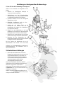
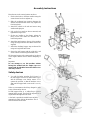
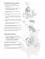
Anleitung zur fachgerechten Endmontage
Gehen Sie bei der Endmontage wie folgt vor:
Stellen Sie die Maschine wie abgebildet auf den
Boden.
1. Radachse am Grundsegment anbringen und
vorerst nur locker anschrauben.
2. Radabdeckung mit den Schraubenschlitzen
zwischen Radachse und Seitensegment schieben,
die 4 Befestigungsschrauben fest anziehen.
3. Laufräder montieren und mit den beiliegenden
Klappsplinten sichern.
4. Fußständer hochklappen und mit den 2
beiliegenden Schrauben befestigen.
5. Stecken Sie die beiden Holme in den
Grundrahmen und schrauben Sie diese am
Grundrahmen fest. Kippen Sie die Maschine in
die waagerechte Stellung.
6. Hängen Sie den Haupttrichter in die beiden
Scharniere ein und fixieren Sie diesen mittels der
beiliegenden kurzen schwarzen Sternschraube.
7. Hängen Sie den Auswurftrichter ein und fixieren
diesen mit der langen schwarzen Sternschraube.
8. Montieren Sie den Seitentrichter mit der
beiliegenden Schraube und fixieren Sie diesen mit
der langen schwarzen Sternschraube.
Bei der Version mit Benzinmotor ist vor der
Inbetriebnahme das Motoröl sowie das Benzin
Achtung: Vor der Inbetriebnahme ist unbedingt die
Bedienungsanleitung des Schredders sowie des
Motors durchzulesen.
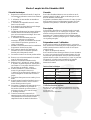
Sicherheitsvorrichtungen
1. Beim seitlichen Einfülltrichter sowie beim
Haupttricher kombiniert mit dem Auswurftrichter
sind Sicherheitsschalter®+¯ montiert. Die
Schalter werden betätigt durch die Schrauben
¬+-.Somit wird ein Anlaufen der Maschine
verhindert solange nicht alle Trichter
ordnungsgemäß verschlossen sind.
Wir weisen ausdrücklich darauf hin, daß keine
Änderungen an den Sicherheitsvorrichtungen der
Maschine vorgenommen werden dürfen.
In den beiden Trichtern befindet sich jeweils ein
Gummischutz, um ein evtl. Herausschleudern von
Schnittgut zu verhindern.
Seitlich am großen Haupttrichter befindet sich ein
, um gefahrlos Laub sowie sperriges
Grüngut nachstoßen zu können.

2
Bedienungsanleitung Schredder 4000 Profi
Sicherheitstechnische Grundregeln
1. Beachten Sie neben den Hinweisen in der
Bedienungsanleitung die allgemein gültigen
Sicherheits- und Unfallverhütungsvorschriften!
2. Jugendliche unter 16 Jahren dürfen die Maschine
nicht bedienen.
3. Der Benutzer ist gegenüber Dritten im
Arbeitsbereich verantwortlich.
4. Der Aufenthalt im Gefahrenbereich der Maschine,
insbesondere im Auswurfbereich, ist verboten.
5. Die angebrachten Warn- und Hinweißschilder geben
wichtige Hinweise für den gefahrlosen Betrieb: die
Beachtung dient Ihrer Sicherheit.
6. Der Bediener muß auf eng anliegende Kleidung
achten und hat Gehörschutz, Handschuhe,
Schutzschuhe und Schutzbrille zu tragen (ggf. auch
Gesichtsschutz).
7. Beim Betrieb müssen sämtliche Schutz-
einrichtungen in Schutzstellung befestigt sein.
8. Für das Starten der Maschine sind die speziellen
Hinweise des Motorherstellers zu beachten.
9. Verbrennungsmotoren nicht in geschlossenen
Räumen laufen lassen.
10. Machen Sie sich vor dem Arbeiten mit der
Funktionsweise der Maschine vertraut.
11. Vorsicht!! Arbeitswerkzeuge laufen nach.
12. Beim Umgang mit Benzin ist Vorsicht geboten, es
besteht erhöhte Brandgefahr. Niemals in der Nähe
von offenen Flammen, zündfähiger Funken sowie
heißer Motorteile Kraftstoff nachfüllen. Beim
Auftanken nicht rauchen.
13. Vor dem Auftanken Motor abstellen. Benzin nicht in
geschlossenen Räumen nachfüllen. Kraftstoff nicht
verschütten! Zur Vermeidung von Brandgefahr die
Maschine sauber halten.
14. Die Maschine muß auf festem ebenem Untergrund
stehen.
15. Vor dem Verlassen der Maschine ist der Motor
abzustellen sowie der Benzinhahn zu schließen. Bei
der Version mit E-Motor ist der Netzstecker zu
ziehen.
16. Wartungs- und Reinigungsarbeiten sowie das Ab-
nehmen oder Abklappen der Schutzeinrichtungen
dürfen nur bei Stillgesetzten Motor und nur,wenn
Zündkerzenstecker oder Netzstecker abgezogen sind,
vorgenommen werden.
17. Alle Schutzvorrichtungen des Keilriemenantriebes
müssen vorschriftsmäßig angebracht sein, da sonst
die Sicherheitsschalter ein Anlaufen der Maschine
verhindern.
Garantie
Gemäß unseren Garantiebestimmungen leisten wir auf den
Schredder 4000 Profi ab Verkaufsdatum eine 1 jährige
Garantie bei der Verwendung im privaten Bereich, bei der
Verwendung im kommerziellen Bereich beträgt die Garantie
½ Jahr. Garantie kann nur anerkannt werden, wenn die
beiliegende Verkaufsnachricht ausgefüllt an den Hersteller/
Importeur gesandt wird sowie bei einer Garantiereparatur der
Garantieschein vorgelegt wird.
Beschreibung
Der Schredder 4000 Profi ist ein universell einsetzbarer
Schredder, ausgerüstet mit einem Hammerwerk und einer
Schnitzelscheibe. Das Gerät ist geeignet bis max. 8cm
Astdurchmesser über den Seitentrichter sowie
Grünmaterialien, Laub und dünnere Äste über den
Hauptrichter (weitere Beschreibung im Hauptteil).
Vorbereitung vor dem Einsatz
Vor Inbetriebnahme des Gerätes, muß sichergestellt werden,
daß die beiden Trichter frei von Fremdkörpern sind. Bei der
Version mit Benzinmotor ist unbedingt der korrekte Stand
des Motoröls zu Überprüfen (Bedienungsanleitung des
Motorherstellers beachten).
Bei der Version mit Elektromotor ist die Drehrichtung zu
beachten. Sollte eine Umpolung erforderlich sein, darf diese
nur von einen Elektrofachmann durchgeführt werden. Bei
Drehstromgeräten sollte ein Kabeldurchmesser von 5x 1,5
Quadratmillimetern nicht unterschritten werden. Die
Steckdose sollte mit 16A träge abgesichert sein.
Keilriemenspannung überprüfen (siehe hierzu im Kapitel
"Arbeitsanweisung").
Technische Daten
Type 4000
380V
4000
Benzinmotor
Antrieb Elektromotor
3x 400V
3,7 KW
Honda GX 270
6,6 KW
Absicherung 16A träge
Schneidhämmer 32 32
Räumhämmer 4 4
Hobelmesser 1 1
Sicherheitsschalter 2 2
Horizontalgrill (Option)
Als Option kann ein zusätzlicher Horizontalgrill
bestellt werden.
Bei zusätzlichem Horizontalgrill erreichen Sie
eine Feinzerkleinerung von trockenen
Holzmaterialien.
Fragen Sie Ihren Fachhändler.

3
So wird gearbeitet:
• Weichmaterialien, Grünzeug sowie kurze Zweige
werden immer über den Vertikaltrichter verarbeitet.
• Astmaterial und längere Zweige müssen über den
Seitentrichter verarbeitet werden.
• Beginnen sollten Sie mit Ihrer Arbeit erst, nachdem der
Motor auf vollen Touren läuft. Sollte während Ihrer
Arbeit die Motordrehzahl einmal stark absinken,
warten Sie mit dem Nachschieben von neuem Material
auch wieder, bis der Motor auf vollen Touren läuft.
• Durch starkes Eindrücken von Schneidmaterial in die
Maschine kann die Maschine beschädigt werden. Durch
solche Bedienung hervorgerufen Schäden sind keine
Haupttrichter (Vertikaltrichter)
Material, welches in den Hauptrichter gefüllt wird, gelangt
direkt auf die Hammermühle.
Aus diesem Grund sollte hier nur weiches Schnittgut
verarbeitet werden, z.B. Laub, Obst, Gemüse,
Küchenabfälle, Stroh sowie kurze Zweige.
Achtung:
Das in den Haupttrichter eingeworfene Schnittgut wird
von den umlaufenden Schneidhämmern mit großer Wucht
erfaßt und ruckartig eingezogen. Längeres Grünzeug sollte
somit aus Sicherheitsgründen losgelassen werden, bevor es
von den Schlaghämmern erfaßt wird. Als Schiebehilfe
benutzen Sie bitte stets den Nachstoßhebel am
Haupttrichter.
Seitentrichter (Astschneider)
Alles Astmaterial, einschließlich längerer Zweige, müssen
ausschließlich über den Seitentrichter eingeführt werden.
Dickere Äste werden einzeln und behutsam über den
Seitentrichter eingeführt damit die Motordrehzahl nicht zu
weit absinkt.
Horizontalgrill (Option)
Beim Verarbeiten von trockenem Holzmaterial wird durch
das Montieren des Horizontalgrills eine Feinzerkleinerung
des Schneidmaterials ermöglicht.
Achtung:
Feuchtes und leicht erdiges Holzmaterial darf niemals mit
diesen vorgeschalteten Horizontalgrill verarbeitet werden.
Die Maschine würde augenblicklich verstopfen.
Merke:
Nasses Grünzeug, Laub, langes Gras, Küchenabfälle
immer ohne bzw. bei heruntergeklappten Horizontalgrill
verarbeiten.
Verhinderung eines Rückstaus beim
Auswurf
Es ist darauf zu achten, daß zwischen dem Auswurftrichter
und dem Boden genug Freiraum bleibt.
Achten Sie deshalb bitte darauf, daß unter dem Auswurf
immer genug Freiraum bleibt.
Der Schredder 4000 Profi ist kein
Erdaufbereiter!!
Es darf keine Erde, kein halbverottetes Laub oder
halbverotteter Kompost aufbereitet werden
Wartung des Schredder 4000 Profi
• Arbeiten an der Maschine sollten grundsätzlich nur bei
ausgeschaltetem Antrieb und stillstehendem Motor
vorgenommen werden. Netzstecker bzw.
Zündkerzenstecker ziehen.
• Nach ca. 1 Betriebstunde sind alle Schrauben auf festen
Sitz zu überprüfen.
• Keilriemen regelmäßig auf korrekten Spannung
Wenden/ Auswechseln der
Schlaghämmer
(Diese Arbeit sollte ausschließlich von einer Fachwerkstatt
durchgeführt werden).
• Motor ausschalten bzw. Netzstecker herausziehen.
• Auswurftrichter entfernen.
• Keilriemenabdeckblech ± abschrauben
• Herausziehen der zwei (bei montierten Horizontalgrill
vier) Klappsplinten ².
• Herausziehen der Fixierstäbe - und herunterklappen
des Vertikal -- sowie Horizontalgrills ¬ (falls
montiert).
• Demontieren Sie die Wellenabdeckung ´.Treiben Sie
den Spannstift µ heraus.
Die Hammerachse wird von rechts nach links
herausgeschoben. Achten Sie auf die Reihenfolge der von
Ihnen demontierten Teile (auf einem Seil nacheinander
einfädeln). Nach dem Wenden der Schlaghämmer werden
die Distanzhülsen sowie die gewendeten Schlaghämmer
wieder in der gleichen Reihenfolge montiert.
Der Sicherungsring wird wieder montiert und mit einem
neuen Spannstift gesichert.
Nach dem Wenden oder Auswechseln sind alle Bauteile
auf ihre Leichtgängigkeit zu überprüfen.

4
Gegenmesserwechsel
Sollte das Gegenmesser stumpf sein, kann es gewendet
werden.
• Motor ausschalten bzw. Netzstecker herausziehen.
• Seitentrichter am Haupttrichter arretieren.
• Die Gegenmesserschrauben lösen.
• Gegenmesser wenden, bei starker Abnutzung oder
Beschädigung austauschen.
• Schrauben fest anziehen.
Nach dem Wenden sollte das Spaltmaß zwischen dem
Messer sowie dem Gegenmesser überprüft werden. Das
Maß sollte 2mm betragen; ist eine Korrektur notwendig
kann durch Unterlegen von Distanzscheiben das Maß
Messerwechsel
Motor abschalten bzw. Netzstecker herausziehen.
Auswurftrichter entfernen.
Einfülltrichter zurückklappen und Hammermühle von
Hand drehen bis das Seitenmesser oben ist.
Die untere Messerschraube lösen und herausnehmen.
Vertikal- und Horizontalgrill herunterklappen.
Hammermühle drehen, bis das Messer durch den Auswurf
zu erreichen ist.
Die zweite Messerschraube entfernen und das Messer
herausnehmen.
Das neue Messer zuerst mit der äußeren Schraube locker
anschrauben. Die Schnittfläche weist nach unten
Nun schwenken Sie das Messer in die Arbeitsposition (in
Pfeilrichtung) die Schneidfläche weist dann nach oben und
die angefaste Seite des Messers zur Hammermühle.
Nach der Montage sind alle Schrauben gewissenhaft
festzuziehen.
Störungsbeseitigung
Die Maschine läuft nicht an:
Überprüfen ob Benzin im Tank ist bzw. das
Zuleitungskabel in Ordnung ist. Die Haussicherung ggf.
kontrollieren.
Sicherheitsschalter überprüfen, sind die
Betätigungsschrauben für die Sicherheitsschalter korrekt
eingeschraubt? Eine nicht korrekt eingeschraubte
Betätigungsschraube für die Sicherheitsschalter führt zu
einem Unterbrechen des Stromkreises.
Sollten Sie die Störung nicht beseitigen können, wenden
Sie sich bitte an Ihren Fachhändler.
Der Motor schaltet sich nach einiger
Betriebszeit selbständig ab:
Bei der Version mit Elektromotor könnte der Motor zu
heiß sein, so daß die Thermosicherung zum Einsatz
kommt. In diesen Fall lassen Sie bitte den Motor Abkühlen
und versuchen Sie es erneut. Sollte das Zuleitungskabel
heiß sein, überprüfen Sie, ob Sie den angegebenen
Kabelquerschnitt verwenden (5x 1,5mm) oder ob die
Zuleitung zu lang ist.
TIP: nur kurze Kabel mit großem Querschnitt verwenden.
Der Motor läuft nicht an und
brummt/quietscht:
• Prüfen Sie, ob sich die Hammermühle frei durchdrehen
läßt. Reinigen Sie den Bereich der Hammermühle, so
daß sich die Hammermühle frei durchdrehen läßt.
• Prüfen Sie die Keilriemenspannung und spannen Sie
den Keilriemen ggf. nach.
Sollte die Maschine nicht anlaufen wenden Sie sich an
Ihren Fachhändler.
Spannen des Antriebskeilriemens
Der Antriebskeilriemen sollte nach einer Laufzeit von 0,5-
4 Stunden erstmalig nachgespannt werden.
Danach sollte der Keilriemen regelmäßig auf seine
korrekte Spannung geprüft werden. Der Keilriemen ist
richtig gespannt, wenn er sich um ca.1,5cm auf der langen
gerade eindrücken läßt.
Die Spanneinrichtung für den Antriebskeilriemen befindet
sich unter der Maschine. Nach dem Lösen der
Kontermutter kann der Keilriemen mittels Spannschraube
nachgespannt werden.
Das geschredderte Material ist zu fein:
• Sollte der Horizontalgrill eingebaut sein, klappen Sie
diesen heraus.
• Prüfen Sie die Hämmer; sind die Kanten abgerundet
müssen diese gedreht bzw. getauscht werden.
• Beim Arbeiten mit dem Seitentrichter, prüfen Sie das
Messer sowie das Gegenmesser, ggf. Austauschen oder
Schärfen. Das Spaltmaß des Messers zu der
Gegenschneide sollte 2 mm betragen , sollte das Maß
nicht korrekt sein, können Sie das Spaltmaß durch
unterlegen von Distanzescheiben korrigieren.

5
Assembly Instructions
Place the unit in the vertical position as shown.
1. Fit the wheel axle to the base machine using the
screws shown but do not tighten up. .
2. Slide the mudguard into position between the
chassis and axle brackets. Now fully tighten the
four fixing bolts.
3. Attach the wheels to the axle and secure using
washers and split pins.
4. Lift up the foot stand (as shown arrowed) and
tighten the fixing screws.
5. Fit the two handles to the chassis, tighten the
fixing screws and rotate the machine into a
horizontal position..
6. Attach the main hopper to the top of the machine
using the hinges and the short black hand screw
supplied.
7. Attach the discharge hopper, snap it shut and fix
using one long black hand screw.
8. Secure the side hopper with the collar bolt and
secure with the second long black hand screw.
Fill the petrol engine with correct grade oil as shown
in the engine manual and full before attempting to
start.
Important:
Do not attempt to use this machine without
having first studied both the Engine Operators
manual and the Shredder Instruction Information
and safety features.
Safety devices
1. You will find safety switches ®+¯ located on
the side hopper as well as on main intake hopper
and the discharge cover. Safety screws ¬+-
operate the switches, so that the machine cannot
start until all hoppers and covers are all correctly
fitted.
Under no circumstances should any changes be made
to any of these safety devices.
In both hoppers there is a rubber flap to prevent
material being ejected. The should be inspected on a
regular basis and replaced when worn.
A feed tool is provided to enable leaves and bulky
material to be safely fed into the machine. This is
stored at the side of the main

6
Instruction manual for Shredder 4000 Profi
Basic Rules for safety
1. As well as carefully following the safety
instructions it is important to adhere to all current
safety legislation!
2. No one under sixteen years of age should operated
this machine. New, young or inexperienced
operators must receive thorough training and never
work alone.
3. The machine operator should not allow anyone else
within the working area of the machine
4. No one should be near the discharge area of the
machine at any time when the machine is working.
5. Warning stickers are provided to ensure safe
operation. Do not ignore the advice given.
6. Operators must wear suitable protective clothing,
which is close fitting, and be provided with eye and
ear protection. Special attention must be paid to
good fitting suitable gloves and correct safety shoes.
7. All safety devices must be in operation throughout
the machine. Do not attempt to bypass them or
otherwise operate the machine when they are
defective.
8. Read the engine operators manual to ensure
satisfactory and safe engine performance.
9. Do not run the petrol engine in enclosed spaces.
Always ensure there is adequate ventilation.
10. Fully understand the correct function of the machine
before attempting to start.
11. Rotating parts, particularly the chopping motor, will
continue to rotate for a short time after stopping the
engine.
12. Be very careful when handling with fuel particular
do not re-fuel near naked flames, any possible
ignition source or when the engine is hot. Do not
smoke when re-fuelling.
13. Before re-fuelling stop the engine and allow to cool.
It is always better to refuel the engine before work
whilst the engine is cold. Do not re-fuel in enclosed
areas and avoid fuel spillage by using correct
containers and funnels. In particular, keep the
machine clean to avoid the build up of inflammable
dirt.
14. Operate only on solid, firm ground.
15. Never leave the machine unattended with the engine
running and always shut off the fuel tap when not in
use. Disconnect the main supply plug on units with
electric motors.
16. With electric powered machines, always disconnect
the main supply by removing the plug before
working on the unit. With petrol engines, always
disconnect the sparking plug lead when working on
the machine.
17. The belt drive and safety switches must be correctly
attached, otherwise the safety switch will prevent the
machine from starting.
Warranty
As covered in our conditions of sale, we guarantee the
Shredder 4000 Profi for a period of one year from purchase
date for private use and six month for professional and
commercial use. Warranty is only valid if enclosed Warranty
Registration Form submitted for any repairs. In particular
this damage through misuse or operation without safety
features..
Description
The Shredder 4000 Profi is equipped with a set of shredding
hammers and a shredding disk. The shredding disk handles
branches etc up to a maximum of 8cm diameter, as well as
twigs, leaves and other material which can be fed through the
main hopper.
Preparations for work
Before using the machine, check that nothing has been left in
either of the two feed hoppers. In case of petrol engine
machines, check that the engine is full of fuel and oil (please
check engine manufacturers manual for details). For electric
powered units it is vital to check that the rotation direction is
correct, if not have the correct wiring carried out by a
qualified electrician. In the case of three phase motors, ensure
that the cable has five conductors of at least 1.5 square mm
cable section and use a 16 A fuse.
Check the tensioning of the V-belt.
Technical Data
Type 4000
380V electric
4000
petrol-engine
Engine 3x 400V
3,7 kW
Honda GX 270
6,6 kW
Protection 16A fuse
Cutting hammer 32 32
Clearing hammer 4 4
Cutter blades 1 1
Safety switches 2 2
Cutting screen (optional)
A cutting screen can be used to ensure that dry
woody material will be very finely shreddered.
Please check with your supplier for technical
information.

7
Working system
• Soft material, leaves and twigs can be shreddered
directly in the main hopper.
• Thick material and branches must be fed using the side
hopper.
• Do not operate the machine unless the engine, or
electric motor, is running at full speed. Do not allow
the engine to labour but feed at a rate which allows it
to maintain rates speed throughout the operation cycle.
• Do not force material into the hopper as this could
overload the machine and cause damage not covered by
the warranty.
Main Hopper
Material fed into the main hopper, reaches the hammers
directly. Because of this only light weight material should
be fed in this way.
Important:
The hammer action generally pulls material through the
hopper without manual assistance. In the case of blockages
use the feeding tools supplied and under no circumstances
attempt to push it down manually.
Side Hopper (Branch-Cutter)
Use this for all long material and thick branches up to the
capacity limit of the machine. Do not force material in so
fast that the engine is forced to labour.
Cutting screen (optional)
This should only be used with dry material which is then
re-chopped until it is quite fine..
Important:
Never use this for damp material, which will otherwise
block up and jam it.
Note:
Damp material should be shreddered with the screen
folded down in the horizontal position.
Prevention of pile-up during ejection
Keep outlet clear. Always check that there is enough space
from outlet for the material being chopped.
The Shredder 4000 Profi is not a soil
processing machine
Do not shred earth, manure or compost in this unit.
Maintenance of the Shredder4000
• Only work on the machine if the mains plug or spark
plug lead are disconnected.
• Tighten the hardware after the first hour of use and
then at regular intervals until stable
• Regularly check belt tension, particularly after heavy
work.
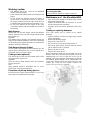
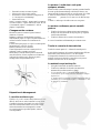
Turning or replacing hammers
(This work should only be carried out by trained
personnel)
• Stop the machine or remove the supply plug or spark
plug as appropriate
• Remove the discharge hopper.
• Remove the V-belt cover ±.
• Pull out the two (if screen is fitted four) pins ².
• Pull out the grille belts - and fold down the vertical
grill - and the screen ¬ (if fitted).
• Remove the shaft cover ´.
• Remove the location pin µ.
Extract the hammer shaft from the left hand side of the
machine. Take care to keep the removed parts in order by
threading them on a wire or other bar so they can be
replaced in the correct sequence. After turning or replacing
the hammers, please assemble all the components in the
correct order. Refit the safety ring and secure with a new
location pin. Check for free rotation whenever the
hammers have been turned or replaced..

8
Changing sheer bars
If the sheer bar is worn, you can turn it over.
• Stop the engine and disconnect the spark plug or
remove the supply plug on electrically powered
machines.
• Lock the side hopper to the main hopper
• Slacken the sheer bar screws.
• Turn the sheer bar. If it is damaged or worn out,
replace it.
• Fully tighten the mounting screws.
After re-positioning or replacing the sheer bar measure the
gap between the cutting blades and sheer bar which should
be 2mm. If the clearance is greater, add spacers to correct.
Changing of cutter blades
• Stop the engine or remove the spark plug, or remove
the supply plug for electrically powered units.
• Remove the discharge hopper
• Tilt the main hopper backwards.
• Turn the hammer shaft by hand until side blade is on
top.
• Slacken the blade jacking bolt and remove it.
• Fold down the vertical and horizontal screens.
• Turn the hammer shaft until you can reach the blade
through the outlet.
• Loosen the 2nd blade screw and remove the blade
• Fit the new blade loosely with the outer screw only.
The cutting edge should be pointing downwards.
• Turn the blade into cutting position so that the blade is
now pointing upwards.
• Fully tighten the blade mounting bolts.
Trouble shooting
The unit does not start:
• Check the engine fuel or for electrical units the supply
plug fuse and supply.
• Check all the safety switches and ensure that they are
correctly installed as they will prevent the engine
starting. If you cannot solve the problem, please
contact your dealer.
The electric engine stops after short
period:
The motor could be over heated so that the thermostatic
cut out has operated. In this case, wait until motor has
cooled down and try again
If the supply plug is hot, please check the cable diameter
(5 x 1,5mm) and the correct fitting of the wires into the
plug.
Note:
Use only short cable with a conductor size of 1,5mm or
greater. Long cables cause both voltage drop and an
increase in current which way blow fuses
Engine will not run at full speed or gives
sings of distress:
• Check that the hammer mill shaft can turn freely and
clean the area to ensure that no blockage can occur.
• Correct the belt tension if necessary.
If the unit still does not work, please contact your dealer.
V-belt tension
You should check the V-belt tension more frequently
when the machine is new and then, thereafter, at regular
intervals of no more than 4 hours. The V-belt tensioner is
located towards the bottom of the machine and can be
accessed by slacking the lock nut. the tension of the V-belt
can be adjusted by taking up the tension of the screw
provided.
Chopped Material is too fine for intended
use:
• If the horizontal screen is refitted, remove it by folding
it down.
• Check the hammers. If edges are blunt, turn or change
them to sharp edges.
• If the side hopper is in use, check the cutter blades and
sheer bar. Sharpen or change these as necessary. Ensure
that the clearance between the cutter blade and sheer
bar is 2mm, shim to correct.

9
Procédez de la faςςon suivante
Posez la machine sur le sol, comme décrit.
1. Installez l’ arbre à l’élément de base en serrant
légèrement les vis.
2. Poussez la tôle de protection de roue avec le pas de
vis entre l’ arbre et le segment de côte.
Serrez bien les 4 vis de fixation.
3. Montez les roues de roulement avec les goupilles
rabattantes ci-jointes.
4. Relevez le support de pieds et fixez-le avec les deux
vis ci-jointes.
5. Enfoncez les deux montants dans le cadre de base et
vissez les bien. Remettez la machine dans la position
horizontale.
6. Posez l’entonnoir de base dans les deux charnières et
fixes-les au moyen de la petite vis à fentes en croix noir
ci-jointe.
7. Accrochez l’ entonnoir de sorti et fixez-le avec la
grande vis à fentes en croix noir.
8. Montez l’entonnoir latéral avec la vis ci-jointe et fixez-
le avec la grande vis à fente en croix noir.
Avant la mise en marche du model à moteur à essence il est
nécessaire de mettre l’essence et l’huile de moteur.
Attention: Avant la mise en marche il faut absolument lire
le mode d’emploi du shredder et du moteur.
Dispositifs de sécurité
1. Pour l´entonnoir latérale et l´entonnoir principal
combinée avec l’ entonnoir d’ éjection des boutons de
sécurités 3 + 4 sont installés.
Les boutons de sécurités sont actionnés par les vis 1 +
2. Tant que les entonnoirs ne sont pas placés
correctement, la machine ne démarre pas.
Nous signalons qu’aucun changement ne doit être apporté
aux dispositifs de sécurité de la machine.
Dans chacun des deux entonnoirs se trouve un caoutchouc
de protection pour éviter une éventuelle éjection des
déchets de sciage.
Sur le côté de l’entonnoir de base se trouve un levier pour
pouvoir rajouter sans danger branches et feuillage.

10
Mode d‘ emploi du Bio-Shredder 4000
Sécurité technique
1. Respectez les instructions du mode d’ emploi et
les instructions préventives contre les accidents et
ité.
2. L’ utilisation de cette machine est interdite au
moins de 16 ans.
3. L’ utilisateur est responsable envers d’ autres
dans la zone de travail.
4. Il est interdit de se placer dans la zone de danger
de la machine surtout dans la zone
d’ éjection.
5. Les tableaux indicateurs et les signaux de danger
installés donnent des indications importantes
pour un fonctionnement sans danger. Pour votre
sécurité respectez-les.
6. L’ utilisateur doit absolument porter des
staucorps, une protection
acoustique, des gants, des chaussures de sécurité
et des lunettes de protection (protection du
visage, si nécessaire)
7. Pendant le fonctionnement toutes les installations
de protection doivent être en place.
8. Pour la mise en marche de la machine il est
nécessaire de suivre les indication spéciales
données par le fabriquant du moteur.
9. Les moteurs à essence ne doivent pas être utilisés
10. Exercez-vous au fonctionnement de la machine
avant d’ effectuer le travail.
11. Attention: Les machines marchent à vide.
12. Prudence avec l’ utilisation d’ essence. Risque
d’ incendie. Ne jamais rajouter d’ essence près d’
une flamme ou d’ une partie chaude du moteur.
Ne pas fumer en versant de l’ essence.
13. Avant de remettre de l’ essence éteindre le
moteur. Ne pas remplir le réservoir à
l’ intérieur. Ne pas renverser du carburant. Pour
éviter les dangers d’ incendie tenir la machine
propre.
14. La machine doit reposer sur une surface plane et
stable.
15. Avant de quitter la machine éteindre le moteur et
fermer le robinet à essence. Pour le modèle à
moteur électrique retirer la prise.
16. Les travaux d’ entretien et de nettoyage ainsi que
le retrait des installations de protection ne
doivent être effectués que moteur éteint et
seulement si la prise ou la cosse de bougie
d’ allumage est retirée.
17. Toutes les mesures de protection de la
transmission par courroie doivent être montées
correctement sinon les boutons de sécurité
empêchent la mise en marche de la machine.
Garantie
Pour le Bio-Shredder 4000 nous vous accordons un an de
garantie à partir de la date d’ achat en utilisation privée et 6
mois en utilisation commerciale.
La garantie et seulement valable si la notice de vente ci-jointe a
bien été rempli et envoyé au fabriquant / importer. En cas de
réparation sous garantie, le certificat de garantie doit être
Description
Le broyeur Bio-Shredder est un shredder à emploi universel,
équipé de marteaux et d’ un couteau pour coupe fine : Cette
machine est fait pour des branches de 8,0 cm de diamètre
maximum par l’ entonnoir latéral et pour feuillages et petites
branches par l’ entonnoir principale (pou d’ autres description
voir la partie principale).
Préparation avant l’ utilisation
Avant la mise en marche du Shredder assurez –vous que les
deux entonnoirs ne contiennent pas de objets étrangers. Pour le
model à moteur à essence vérifiez le niveau d’ huile (tenir
compte du mode
d’ emploi du fabriquant du moteur).
Pour le model à moteur électrique observez le sens de rotation.
Au cas ou une inversion des pôles serrait nécessaire, elle doit
être effectuée par un électricien. Pour les moteurs électrique
triphasé utilisez un câble d’ au moins 5 x 1,5 mm. La prise doit
être munie d’ un fusible à action retardée de 16 Ampère.
Contrôlez la tension de la courroie (voir au chapitre
Instruction de travail.
Instruction technique
Type 4000
380V
4000
moteur à essence
Accélération Moteur électrique
3 x 400V
3,7 kW
Honda GX 270
6,6 kW
Protection 16 A action retardée
Marteaux tranchant 32 32
Fer de rabot 1 1
Boutons de sécurité 2 2
Grille horizontale (option)
En option, une grille horizontale supplémentaire peut être
commandée. Avec cette grille vous obtenez une coupe très
fine de bois sec.
Demandez à votre dépositaire.

11
Mode de travail
• Matériaux souples, petite branches doivent
toujours être rempli par l’ entonnoir vertical.
• Branchages et branches longues doivent toujours
être rempli par l’ entonnoir latéral.
• Commencez votre travail après que le moteur
marche à grande vitesse. Il peut arriver que le
moteur ralentisse pendant le travail, dans ce cas
attendez un peu avant de remplir l’ entonnoir
jusque’ à ce que le moteur redémarre à grande
vitesse.
• Une trop forte pression sur la coupe peut entraîner
des dommages sur la machine. Ces dommages ne
sont pas sous garantie.
Entonnoir principal (entonnoir vertical)
Les matériaux que vous remplissez par l’ entonnoir
principal tombent directement sur le concasseur à
marteaux. Pour cette raison n’ utilisez que des
matériaux mous comme feuillage, fruits, légumes,
déchets de cuisine, paille et branches courtes.
Attention:
Les matériaux déposés dans l’ entonnoir principale
sont happés violemment par les marteaux tranchants et
entraînés par à-coup. Par mesure de sécurité le
feuillage long doit être lâché avant
d’ être pris par les marteaux. Pou vous aider à pousser
les matériaux n’ utilisez que le levier installé sur l’
entonnoir principale.
Entonnoir latéral
(coupe de branche)
Tous les branchages et branche longues doivent être
introduits par l’ entonnoir latéral. Les grosses
branches doivent être introduites une à une et avec
beaucoup de précautions afin que la vitesse du moteur
ne diminue pas trop.
Grille horizontale (option)
Le montage de la grille horizontale permet d’ obtenir
une coupe très fine des matériaux de bois secs.
Attention:
Les bois humides et terreux ne doivent en aucun cas
être introduits dans la machine munie de la grille
horizontale. La machine peut s’ engorger
Remarque:
Branchage humide, feuillage, herbe longue, déchets de
cuisine ne peuvent pas être introduits que sans ou
avec grille horizontale abaissée.
Comment éviter un encombrement
L’ espace libre entre le sol et l’ entonnoir d’ éjection
doit toujours être suffisant. Observes cette précaution.
Le Bio-Shredder 4000 n’ est pas une machine pour traiter la
terre!
Il est interdit de traiter terre et feuilles décomposées,
compost décomposé
Entretien du broyeur Bio-Shredder 4000
• Les travaux sur la machine doivent seulement être
effectués moteur éteint. Retirez la prise ou la cosse de
bougie d’ allumage.
• Après 1 heure d’ utilisation vérifiez la fixation de toutes
les vis.
• Vérifiez régulièrement la tension de la courroie.
Inversion / Remplacement des marteaux
(Ce travail ne peut être effectué que par un garage spécialisé)
• Eteindre le moteur et retirez la prise.
• Retirer l’ entonnoir d’ éjection.
• Dévisser le tôle de protection de la courroie
±
• Retirer les deux goupilles rabattantes ²
(4 si la grille
horizontale est montée)
• Retirez les tiges de fixation ³
et rabattre la grille verticale
-
et horizontale ¬
(si elle est montée)
• Monter la cache-palier (dispositif d’ étanchéité d’ arbre)
• Enlever la goupille de sérrage µ
.
Pousser l’ arbre des marteaux de droite à gauche pour le sortir.
Observer l’ ordre des pièces que vous démontez (les enfilez sur
une corde).
Après l’ inversion des marteaux remontez dans le même ordre
les douilles d’ écartement ainsi que les marteaux retournés.
Remonter le cir-clip et fixez-le avec une nouvelle goupille de
sérrage.
Après avoir inversé ou changé les pièces, vérifiez leur
souplesse.

12
Changement de contre couteau
Si le contre couteau est émoussé, vous pouvez
• Eteindre le moteur ou retirez la prise.
• Dévissez les vis du contre couteau.
• Retournez le contre couteaux ou remplacez-le
s’ il est trop usé ou endommagé.
• Serrez bien les vis.
Après l’ inversion vérifiez l’ espace entre le couteau et
le contre couteau. L’ espace doit être de 2 mm. En cas
d’ inexactitude, réglez l’ écartement à l’ aide de
plaques d’ espacement.
Changement de couteaux
Eteindre le moteur ou retirez la prise. Retirez l’
entonnoir d’ éjection.
Rabattre l’ entonnoir de remplissage et tourner
manuellement jusque’ à ce que le couteau latéral soit
en haut. Dévissez et retirez la vis inférieure du
couteau.
Tournez le broyeur jusque’ à ce que le couteau puisse
être atteint par l’ orifice d’ éjection.
Retirez la seconde vis et le couteau.
Visser légèrement le nouveau couteau par la vis
extérieure, la face coupante vers le bas.
Mettre alors le couteau dans la position de travail
(sens de la flèche), la face coupante vers le haut et le
coté lamé du couteau vers le broyeur. Après le
montage serrez soigneusement les vis.
Réparation de dérangement
La machine ne démarre pas:
Vérifiez s’ il y a de l’ essence dans le réservoir ou si le
câble d’ arrivé est en ordre. Contrôlez le coup circuit.
Contrôlez le boutons de sécurité. Les vis de contact
sont-elles correctement serrées? Une vis de contact
mal serrée entraîne une interruption du courant.
Au cas ou la panne ne peut être réparée, contactez
votre dépositaire.
Le moteur s’ arrête tout seul après
quelques minutes
Dans le model à moteur électrique le moteur pourrait chauffer
de sorte que die thermosicherung se déclenche. Dans ce cas
laisser refroidir le moteur et faite un nouvelle essai. Si le câble
d’ arrivé est chaud vérifiez si vous avec utilisé la coupe
transversale prescrit (5 x 1,5 mm) ou si le câble est trop
long.
Conseil: n’ utilisez que du cable court avec une grosse
Le moteur ne démarre pas et vrombit /
graince
• Vérifiez si le broyeur se laisse tourner sans interruption.
Nettoyez la zone de travail du broyeur pour qu’ il puisse
tourner sans problèmes.
• Vérifiez la tension de la courroie et la retendre si
Au cas ou la machine ne démarrerait pas contactez votre
Tendre la courroie de transmission
Tendre la courroie après 0,5 – 4 heures de travail pour la
Après vérifiez la tension de la courroie régulièrement. Elle est
bien tendue si elle laisse tirer sur 1,5 cm de longueur.
Le dispositif de fixation de la courroi se trouve sous la
machine. Après avoir devissé le contre écrou vous pouvez
retendre la courroi avev la vis de sérrage.
Le matériel coupé est trop fin
• Si la grille horizontale est montée retirez-la.
• Vérifiez les marteaux si les bords sont arrondi les
marteaux doivent être tournés ou changé.
• Si vous travaillez avec l’ entonnoir latéral vérifiez le
couteau ainsi que le contre couteau si nécessaire changez
aiguisez-les.
L’ espacé entre le couteau et le contre couteau doit être de
2 mm. En cas d’ inexactitude, réglez l’ écartement à l’ aide
de plaques d’ écartement.

13
EC-Certificate of Conformity
confirming to EEC Directions 89/392/EWG
The signatory,
Fa. Telsnig Forst- & Gartentechnik
Dörnbergstr.27
34233 Fuldatal/ Ihringshausen
declares on its own responsability that below listed machine
HERKULES Schredder 4000 Profi
which this declaration refers to, complies with the following regulations and standards
Machine directive 89/392/EWG
Electromagnetic Compatibility 89/336/EWG
Low voltage directive 73/23/EWG
Fuldatal den 4.02.1999 Adolf Telsnig
Ort und Datum der Ausstellung Name und Unterschrift des
Befugten
EG-Konformitätserklärung
entsprechend der EG-Richtlinie 89/392/EWG
Der unterzeichnete,
Fa. Telsnig Forst- & Gartentechnik
Dörnbergstr.27
34233 Fuldatal/ Ihringshausen
erklärt in alleiniger Verantwortung,
HERKULES Schredder 4000 Profi
für das diese Erklärung gilt, den nachfolgenden Standarts bzw. sonstigen Normen entspricht.
EG- Richtlinie 89/392/EWG
EG-Richtlinie Elektromagnetische Verträglichkeit 89/336/EWG
EG-Niederspannungsrichlinie 73/23/EWG
Fuldatal den 4.02.1999 Adolf Telsnig
Ort und Datum der Ausstellung Name und Unterschrift des
Befugten
Déclaration de conformité
conforme á la directive européenne 89/392/EWG
Le soussigné,
Fa. Telsnig Forst- & Gartentechnik
Dörnbergstr.27
34233 Fuldatal/ Ihringshausen
déclare en toute responsabilité, que le produit
HERKULES Schredder 4000 Profi
ce rapportant á cette déclaration. est conforme au Standards et aux normes suivantes.
Directive relative aux machines 89/392/EWG
Directive á la compatibilité électromagnétique 89/336/EWG
Directive á la basse tension 73/23/EWG
Fuldatal den 4.02.1999 Adolf Telsnig

14
-
 1
1
-
 2
2
-
 3
3
-
 4
4
-
 5
5
-
 6
6
-
 7
7
-
 8
8
-
 9
9
-
 10
10
-
 11
11
-
 12
12
-
 13
13
-
 14
14
-
 15
15


in anderen Sprachen
- English: Herkules 4000 Profi
- français: Herkules 4000 Profi
Andere Dokumente
-
Makita PH6504 Bedienungsanleitung
-
Dolmar PH-6504 Bedienungsanleitung
-
-
ATIKA GHB 760 Bedienungsanleitung
-
Zipper Mowers ZI-GHA2000 Bedienungsanleitung
-
-
-
Ikra IEH 2500 Bedienungsanleitung
-
-
 Negri R70EHP25 Benutzerhandbuch
