
Operating Manual
O 810
O 870
Part Number: 526393
Version: 02
Date: 21-Nov-2008
Language: English, Française, Deutsch, Español
O 810 / O 870
Active Subwoofer
with 7.1 High Definition Bass Management™


Table of Contents
English
Introduction............................................................................................................................................................4
Package Contents..................................................................................................................................................4
Subwoofer Selection.............................................................................................................................................4
System Block Diagrams........................................................................................................................................5
Electronics Panel Picture......................................................................................................................................6
Crossover.................................................................................................................................................................6
Mains Section.........................................................................................................................................................7
Analog Input Card.................................................................................................................................................7
Optional Digital Input Card (DIM 4)...................................................................................................................8
Output Card............................................................................................................................................................9
Filter Card..............................................................................................................................................................10
Amplifier Module(s)............................................................................................................................................12
Driver(s) and Acoustical Response..................................................................................................................12
Cabinet..................................................................................................................................................................12
Remote Mounting the Electronics....................................................................................................................13
System Use...........................................................................................................................................................13
Acoustical Controls..............................................................................................................................................17
Calibrating the Acoustical Controls..................................................................................................................19
Volume Control....................................................................................................................................................21
Cleaning.................................................................................................................................................................22
Technical Specifications.....................................................................................................................................23
Acoustical Measurements..................................................................................................................................24
Accessories and Options....................................................................................................................................26
Safety and Warnings..........................................................................................................................................28
Maintenance and Servicing...............................................................................................................................29
Guarantee.............................................................................................................................................................29
Recycling...............................................................................................................................................................29
EC Declaration of Conformity............................................................................................................................30
Française
Introduction..........................................................................................................................................................31
Contenu du carton...............................................................................................................................................31
Choix d’un caisson de graves............................................................................................................................31
Synoptiques Système.........................................................................................................................................32
Photo du panneau arrière..................................................................................................................................33
Module Crossover (filtrage actif).....................................................................................................................33
Section Prise et interrupteur secteur...............................................................................................................34
Carte d’entrée analogique.................................................................................................................................34
Carte d’entrée numérique optionnelle (DIM 4)..............................................................................................35
Carte de sortie......................................................................................................................................................37
Carte de Filtrage..................................................................................................................................................37
Module(s) Amplificateur....................................................................................................................................40
Transducteur(s) et réponse acoustique..........................................................................................................40
Coffret ...................................................................................................................................................................40
Déport de l’électronique.....................................................................................................................................41

Conditions d’utilisation......................................................................................................................................41
Réglages Acoustiques.........................................................................................................................................46
Calibration des contrôles acoustiques.............................................................................................................47
Réglage de Volume.............................................................................................................................................49
Nettoyage.............................................................................................................................................................51
Caractéristiques Techniques..............................................................................................................................52
Mesures acoustiques..........................................................................................................................................53
Accessoires et options........................................................................................................................................55
Sécurité et avertissements................................................................................................................................57
Entretien et maintenance..................................................................................................................................58
Garantie.................................................................................................................................................................58
Recyclage..............................................................................................................................................................58
Déclaration de Conformité CE............................................................................................................................59
Deutsch
Einleitung..............................................................................................................................................................60
Paketinhalt...........................................................................................................................................................60
Subwoofer-Wahl..................................................................................................................................................60
System-Blockdiagramme...................................................................................................................................61
Elektronikfeld.......................................................................................................................................................62
Crossover...............................................................................................................................................................62
Mains-Sektion......................................................................................................................................................63
Analog Input-Karte.............................................................................................................................................63
Optionale Digital Input-Karte (DIM 4).............................................................................................................64
Output-Karte........................................................................................................................................................66
Filterkarte.............................................................................................................................................................66
Verstärkermodul(e)............................................................................................................................................68
Treiber und akustischer Frequenzgang...........................................................................................................68
Gehäuse.................................................................................................................................................................69
Elektronik extern montieren.............................................................................................................................69
Systemeinsatz .....................................................................................................................................................70
Akustikanpassung ..............................................................................................................................................74
Akustikanpassung kalibrieren..........................................................................................................................76
Pegelregelung......................................................................................................................................................78
Reinigung..............................................................................................................................................................79
Technische Daten................................................................................................................................................80
Akustische Messungen.......................................................................................................................................81
Zubehör und Sonderzubehör............................................................................................................................83
Sicherheits- und Warnhinweise........................................................................................................................85
Instandhaltung und Wartung...........................................................................................................................86
Garantie.................................................................................................................................................................86
Recycling...............................................................................................................................................................86
Konformitätserklärung.......................................................................................................................................87

Español
Introducción.........................................................................................................................................................88
Contenido..............................................................................................................................................................88
Selección del subwoofer.....................................................................................................................................88
Diagramas de conjunto del sistema.................................................................................................................89
Imagen del panel de circuitos electrónicos.....................................................................................................90
Crossover...............................................................................................................................................................90
Suministro de energía eléctrica........................................................................................................................91
Tarjeta de entrada analógica............................................................................................................................91
Tarjeta de entrada digital opcional (DIM 4)...................................................................................................92
Tarjeta de salida..................................................................................................................................................93
Tarjeta de filtros..................................................................................................................................................94
Módulos amplificadores.....................................................................................................................................96
Bocinas y respuesta acústica............................................................................................................................96
Gabinete................................................................................................................................................................96
Montaje remoto de los circuitos electrónicos.................................................................................................97
Uso del sistema....................................................................................................................................................97
Controles de sonido..........................................................................................................................................102
Calibrando los controles de sonido...............................................................................................................104
Control del volumen.........................................................................................................................................105
Limpieza.............................................................................................................................................................107
Especificaciones técnicas................................................................................................................................108
Medidas acústicas............................................................................................................................................109
Opciones y accesorios......................................................................................................................................111
Instrucciones de seguridad.............................................................................................................................113
Servicio y mantenimiento...............................................................................................................................114
Garantía .............................................................................................................................................................114
Reciclado............................................................................................................................................................114
Declaración de conformidad con las directivas de la Comunidad Europea............................................115

Klein + Hummel
Operating Manual O 810 / O 870 English 4
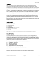
Introduction
Thank-you for purchasing a Klein + Hummel subwoofer. Klein + Hummel’s subwoofers are designed to
compliment Klein + Hummel’s extensive range of monitors. They can be used in music, broadcast, and post
production studios for tracking, mixing, and mastering. They may be positioned next to a wall or flush mounted
into a wall, and can be mixed freely in multichannel systems with other loudspeakers from the Klein + Hummel
range.
The built-in 7.1 Channel High Definition Bass Manager™ is compatible with all formats from mono through to the
latest 7.1 High Definition systems. Eight channels of analog, or an optional 8-channel, 24-bit, 192 kHz digital
input card, ensures flexible interconnectivity for modern studios. Four-mode LFE channel processing ensures
maximum compatibility across all formats. 4th order crossovers and flexible acoustical controls allow for seamless
system integration. Built-in volume control allows for centralized system adjustment independent of the source.
The latest D-class amplifiers and acoustical components have been used to ensure the most accurate sound
reproduction possible. Klein + Hummel products are designed for longevity so we hope you enjoy many happy
years of using this product.
Before reading the rest of this operating manual, review the safety and warnings section towards the back of this
book. Note that imperial dimensions are approximate.
Package Contents
The shipping carton contains:
• This operating manual
• The subwoofer
• Product guarantee
• 3 mains power cables (Euro, UK and USA)
• Trimmer and switch screwdriver
• Angles chart
Signal cables are not included. Options and accessories are listed at the end of this operating manual.
Subwoofer Selection
The recommended subwoofer for a particular system can be found in the document entitled, “K+H Product
Selection Guide”. The latest version can be downloaded from www.klein-hummel.com. In general, one should
ensure that the complete system is balanced and appropriate for a particular application, listening distance, and
room size. Larger main loudspeakers, larger rooms, longer listening distances, multichannel systems, and higher
listening levels each require larger subwoofers. In addition, larger or more subwoofers can be run at lower levels
resulting in lower distortion and a cleaner low frequency reproduction.
The 7.1 High Definition Bass Manager™ is compatible with the following formats:
• 7.1, 7.0 HD (Blu-ray, video gaming)
• 7.1 Theatrical (5 front channels)
• 6.1, 6.0 (DVD, DVD Audio, SACD)
• 5.1, with an additional 2.0 two-channel stereo system
• 5.1, 5.0 (DVD, multichannel CD, HDTV, video gaming)
• 3/1.0 (LCRS)
• 2.0 (two-channel stereo reproduced with or without a subwoofer)
• 1.0 (mono)
Multichannel audio systems with more channels can be constructed using multiple subwoofers.

Klein + Hummel
Operating Manual O 810 / O 870 English 5
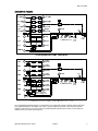
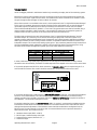
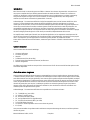
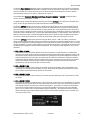
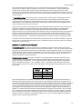
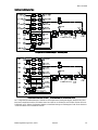
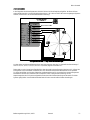
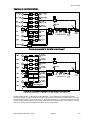
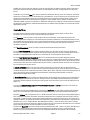
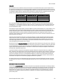
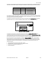
System Block Diagrams
7.1 High Definition Bass Manager™ Block Diagram
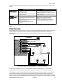
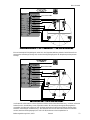
7.1 High Definition Bass Manager™ Block Diagram, with DIM 4 fitted
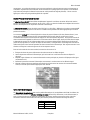
The 7.1 High Definition Bass Manager™ is organized in to an Input Card (analog or digital), Output Card, Filter
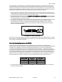
Card, Amplifier Module(s), and Mains Card. There is 1 power amplifier and driver in the O 810 and 2 power
amplifiers and 2 drivers in the O 870. Refer to the detailed product specifications section for information on
amplifier power and driver types (Page 23).

Klein + Hummel
Operating Manual O 810 / O 870 English 6
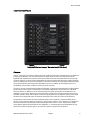
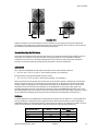
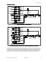
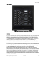
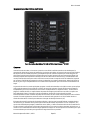
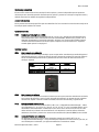
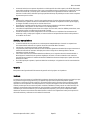
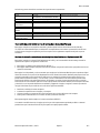
Electronics Panel Picture
7.1 High Definition Bass Manager™ Electronics Panel (O 810 shown)
Crossover
Using 4th order filters, the crossover divides each input signal into two bands for reproduction by the subwoofer
or the main loudspeakers. The crossover frequency is fixed at 80 Hz for all the main channels and can be
bypassed when required. This frequency was chosen to balance the conflicting requirements of having a high
crossover frequency to relieve the main loudspeakers of their low frequency duties thereby reducing distortion,
and of the need to have a low crossover frequency to minimize the chances of localizing the subwoofer thereby
giving greater flexibility when placing the subwoofer in the room. In addition by choosing 80 Hz, there is a
compatibility with the replay conditions commonly found in the home.
The gain for all main channels passing though the subwoofer is 0 dB unless some attenuation has been applied
by the volume control function. The LFE channel is processed independently (see the Filter Card…LFE Mode
section for details). In addition to this an extensive protection system ensures that the loudspeaker is not
damaged if a large signal is applied to the input. The Power On light on the electronics panel flashes when the
protection system is active. If this happens, reduce the input signal level. If this happens regularly, use a larger
subwoofer with a higher SPL output or add more subwoofers to the system to increase the LF headroom.
The protection system consists of: thermal and peak limiters for the amplifier(s), thermal modeling of the
driver(s), and an excursion limiter for the driver(s). The protection system is not a compressor, it is designed to
protect the subwoofer from damage, and the flashing light tells the user it is active. The protection system
cannot protect against sustained abuse of the loudspeaker, i.e. consistently playing the loudspeaker for long
periods of time with the protect light on, so avoid this to ensure a long life from this product.

Klein + Hummel
Operating Manual O 810 / O 870 English 7
Mains Section
The power On/Off switch turns the mains power completely on and off. The applied mains power voltage should
be within -15% and +10% of the selected value. The internal mains fuse value depends on the mains voltage and
is specified on the electronics panel.
The voltage selector switch selects between 220/240 V, and 100/120 V. Set this to the correct value BEFORE
applying mains power to the subwoofer. The internal mains fuse is a suitable value for both voltage settings.
The 12 V trigger is used to turn the subwoofer on and off remotely without having the use the mains power
switch. This may be useful in a large facility where the whole room is powered-up using a single switch.
Equipment can be time-delayed using simple low-voltage circuitry so there is not a mains power surge. Note that
subwoofer’s electronics are fully powered on and off with this control, so the startup time is subject to the same
on/off anti-popping muting delays as if the subwoofer had been turned off and on using the main power switch.
To activate the 12V remote power mode:
• Turn off the subwoofer and disconnect the mains power and signal cables.
• Open the electronics panel (located in the cabinet or remote electronics kit).
• Locate the large switch on the mains power circuit board and move the switch towards the large black
capacitor.
• Close the electronics panel and reattach the mains power and signal cables.
• Power up the subwoofer, apply 12V to the remote control terminals, and check that the appropriate lights are
illuminated.
Analog Input Card
The analog input stages are all 13 kΩ electronically balanced types on female XLR sockets. An input ground lift
switch disconnects pin 1 of all eight input audio grounds from the internal signal ground (note that pin 1 of all
eight input connectors remain connected to each other for both positions of the ground lift switch).
Pin Signal
1 Audio Ground
2 Positive
3 Negative
If there is a humming or buzzing sound coming from the subwoofer(s) or loudspeakers in the system, first check
it is not the subwoofer(s) or loudspeakers by disconnection the input and output signal cables. If the noise goes
away it is not the subwoofer(s) or loudspeakers, so the noises must be coming from the source or source cabling.
There are various ways to increase the loudspeaker’s immunity from these external noises:
• Use the input ground lift switch on the subwoofer(s) and/or loudspeakers to disconnect the audio ground
from the electronics’ chassis ground. For safety reasons, the electronics’ chassis ground is always connected to
the mains power earth pin.
• Use loudspeakers fitted with a transformer balanced input stage. This is especially effective when combined
with the ground lift switch. This is not an option on these subwoofers.

Klein + Hummel
Operating Manual O 810 / O 870 English 8
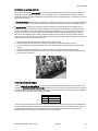
• If unbalanced source signal cables are used, they can be specially wired – see picture below. Disconnect the
cable screen from the RCA sleeve if there are still humming or buzzing sounds, and/or use the ground lift
switch on the loudspeaker. Always use balanced connections from the subwoofer to the main loudspeakers.
Source (RCA) Loudspeaker
(XLR-M)
1
3
2
Unbalanced RCA to Balanced XLR Connections
Signal cable for unbalanced sources
In addition, the 7 main channels are summed and the LFE input has a 0 / +10 dB gain stage. Finally, the test
signal is routed onto the left input for reproduction by the subwoofer and left loudspeaker (see Calibrating Phase
section).
Optional Digital Input Card (DIM 4)
The DIM 4 is an optional card with four 24-bit, 192 kHz digital input stages that can accept AES3-2003
(commonly known as AES/EBU), AES3id-2001, and S/P-DIF (with a suitable connector converter) signals 4 x XLR
and 4 x BNC connectors ensure good interconnectivity options, however only one of the sockets of an input stage
should be used at a time. The DIM 4 card converts up 4 digital audio signals into 8 channels of analog audio,
which are then routed to the channel summers and high pass filters, or the LFE routing and gain stage. Generally
the channel ordering will be as shown in the table below. With the exception of the LFE channel, the seven main
channels may be used for any broadband signal, however the output channel ordering will depend on the input
signal order.
Input Stage Subframe A Subframe B
1 Left Right
2 Center LFE *
3 Surround Left Surround Right
4 Back Left Back Right
* The LFE channel must be placed on AES or BNC input socket 2, subframe B to have access to the appropriate
LFE processing facilities.
Uncompressed PCM AES3, AES3id, and S/P-DIF digital signals generally contain two audio channels (called
“subframe A” and “subframe B”) on one cable (single-wire mode). A clock input is not required because
loudspeakers are not audio sources and the clock signal is locally regenerated from data contained in the bit
stream. Always use good quality cables with the correct impedance and appropriate termination to achieve these
maximum cable lengths:
Format
(Connector) Impedance Cable Length
S/P-DIF (RCA) 75 Ω up to 10 m (30’)
AES3 (XLR) 110 Ω up to 100 m (300’)
AES3id (BNC) 75 Ω up to 1000 m (3000’)
An AES3 signal (applied to an XLR connector) is point-to-point and may not be looped. An AES3id or S/P-DIF
signal can be applied to a BNC connector. The BNC input stage has an internal 75 Ω termination so T-pieces and
terminators are not required. A consequence of this is that it is not recommended to loop the signal to other
equipment using T-pieces. Digital audio errors on any one of the inputs are indicated by a flashing POWER ON
light. If this happens check the cables and connectors, and the source equipment.

Klein + Hummel
Operating Manual O 810 / O 870 English 9
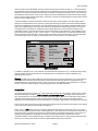
User-bit volume control (IEC 60958-1) may be used for muting input channels: set gain to -∞. Channel soloing is
also possible by muting the other input channels (must be handled by the source). Channel volume control is not
supported. The source must support the IEC 60958-1 standard for muting and soloing to work – see information
provided by the manufacturer of the source to see how it has been implemented. System volume is still possible
by the using the remote control socket (SRC n or RS-232) to control the analog output VOL control blocks without
having to scale the digital signal.
A common problem in television broadcast facilities is audio-video synchronization. The video signal must be
delayed if the video leads the audio, however normally the video lags the audio so the audio should be delayed.
This can be accomplished using the built-in 8-channel digital delay which is located just before the DACs. A time
delay can be applied equally to all eight input channels to compensate for delayed video signals. This facility is
not designed for compensation of loudspeaker time-of-flight differences as this should be inserted at each
loudspeaker output, not at the input channels to the bass manager. The time length of a frame depends on the
picture frame rate frequency: 50 Hz → 40 ms or 60 Hz → 33 ms. The sample rate is automatically detected and
affects the maximum possible delay – higher sample rates lead to a lower maximum delay. The maximum delay
on a 48 kHz signal is 507 ms, which can compensate over 12 x 50 Hz frames or 15 x 60 Hz frames.
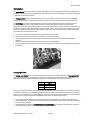
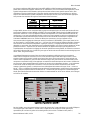
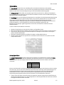
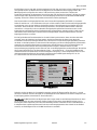
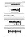
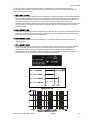
DIM 4 setup software
In addition on the DIM 4, the 7 main channels are summed and the LFE input has a 0 / +10 dB gain stage. Finally,
the test signal is routed onto the left input for reproduction by the subwoofer and left loudspeaker (see
Calibrating Phase section).
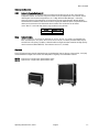
Warning: The digital input option’s BNC connectors protrude from the cabinet’s back panel. The circuit board will
be damaged if the cabinet is placed vertically on a flat hard surface with the driver(s) facing upwards (only
recommended when servicing the driver(s)). Find a soft surface, such as bubble wrap, packing foam, or a folded
blanket, or angle the cabinet slightly to avoid applying pressure to the BNC connectors.
Output Card
The output card has seven channels of 4th order 80 Hz high pass filtering, and a volume control for each of these
channels. Following this, there are 7 x XLR electronic-balanced output stages. All outputs (main channels and
sum) have protection to avoid power on/off noises: the outputs turn on after a short delay when mains power is
applied and mute instantaneously when the mains power is removed. The content of each output channel
depends on the content placed on each of analog inputs, or the optional digital input’s two subframes (channels).
There is also 80 Hz high pass filtering and summing of the LFE channel to the left and right outputs (more details
of how this is used can be found in the Filter Card section).
Finally, there is a Sum output socket for connecting additional subwoofers into the system. There is no volume
control on this output as volume control is performed locally in each subwoofer. As the output is a filtered sum of
the input channels, it should be connected to the LFE/Sum input on subsequent subwoofers in the system (see
example system diagrams in the System Use section). These should have their LFE mode switch set to
“SUB ONLY (WIDE)” so that double filtering is not applied. As the Sum output is always analog, subwoofers after
the first one in a daisy chain should not have the optional DIM 4 digital input card fitted.
Loudspeaker Level System Delay
Left 00.0 dB Delay 200.0 ms
Center 00.0 dB Sample Rate 48 kHz
Right 00.0 dB Frame Rate Frequency 50 Hz
Left Surround 00.0 dB Delay per frame 20.0 ms
Right Surround 00.0 dB Frames 10.0
Left Back 00.0 dB
Right Back 00.0 dB Communication Port
Subwoofer 00.0 dB
K+H DIM 4 Set-up
Upload New Settings
X
COM 1 ▼
Read Current Settings

Klein + Hummel
Operating Manual O 810 / O 870 English 10
Filter Card
The filter card contains bass management processing, subwoofer filtering, acoustical controls and a remote
control input socket:
The Power On light (red) is illuminated when power is applied to the subwoofer, the mains power switch is on,
and the 12 V DC remote control are in a state to turn on the subwoofer. This light blinks during the power-up
phase of the internal microcontroller, and flashes if the protection system is activated. If the latter happens, turn
down the input signal, use a bigger subwoofer, or add additional subwoofer(s) to the system.
The Bass Management light (green) is illuminated when bass management is on.
The Bass Management switch turns on the bass management. This inserts a 4th order 80 Hz high pass filter into
the signal path of each main channel output and routes content below 80 Hz to the subwoofer. Reproduction of
the LFE channel is unaffected by the setting of this bass management switch.
The Rear Channel Bass Management switch define whether the rear channels (left surround, right surround, left
back and right back) are included in the bass management processing. Some sound engineers prefer to bass
manage the rear channels, others do not. The use of this switch avoids having to unplug the XLR connectors for
these channels. Reproduction of the LFE channel is unaffected by the setting of this bass management switch.
The Volume Control switch defines whether the remote volume control facility is activated or not. There is no
attenuation of the input signals when the remote volume control is deactivated, so care should be taken when
adjusting this switch. If a remote control device (SRC 1, SRC 2, or RS-232) is disconnected from the subwoofer,
remote volume control is automatically disabled (gain through the bass management defaults to 0 dB).
The Signal Generator switch applies an 80 Hz sine wave signal to the left channel input (on the DIM 4 it is digital
input 1, subframe A). This low frequency tone will be audible through the subwoofer and the loudspeaker
connected to the left output socket. It is used for setting the phase control (see Calibrating Phase section).
The Subwoofer Gain, Subwoofer Phase, Parametric Equalizer, and Low Cut controls are described in the Acoustical
Controls section below.
LFE channel reproduction depends on the LFE mode settings (see LFE Mode description below) and is unaffected
by the setting of either of the bass management switches.
The LFE Gain switch applies 0 or +10 dB gain to the LFE channel. For Dolby Digital and DTS formats only, one
10 dB boost is required in the monitoring system somewhere between the LFE channel fader on the mixing
console and the listener’s ear. This boost can be performed in the monitoring matrix (console or external), in a
decoder output stage (surround sound processor or DVD/Blue-ray disk player), or in the 7.1 High Definition Bass
Management System™. Before using this switch, check that it has not been applied somewhere else in the signal
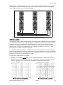
path. Too much LFE channel gain results in less LFE channel level in the mix, and vice versa.
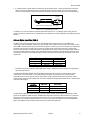
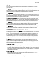
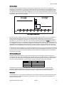
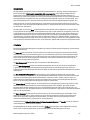
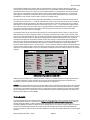
The LFE Mode switch has four settings (the default is LFE → SUB + L/R (>80)) designed to process the LFE
channel in different ways for different system configurations and source equipment. The LFE channel must be
applied to the dedicated LFE input channel for this processing to work (“LFE” on the analog input card, or
input 2, subframe B on the digital input card). Reproduction of the LFE channel is unaffected by the setting of the
bass management switches. The modes and their use are:
1. LFE → SUB + L/R (>80)
Up to 80 Hz, the LFE channel is reproduced by the subwoofer. Above 80 Hz, the LFE channel is re-routed to the
left and right outputs. A 6 dB electrical attenuation is applied to compensate for a 6 dB acoustical gain seen
when reproducing one signal using two loudspeakers. This mode works with all formats and is consistent with
the standard downmix coefficients seen in consumer decoders. Additionally, this mode is useful for detecting
higher frequency signals (up to the upper cut-off frequency of the left/right loudspeakers) in the LFE channel
that should otherwise be avoided.
2. LFE → SUB ONLY (<80)
The LFE channel is reproduced up to 80 Hz in the subwoofer only. This comes from a recommendation by
Dolby and THX to “pre-filter” the LFE channel and is used to simulate consumer decoders that do not
reproduce the upper part of the LFE bandwidth.

Klein + Hummel
Operating Manual O 810 / O 870 English 11
3. LFE → SUB ONLY (<120)
The LFE channel is reproduced up to 120 Hz in the subwoofer only. This is the norm for the movie industry.
4. LFE → SUB ONLY (WIDE)
The LFE channel is reproduced by the subwoofer only. There is no filtering of the LFE channel. This is an
appropriate setting when the input comes from the Sum output of another K+H subwoofer, or from
equipment with its own bass management, such a surround sound processor or DVD/Blue-ray disk player
(usually the “Subwoofer” output). Additionally, this mode is useful for detecting higher frequency signals
(up to 300 Hz) in the LFE channel that should otherwise be avoided.
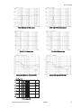
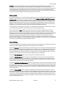
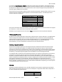
LFE Channel Mode Settings
LFE Channel Electrical Response
The Remote Control and RS-232 EtherCon connector is used to connect hardware or RS-232 remote controlers to
the subwoofer. No audio passes down the CAT5 type cable, only control signals. The CAT-5 cable should not be
plugged into an IP or network output socket otherwise damage may occur to the source equipment. Furthermore,
the CAT cable should not carry an IP signal.

Klein + Hummel
Operating Manual O 810 / O 870 English 12
Two hardware remote controls (SRC 1 and SRC 2) are available from Klein + Hummel together with various
lengths of high-quality CAT-5 cable with EtherCon connectors (RC nn). The signals on the cable are as follows:
Remote Control Function RJ-45 Pins
Volume Control 1
LOGO Voltage 2
GND * 3
RS 232 TX * 4
RS 232 RX * 5
Supply Voltage +3.3 V 6
Bypass Bass Management 7
+10 dB LFE Gain 8
For connection options see Volume Control section. A * indicates RS-232 data connections.
Finally, there is a VOL stage to control the output level of the subwoofer.
Amplifier Module(s)
The O 810 has one amplifier module. The O 870 has two amplifier modules – one for each driver. The amplifier(s)
use D-class technology to minimize heat dissipation and are run in bridged mode to minimize distortion. Even so
some space (5 cm, 2”) is required around the electronics panel. In other technical aspects, such as harmonic
distortion, intermodulation distortion, and noise, the performance is as good class AB designs.
Driver(s) and Acoustical Response
The driver(s) are the best available for their application. Long throw, efficient, low distortion drivers ensure a
clean sound quality even at high replay levels. The driver(s) is/are loaded by the internal volume of the cabinet
and is/are magnetically shielded for use next to CRT screens and magnetic storage media. The system’s
SPL output and the cabinet volume can be seen in the Specifications section below.
Klein + Hummel subwoofers are designed to have a flat pass band magnitude response in anechoic conditions
when all the acoustical controls are set to 0 dB. When a subwoofer is installed into a listening environment the
response changes and thus should be corrected back to a flat response. It is therefore expected that the
acoustical controls will need adjustment to improve the in-situ response of the subwoofer. The acoustical
controls’ settings depend on the subwoofer’s location and will probably be different for the same subwoofer type
installed in different locations in the same room. Moving the cabinet small distances, 50 cm (20”), can
dramatically change the response therefore resulting in different acoustical control settings.
Cabinet
The wooden cabinet is painted using a standard RAL color. An appropriately colored pen can be used to touch up
the paintwork if it is scratched during transport or use. The following RAL numbers correspond to K+H standard
cabinet colors.
K+H Color Name RAL Number
Anthracite 7021
Silver 9006
Rubber feet reduce the risk of scratching the cabinet and provide some mechanical isolation from the floor.
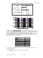
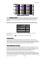
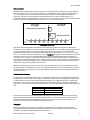
The acoustical axis is a line normal to the subwoofer’s front panel along which the microphone was placed when
tuning the subwoofer’s crossover during design. For subwoofers in the Klein + Hummel range, the acoustical axis
is located on the mid-point of the driver(s).
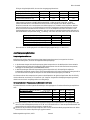
Product x dimension y dimension
O 810 16.5 cm (6 1/2“) 17.0 cm (7 1/2“)
O 870 16.5 cm (6 1/2“) 36.0 cm (14 1/8“)

Klein + Hummel
Operating Manual O 810 / O 870 English 13
Acoustical Axis
However, subwoofer’s can be considered to be omni-directional in their typical pass band as the generated
wavelength is long compared to the object producing the sound, therefore it does not matter in which direction
the subwoofer is pointing when placed in the listening environment.
Remote Mounting the Electronics
As the electronics back panel does not seal the enclosure, it can be remote mounted using the REK 2 and SC nn
accessories. If the cabinet is to be flush mounted, care should be taken to ensure that there is adequate
ventilation for the electronics. Although no damage will result, insufficient cooling will cause the amplifier
protection to activate prematurely thereby limiting the system’s maximum output level.
System Use
Klein + Hummel loudspeakers should only be used indoors and in these ambient conditions:
• +10° C to +40° C (+50° F to +104° F), <90% relative humidity, non-condensing
During transport or storage the ambient conditions can be:
• -25° C to +70° C (-13° F to 158° F), <90% relative humidity, non-condensing
Before connecting the mains power cable, ensure that the correct mains voltage is indicated on the electronics
panel (220-240V or 100-120 V) and that the mains power switch is off. Next connect the input signal cables
(analog or digital as appropriate) and output cables, then power up the loudspeaker. There is a three second
delay before sound can be heard from subwoofer(s) and loudspeakers so as to avoid noises (pops) from
preceding equipment turned on at the same time. During this period the POWER ON light flashes, then it turns
solid indicating that audio can be heard. If there are no lights, check the mains power supply. Conversely, turning
off the subwoofer immediately mutes the audio from the subwoofer and loudspeakers connected to it.
Positioning
In a studio application, the loudspeakers should be placed according to the ITU-R BS.775-1 recommendations so
there is consistency of reproduction when compared to other listening environments. For movie applications,
ANSI/SMPTE 202M is the preferred standard for system setup. For home use, as materials are mixed in ITU style
rooms, one should get as close as possible to this configuration to maximize replay authenticity.
Loudspeaker Name ITU-R BS.775-1 Angle ANSI/SMPTE 202M
Angle
Left -30° -22.5°
Center 0° 0°
Right 30° 22.5°
Left Surround -110°±10° An array to the left
Right Surround 110°±10° An array to the right

Klein + Hummel
Operating Manual O 810 / O 870 English 14
For two-channel stereo, ±30° should be used. There are currently no internationally agreed standards for 6.1 or
7.1 formats. However common practice is to use one or two loudspeakers in the centre back location of a
6.1 system. In a 7.1 system common practice is to place side loudspeakers at ±90° and to push the surround
loudspeakers back to ±150°.
For the best stereo imaging the loudspeakers should be placed symmetrical in a symmetrical room where objects
have been placed symmetrically. This ensures the same response from each loudspeaker at the listening position
and thus good imaging. Sound reflected back to the listening position should also be minimized using surface
angling or acoustical treatment. The acoustical axis should point towards the listening position or centre of the
listening area in both the horizontal and vertical planes.
The loudspeakers should be placed on a circle to ensure equal time of arrival of the audio from all loudspeakers.
Failing this, appropriate electronic time delays should be added between the subwoofer and each loudspeaker to
compensate for time of flight differences. This can either be a Pro C 28 inserted into the signal chain before the
loudspeaker, or a Pro C 28 attached to the power amplifier direct input on an O 300 D.
An angles chart has been included in the package to help position the loudspeakers at the correct angle. Simple
locate the center of the angles chart at the listening position, and then use a XLR cable or piece of string
stretched tightly between the center of the angles chart and the acoustical axis of each loudspeaker to ensure
that each loudspeaker is positioned at the correct angle. A document defining the acoustical axis of
K+H loudspeakers can be found at www.klien-hummel.com.
Ports located on the front panel all allows Klein + Hummel loudspeakers and subwoofers to be easily flush
mounted. The principle benefits are that it gets the cabinet out of the room (less space taken up in the room),
increased driver loading (reduced distortion), and elimination of rear wall cancellations (smoother response). It is
a good idea to employ an experienced acoustic engineer to design an effective flush mounting wall. If the
loudspeakers and subwoofers must be covered, use a thin open weave cloth. Two layers of very thin material will
improve opacity.
The 80 Hz crossover is low enough to give good flexibility when placing the subwoofer(s) in the room. Placement
depends on whether one or multiple subwoofers are used (see next section).
Single and Multiple Subwoofer Systems
One subwoofer can be used in a system if space or budget is limited. However, it should be checked that the
output capacity is sufficient to match the main loudspeakers otherwise the subwoofer will be the limiting
component in the system. Please refer to the “Product Selection Guide” for building balanced systems. In a single
subwoofer system, the subwoofer should be located against the front wall, and positioned slightly left or right of
the middle of the front wall. Calibration and positional adjustments can be made from this starting point.
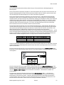
Multiple subwoofers can be used in a system to increase the low frequency SPL capacity of the system. Mutual
coupling between subwoofers occurs when they are placed within a quarter-wavelength of each other. This is
approximately 1 m (3’) for frequencies up to 80 Hz. If the LFE mode is set to “LFE → SUB ONLY (<120)”, the
subwoofer spacing should be reduced to less than 70 cm (2.5’). The acoustical gain when mutual coupling occurs
is shown in the table below:
Number of
Subwoofers Acoustical Gain
[dB]
1 0.0
2 6.0
3 9.5
4 12.0
An additional benefit of multiple subwoofer systems is the possibility to reduce the side wall interaction thereby
improving the side-to-side low frequency reproduction. This is important in studio applications where the sound
engineer needs to move left and right along the mixing console, or where there are multiple listening positions
along a large format mixing consol, for example in the movie industry. The subwoofer should be positioned along
the front wall to generate a plane wave down the room. This is called a “Plane Wave Bass Array™” (PWBA™). The
required number of subwoofers depends on the width of the room: wider rooms, more subwoofers. Two to four
are recommended for small rooms and three to four for larger rooms. The subwoofers should be positioned along
the front wall with a suitable spacing (see comments above) to generate a plane wave down the room. Please
refer to the “Product Selection Guide” for suggest system solutions.

Klein + Hummel
Operating Manual O 810 / O 870 English 15
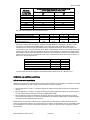
A summary of the advantages and disadvantages of a single and multiple subwoofer systems is shown in the
table below:
Advantages Disadvantages
Single subwoofer
systems Lower cost
Less total space required
Might be easier to setup
Consistent acoustic summing in the
listening area
One large cabinet may be hard to position
No suppression of side wall interactions
No suppression of room resonances
Multiple subwoofer
systems Multiple smaller cabinets may be easier to
position in the room
Suppression of side wall interactions
(PWBA™)
Suppression of room resonances (PWBA™)
Higher cost
More total space required
Might be harder to set up
Possible inconsistent acoustical summing in
the listening area
See the Volume Control section for details on how to control multiple subwoofer systems.
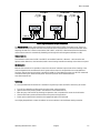
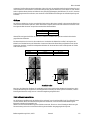
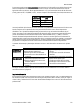
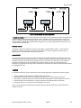
Interconnection Examples
In the following interconnection diagrams, O 300 and O 810 have been shown as examples. Other products from
the Klein + Hummel range can be substituted, for example O 410 and O 870. Please refer to the “K+H Product
Selection Guide” for building balanced systems.
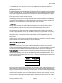
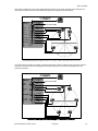
Analog connections to the 7.1 High Definition Bass Manager™
From the above wiring diagram it is easy to see that the 7.1 High Definition Bass Manager™ can also be used for
1.0, 2.0, 3/1.0, 5.0, 5.1, 6.0, 6.1, and 7.1 (theatrical) signals.
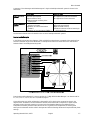
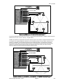
A less obvious but very useful configuration is also possible. A 5.1 signal can be connected as shown in the
diagram below. In addition, the two unused back channels can be connected to a separate 2.0 signal and the
subwoofer used to give bass extension to a second pair of loudspeakers. Note that the additional pair of
loudspeakers should be placed the same distance as the 5.1 system’s main loudspeakers so that the phase
setting on the subwoofer remains valid for both systems. Different listening distances will require different phase
settings.

Klein + Hummel
Operating Manual O 810 / O 870 English 16
Simultaneous connection of 5.1 and 2.0 signals to the 7.1 High Definition Bass Manager™
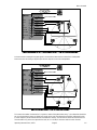
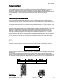
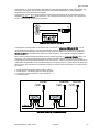
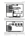
An interconnection example for digital signals is shown below. Note that the subwoofer-to-loudspeaker
interconnections are analog so digital inputs are not required on the main loudspeakers.
Digital connections to the 7.1 High Definition Bass Manager™
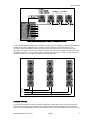
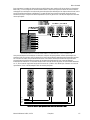
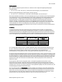
To increase the number of subwoofers in a system to make a Plane Wave Bass Array™, the subwoofers should be
set up as shown below. Analog or digital input cards can be used. The subwoofers should be calibrated for their
in-room response (see Acoustical Controls and Calibration section). The LFE channel should be connected to the
first subwoofer only so that the reproduction level (at 0 or +10 dB) is consistent with the main channels.

Klein + Hummel
Operating Manual O 810 / O 870 English 17
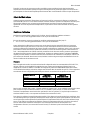
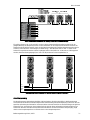
Connecting multiple subwoofers to make a Plane Wave Bass Array™
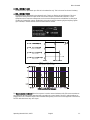
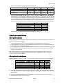
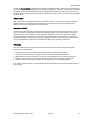
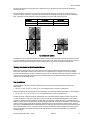
A 4-way column loudspeaker installation is possible for large systems, for example O 410 and O 870. Hardware is
available for the main loudspeaker to be mounted on top of the subwoofer with a tilting function. The
subwoofers should be calibrated so that they smoothly extend the bass response of their respective main
loudspeaker (see Acoustical Controls and Calibration section). The LFE channel should be connected to all of the
subwoofers, using XLR “Y” cables, and the signal level adjusted at the source by -9.5 dB or +0.5 dB so that the
reproduction level (at 0 or +10 dB) is consistent with the main channels.
Left
Right
Center
LFE
Large system mounting to make a 4-way column system
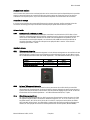
Acoustical Controls
The acoustical controls are low-order analog filters designed to compensate for some of the acoustical issues
commonly found in listening environments. The acoustical controls’ settings will depend on the subwoofer’s
location and will probably be different for the same subwoofer type positioned in different locations in the same

Klein + Hummel
Operating Manual O 810 / O 870 English 18
room. When calibrating subwoofers there are three areas requiring attention: in-room response, level relative the
main loudspeakers, and phase relative to main loudspeakers.
For systems containing subwoofers, it is highly recommended to use an acoustical measurement system to set
the acoustical controls (gain, parametric and low cut filters, and phase) in the most appropriate way to
compensate for the subwoofer’s location. This is especially true of the parametric equalizer’s controls which are
very hard to set by listening.
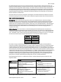
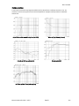
The acoustical control set consists of the following:
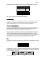
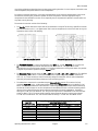
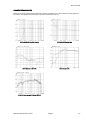
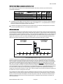
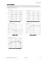
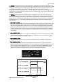
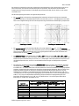
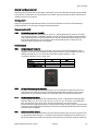
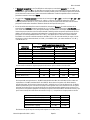
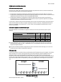
• The Low Cut control reduces the output level of the subwoofer in ranges of 30 Hz using a peak filter centered
on 30 Hz and with a Q of 1.5 – see graph below. This is used to compensate for a rise in level seen at very low
frequencies due to a lack of LF damping.
Low Cut acoustical control Parametric Equalizer acoustical controls
• The Parametric Equalizer is a single stage PEQ filter with gain (+4…-12 dB), frequency (20…120 Hz) and
Q (1…8) controls designed to control nonlinearities seen below 120 Hz – see graph above. These
nonlinearities can come from boosts caused by constructive interference or strong room modes. It is possible
to bypass the parametric equalizer using the bypass switch.
• The Subwoofer Phase controls consist of a 0° / -180° switch and 0° / -45° / -90° / -135° switch. This applies a
very short delay (45° at 80 Hz = 1.56 ms) to the subwoofer output, and gives a positional resolution of
0.54 m (1’ 9”). These controls are used to acoustically realign the subwoofer with the main loudspeakers
when they are positioned at different distances from the listening position.
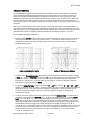
• The subwoofer’s output level is controlled using the Subwoofer Gain controls. This consist of a finely
graduated Input Gain (+2 to -12 dB) potentiometer and a coarse Output Level (100 or 114 dB SPL at 1 m)
switch. This allows the subwoofer to be matched to a wide range of equipment outputs whilst maintaining
the desired acoustical output. It can also compensate for level differences due to acoustical loading and the
distance of the subwoofer from the listening position compared to the main loudspeakers. The default
settings are “0 dB” and “100 dB SPL at 1m”. This gives an output level of 100 dB SPL at 1m when the input
signal is 0 dBu (0.775 V). The most sensitive setting (most acoustical output for a given input voltage)
is “2 dB” and “114 dB SPL at 1m”, and the least sensitive setting is “-12 dB” and “100 dB SPL at 1m”.
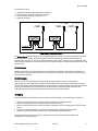
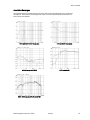
Acoustic output level [dB SPL] of the loudspeaker at 1m
when input signal is 0 dBu
Input Gain
Potentiometer [dB] Output Level switch = “100 dB” Output Level switch = “114 dB”
-12 dB 88 102
-10 dB 90 104
-8 dB 92 106
-6 dB 94 108
-4 dB 96 110
-2 dB 98 112
0 dB 100 (default) 114
2 dB 102 116
Seite wird geladen ...
Seite wird geladen ...
Seite wird geladen ...
Seite wird geladen ...
Seite wird geladen ...
Seite wird geladen ...
Seite wird geladen ...
Seite wird geladen ...
Seite wird geladen ...
Seite wird geladen ...
Seite wird geladen ...
Seite wird geladen ...
Seite wird geladen ...
Seite wird geladen ...
Seite wird geladen ...
Seite wird geladen ...
Seite wird geladen ...
Seite wird geladen ...
Seite wird geladen ...
Seite wird geladen ...
Seite wird geladen ...
Seite wird geladen ...
Seite wird geladen ...
Seite wird geladen ...
Seite wird geladen ...
Seite wird geladen ...
Seite wird geladen ...
Seite wird geladen ...
Seite wird geladen ...
Seite wird geladen ...
Seite wird geladen ...
Seite wird geladen ...
Seite wird geladen ...
Seite wird geladen ...
Seite wird geladen ...
Seite wird geladen ...
Seite wird geladen ...
Seite wird geladen ...
Seite wird geladen ...
Seite wird geladen ...
Seite wird geladen ...
Seite wird geladen ...
Seite wird geladen ...
Seite wird geladen ...
Seite wird geladen ...
Seite wird geladen ...
Seite wird geladen ...
Seite wird geladen ...
Seite wird geladen ...
Seite wird geladen ...
Seite wird geladen ...
Seite wird geladen ...
Seite wird geladen ...
Seite wird geladen ...
Seite wird geladen ...
Seite wird geladen ...
Seite wird geladen ...
Seite wird geladen ...
Seite wird geladen ...
Seite wird geladen ...
Seite wird geladen ...
Seite wird geladen ...
Seite wird geladen ...
Seite wird geladen ...
Seite wird geladen ...
Seite wird geladen ...
Seite wird geladen ...
Seite wird geladen ...
Seite wird geladen ...
Seite wird geladen ...
Seite wird geladen ...
Seite wird geladen ...
Seite wird geladen ...
Seite wird geladen ...
Seite wird geladen ...
Seite wird geladen ...
Seite wird geladen ...
Seite wird geladen ...
Seite wird geladen ...
Seite wird geladen ...
Seite wird geladen ...
Seite wird geladen ...
Seite wird geladen ...
Seite wird geladen ...
Seite wird geladen ...
Seite wird geladen ...
Seite wird geladen ...
Seite wird geladen ...
Seite wird geladen ...
Seite wird geladen ...
Seite wird geladen ...
Seite wird geladen ...
Seite wird geladen ...
Seite wird geladen ...
Seite wird geladen ...
Seite wird geladen ...
Seite wird geladen ...
Seite wird geladen ...
-
 1
1
-
 2
2
-
 3
3
-
 4
4
-
 5
5
-
 6
6
-
 7
7
-
 8
8
-
 9
9
-
 10
10
-
 11
11
-
 12
12
-
 13
13
-
 14
14
-
 15
15
-
 16
16
-
 17
17
-
 18
18
-
 19
19
-
 20
20
-
 21
21
-
 22
22
-
 23
23
-
 24
24
-
 25
25
-
 26
26
-
 27
27
-
 28
28
-
 29
29
-
 30
30
-
 31
31
-
 32
32
-
 33
33
-
 34
34
-
 35
35
-
 36
36
-
 37
37
-
 38
38
-
 39
39
-
 40
40
-
 41
41
-
 42
42
-
 43
43
-
 44
44
-
 45
45
-
 46
46
-
 47
47
-
 48
48
-
 49
49
-
 50
50
-
 51
51
-
 52
52
-
 53
53
-
 54
54
-
 55
55
-
 56
56
-
 57
57
-
 58
58
-
 59
59
-
 60
60
-
 61
61
-
 62
62
-
 63
63
-
 64
64
-
 65
65
-
 66
66
-
 67
67
-
 68
68
-
 69
69
-
 70
70
-
 71
71
-
 72
72
-
 73
73
-
 74
74
-
 75
75
-
 76
76
-
 77
77
-
 78
78
-
 79
79
-
 80
80
-
 81
81
-
 82
82
-
 83
83
-
 84
84
-
 85
85
-
 86
86
-
 87
87
-
 88
88
-
 89
89
-
 90
90
-
 91
91
-
 92
92
-
 93
93
-
 94
94
-
 95
95
-
 96
96
-
 97
97
-
 98
98
-
 99
99
-
 100
100
-
 101
101
-
 102
102
-
 103
103
-
 104
104
-
 105
105
-
 106
106
-
 107
107
-
 108
108
-
 109
109
-
 110
110
-
 111
111
-
 112
112
-
 113
113
-
 114
114
-
 115
115
-
 116
116
-
 117
117
-
 118
118


in anderen Sprachen
Andere Dokumente
-
Neumann KH 870 Benutzerhandbuch
-
CABASSE Santorin 38 Bedienungsanleitung
-
-
Focal Astral 16 Benutzerhandbuch
-
Elac TX2040 Bedienungsanleitung
-
XTZ Spirit SUB 12 Bedienungsanleitung
-
Polk Audio RT3000P Bedienungsanleitung
-
Dynaudio Contour SUB Benutzerhandbuch
-
Arcam AV8 Benutzerhandbuch