Ingo Maurer Lacrime del Pescatore Bedienungsanleitung
- Typ
- Bedienungsanleitung

Lacrime del Pescatore Instructions

3
Montageanleitung
Bitte vor der Montage aufmerksam lesen und auf-
bewahren!
Instructions for assembly
Please read these instructions carefully before going
any further, and keep them in a safe place for future
reference!
Instructions de montage
À lire attentivement avant le montage et à conser-
ver!
Istruzioni di montaggio
Prima del montaggio, leggere attentamente le
istruzioni e conservarle!
Deutsch Seite 4
English Page 8
Français Page 12
Italiano Pagina 16
Zeichnungen Seite 20
Drawings Page 20
Dessins Page 20
Disegni Pagina 20

5
Deutsch
4
Deutsch
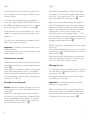
Lacrime del Pescatore kann in jeder erdenklichen Art und
Weise an Decken und/oder Wänden aufgehängt oder abge-
spannt werden. Ihren vielfältigen Gestaltungsmöglichkeiten
sind kaum Grenzen gesetzt.
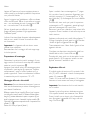
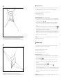
Nachfolgend wird die Deckeninstallation für Raumhöhen
von 250 bis max. 350 cm beschrieben. Das unterste Netz
hängt in diesem Fall – bei einem Abstand der Aufhänge-
punkte von 200 cm – ca. 75 cm unter der Decke. ①
Bei großen Räumen mit hohen Decken und/oder der
Abspannung von Wänden verweisen wir auf das Beiblatt
“Sonderinstallationen”.
Die Lichtquelle wird unabhängig von den Kristallnetzen an
der Wand befestigt: ein Deckenauslass ist nicht notwedig.
Wichtig: Montage und Elektroanschluss müssen von
einer Elektrofachkraft ausgeführt werden.
Wir empfehlen, die Montage der Netze mit zwei
Personen durchzuführen.
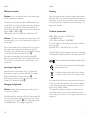
Montagevorbereitung
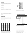
Legen Sie die Position der Aufhängepunkte fest. Beachten
Sie hierbei, dass die Netze rautenförmig zwischen den
Aufhängepunkten hängen. ②
Benutzen Sie beiliegende Klebepunkte, um die vier Aufhänge-
punkte zunächst am Boden zu markieren. Übertragen Sie
die Punkte dann mittels Senklot oder Laser an die Decke.
Beachten Sie die unterschiedlichen Kennzeichnungen der
Aufhängepunkte: „A“ und „B“.
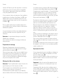
Montage der Netze und der Kristalle
Wichtig: Achten Sie unbedingt auf den Verlauf von
Elektroleitungen, damit auf keinen Fall ein Kabel angebohrt
wird.
Bohren Sie die vier Dübellöcher Ø 6 mm für die Netz-
abhängungen und setzen Sie die Dübel S6 ein.
Drehen Sie die vier Seilabhängungen (8) mit Hilfe des
beiliegenden Inbusschlüssels (9) fest in die Dübel ein und
verwenden Sie falls notwendig die mitgelieferten Beilag-
scheiben (10). Jede Abhängung besteht aus drei Spann-
seilen mit Häkchen (11). ③
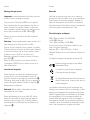
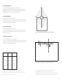
Beginnen Sie mit dem kleinsten Netz (Tüte 1). Öffnen
Sie die mit „1“ gekennzeichneten Seilspulen durch Knicken
und rollen Sie das Aufhängeseil ab. Hängen Sie die Häkchen
(11) an den Aufhängepunkten „A” in die mit einer weißen
Schlaufe (12) gekennzeichneten Netzecken (13) ein. ④
Verfahren Sie genauso mit den Seilabhängungen der Auf-
hängepunkte „B“ und hängen Sie die Häkchen in die mit
einer schwarzen Schlaufe gekennzeichneten Netzecken.
Entfernen Sie die schwarzen und weißen Markierungs-
schlaufen und die Klebestreifen an den Seilabhängungen.
Legen Sie das Päckchen mit dem Salz in das Netz, um es
zu beschweren.
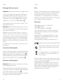
Bestücken Sie das kleine Netz mit den Kristallen aus der
mit „1“ gekennzeichneten Verpackung. Bitte verwenden Sie
hierfür die beiliegenden Stoffhandschuhe. Nehmen Sie die
Kristalle am Haken aus der Verpackung und hängen Sie sie
im Netz ein. Ziehen Sie die Haken vorsichtig nach unten,
bis sie im Netz einrasten.⑤
Wir empfehlen eine unregelmäßige Verteilung der Kristalle
mit kleineren Abständen zur Netzmitte hin. ⑥
Verfahren Sie ebenso mit dem mittleren und dem großen
Netz (Tüten 2 und 3). Sobald alle Kristalle eingehängt
sind, entfernen Sie bitte das Salzpäckchen.
Einstellen der Netze
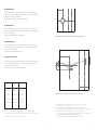
Sie können die Seilspannung nachjustieren, indem Sie das
Röhrchen (15) auf dem Seil verschieben und gleichzeitig
das Restseil nachlassen oder nachziehen. ⑦
Durch Anziehen der Seile werden die Netze gestrafft;
durch Nachlassen der Seile lässt die Spannung nach und
die Form wird bauchiger.
Wichtig: Achten Sie darauf, dass sich die untereinander
hängenden Netze beim Straffen nicht berühren.
Hängen die Netze in der gewünschten Position, kürzen Sie
das überschüssige Seil bis auf eine Länge von ca. 30 cm.
Befestigen Sie den Kristall mit einem Doppelknoten am
Seilende. Legen Sie dann die Restseile an den Netzkanten
entlang auf dem Netz ab. ⑧

Montage des Wandspots
Wichtig: Stecken Sie den Netzstecker erst nach abge-
schlossener Montage in die Steckdose.
Der Wandspot sollte 100 cm unterhalb der Decke befestigt
werden. Bei niedrigen Decken muss die Lichtquelle über
Augenhöhe liegen, um Blendung zu vermeiden. Die optimale
Entfernung des Wandspots zur Mitte der Kristallnetze beträgt
ca. 200 - 400 cm. ①
Markieren Sie das Bohrloch für die Befestigung des
Trafogehäuses (17).
Achtung: Achten Sie unbedingt auf den Verlauf von
Elektroleitungen, damit auf keinen Fall ein Kabel angebohrt
wird.
Bohren Sie ein Dübelloch Ø 6 mm und setzen Sie den
Dübel S6 ein. Öffnen Sie das Gehäuse mit dem beilie-
genden Inbusschlüssel. Lösen Sie den Gehäusedeckel (18)
und schrauben Sie das Trafogehäuse mit beiliegender
Schraube (19) an die Wand. ⑨
Schließen Sie den Deckel wieder und ziehen Sie beide
Inbusschrauben (20) fest. Entfernen Sie die Schutzfolie
vom Gehäusedeckel. Der Ein-/Ausschalter des Wandspots
befindet sich am Netzkabel.
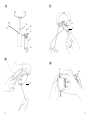
Einsetzen des Leuchtmittels
Setzen Sie das Leuchtmittel ein, indem Sie den Haltebügel
(21) an den Enden zusammendrücken und an der Rückseite
des Leuchtmittels einrasten lassen. ⑩
Schieben Sie die beiden Kabelschuhe (22) bis zum
Anschlag auf die Kontaktlaschen (23) an der Rückseite des
Leuchtmittels. ⑪
Wechsel des Leuchtmittels
Achtung: Ziehen Sie den Netzstecker und lassen Sie die
Lampe vollständig abkühlen.
Ziehen Sie vorsichtig die Kabelschuhe (22) von den Kontakt-
laschen (23) ab und entfernen Sie das defekte Leuchtmittel,
indem Sie den rückseitigen Haltebügel (21) zusammen-
drücken. ⑫ Setzen Sie das neue Leuchtmittel ein wie
unter “Einsetzen des Leuchtmittels” beschrieben.
7
6
Deutsch
Pflege
Besprühen Sie die Kristalle mit handelsüblichem Glasreiniger
und polieren Sie sie mit einem weichen fusselfreien Tuch.
Um an die oberen beiden Netze zu gelangen, lösen Sie
gegebenenfalls die Verbindungsseile zum unteren Netz.
Haken Sie dann das unterste Netz an zwei nebeneinan-
der liegenden Ecken aus und lassen Sie es senkrecht nach
unten hängen.
Technische Daten
230V~ 50Hz., sekundär 12V 3-55W LED
oder 20-100W Halogen
125V~ 60Hz. sekundär 12V 20-100W,
Die für Ihre Leuchte zutreffende Spannung und Frequenz ent-
nehmen Sie bitte dem Typenschild.
Leuchtmittel AR111, Sockel G53, Spot 6-12 Grad
Dimmbar (abhängig vom Leuchtmittel, Dimmer nicht ent-
halten)
Diese Leuchte ist geeignet für Leuchtmittel der
Energieklassen A-G .
Mindestabstand zu brennbaren Flächen: 70 cm
Dieses Symbol weist darauf hin, dass zwingend
ein “self-shielded” Leuchtmittel verwendet wer-
den muss.
Eine defekte Leuchte muss als Elektroschrott
entsorgt werden und darf nicht in den Hausmüll
gelangen.
Eventuell notwendige Reparaturen dürfen nur von einer
Elektrofachkraft durchgeführt werden. Die äußere Leitung
darf bei Beschädigung nur von der Ingo Maurer GmbH
ausgetauscht werden.
Bei Schäden, die durch Nichtbeachten dieser
Bedienungsanleitung, unsachgemäßer Inbetriebnahme und/
oder baulicher Veränderung z.B. durch Fremdbauteile,
Handhabung oder Fremdeingriff verursacht werden,
erlischt der Garantieanspruch.
Deutsch

Lacrime del Pescatore can be mounted in a multitude of
ways on ceilings or walls: the range of installation options
is almost unlimited.
The following instructions are for ceiling installations in
rooms with a height of 250 to 350 cm, with a distance of
about 200 cm between the suspension points, so that the
bottom net hangs about 75 cm below the ceiling. ①
See the separate sheet “Special installations” for notes on
installation in large spaces with high ceilings and/or wall
installation.
The light source is wall-mounted and separate from the
nets: a ceiling outlet is not required.
Important: All electrical work must be carried out by a
qualified electrician.
We recommend that a second person be present to help
with the assembly of the nets.
Preparations for assembly
Determine the position of the suspension points, bearing
in mind that the nets hang in a lozenge shape between the
fixtures. ②
Use the adhesive dots supplied to mark the four suspension
points, with the lamp resting on the floor. The markings
can then be transferred to the ceiling with a plumb-line or
laser pointer, bearing in mind the distinction between sus-
pension points “A“and “B“.
Assembly of nets and crystals
Caution: Take care to ascertain the exact position of all
electrical wiring, so as to avoid accidentally drilling into a
power cable.
Drill the four 6 mm-diameter holes for the net fixtures
and insert the S6 plugs. Screw the four fixtures (8) firmly
into the plugs with the Allen key supplied (9), using the
washers supplied (10) if necessary. Each net fixture con-
sists of three cables with hooks (11). ③
8
English
9
Start with the smallest net (bag 1). Break open the cable
reels marked “1” and unwind the suspension cable. Attach
the hooks (11) for suspension points “A” to the corners of
the net (13) marked with a white loop (12). ④
Repeat the procedure with the fixtures for suspension
points “B“, attaching the hooks to the corners of the net
marked with a black loop. Remove the black and white
marking loops and the adhesive strips from the fixtures.
Place the pack of salt in the net to weigh it down.
Attach the crystals from the package marked “1” to the
small net. Wear the cotton gloves supplied when handling
the crystals. Remove the crystals with the hooks from the
packaging and hang them in the net. ⑤
Pull the crystals gently downwards until the hooks engage
with the net.
We recommend distributing the crystals in an uneven pat-
tern, leaving less space between the crystals in or near the
centre of the net. ⑥
Repeat the procedure described above for the medium-
sized net and the large net (bags 2 and 3). Remove the
pack of salt when all the crystals are in place.
Adjusting the nets
The cable tension can be adjusted by sliding the tube (15)
along the cable and simultaneously letting out or shorten-
ing the excess cable. ⑦
Shortening the cable tautens the nets; letting the cable
out gives them a looser shape.
Important: Ensure that the cables are not touching
when they are being tautened.
When the adjustment of the nets is complete, trim the
cable, leaving a surplus of around 30 cm. Attach the cry-
stal with a double knot at the end of each cable and lay
the surplus cable over the edge of the net. ⑧
English

Wall spot assembly
Caution: Do not connect the lamp to the mains supply
until the assembly is complete.
The wall spot should be sited about 100 cm below the
ceiling. With low ceilings, the light source must be above
eye height to avoid dazzle. The distance between the
wall spot and the centre of the nets should be within the
range of 200 to 400 cm. ①
Mark the drill hole for the wall spot transformer (17).
Caution: Take care to ascertain the exact position of all
electrical wiring, so as to avoid accidentally drilling into a
power cable.
Drill a 6mm-diameter hole and insert the S6 plug. Open
the transformer housing with the Allen key supplied.
Open the cover (18) and attach the transformer housing
to the wall with the screw supplied (19). ⑨
Close the cover and tighten the two Allen screws (20).
Remove the protective film from the transformer cover.
The wall spot is operated by the on/off switch on the
power lead.
Inserting the light bulb
Press the ends of the retaining clip (21) together and
allow them to snap into place at the back of the bulb.
Ensure that the bulb is firmly in position. ⑩
Push the two connectors (22) up to the stop on the
contacts (23) behind the bulb. ⑪
Changing the light bulb
Caution: Unplug the lamp at the mains and allow it to
cool down completely.
Carefully detach the connectors (22) from the contacts (23)
and remove the spent bulb by pressing the ends of the
retaining clip (21) together. ⑫Fit the replacement bulb
as described above in “Inserting the light bulb”.
10
English
11
Cleaning
Spray the crystals with an ordinary household glass cleaner,
and polish with a soft, lint-free cloth. Release the wire ties
if necessary to reach the two uppermost nets, unhooking
the lower net at two adjacent corners and allowing it to
hang down vertically.
Technical specification
230V~ 50Hz. secondary 12V 3-55W LED
or 20-100W Halogen
125V~ 60Hz., secondary 12V 20-100W,
The correct voltage and frequency for your lamp are indicated
on the type label.
Light bulb: AR111, Socket G53, Spot 6-12 Grad
Dimmable (Light source dependent, dimmer not included)
This luminaire is suitable for bulbs of the energy classes A-G.
Minimum distance from flammable surfaces: 70 cm
This symbol means that only self-shielded light
bulbs may be used.
A defective lamp must be disposed as electro-
nic scrap, it must not get into domestic waste.
Any repairs that may become necessary must be carried
out by a professional electrician. In the event of damage
to the external power lead, replacements may only be
fitted by Ingo Maurer GmbH.
The legal and contractual warranty for defects and pro-
duct liability will be void, should the installation instruc-
tions not be duly followed or non-original components be
employed.
English

1312
Lacrime del Pescatore peut être suspendue ou ancrée au
plafond et/ou au mur de toutes les façons imaginables.
Les possibilités d’agencement offertes par cette lampe
n’ont pratiquement aucune limite.
Vous trouverez ci-dessous la description d’une installation
au plafond pour des pièces d’une hauteur de 250 à max.
350 cm. Dans ce cas, le filet inférieur pend à 75 cm du
plafond avec une distance entre les points de suspension
de 200 cm. ①
Pour les grandes pièces avec des plafonds élevés et/ou
pour l’ancrage au mur, veuillez consulter la feuille annexe
«Installations spéciales».
La source lumineuse est fixée au mur indépendamment
des filets de cristaux: une sortie de plafond n’est pas
nécessaire.
Attention: Le raccordement électrique doivent être
effectués par un électricien.
Nous conseillons de réaliser le montage des filets avec
deux personnes.
Préparation du montage
Déterminez l’emplacement des points de suspension.
Tenez compte du fait que les filets pendent en losange
entre les points de suspension.②
Dans un premier temps, utilisez les points adhésifs fournis
pour marquer les points de suspension au sol. Reportez
ensuite les points sur le plafond à l’aide d’un plomb de
sonde ou d’un laser. Respectez les différents marquages
des points de suspension: «A» et «B».
Montage des filets et des cristaux
Attention: Tenez impérativement compte du tracé de la
ligne électrique pour éviter de percer un câble.
Forez les quatre trous de chevilles Ø 6 mm pour la sus-
pension du filet et insérez-y les chevilles S6.
Vissez fermement les quatre suspensions pour câble (8)
dans les chevilles à l’aide de la clé Allen fournie (9) et utilisez
Français
les rondelles fournies si nécessaire (10). Chaque suspension
se compose de trois câbles tendeurs avec crochet (11). ③
Commencez par le petit filet (sachet 1). Ouvrez les bobines
de câbles marquées d’un «1» en les pliant et déroulez
le câble de suspension. Suspendez les crochets (11) aux
points de suspension «A» dans les coins du filet (13) identi-
fiés par une boucle blanche (12). ④
Procédez de la même façon avec les suspensions de câbles
des points de suspension «B» et suspendez les crochets
dans les coins du filet identifiés par une boucle noire.
Retirez les boucles noires et blanches d’identification et
les bandes adhésives sur les suspensions de câbles.
Déposez le sachet de sel dans le filet pour l’alourdir.
Décorez le petit filet avec les cristaux du sachet marqué
d’un «1». Veuillez utiliser les gants en tissu fournis pour
cela.
Sortez les cristaux de l’emballage et suspendez-les dans le
filet tel. Tirez prudem-ment vers le bas jusqu’à ce que les
crochets s’encliquètent dans le filet. ⑤
Nous vous conseillons de répartir les cristaux uniformé-
ment en réduisant la distance qui les sépare vers le centre
du filet. ⑥
Procédez de la même façon avec le filet moyen et le grand
filet (sachets 2 et 3). Une fois tous les cristaux accrochés,
retirez le sachet de sel.
Ajustement des filets
Vous pouvez ajuster la tension des câbles en déplaçant le
petit tube (15) sur le câble et en relâchant ou en tirant
plus fort le câble restant. ⑦
Lorsque vous tirez les câbles, les filets sont tendus; en re-
lâchant les câbles, la tension est moins forte et la forme
devient plus bombée.
Important: Veillez à ce que les filets suspendus les uns
en dessous des autres ne se touchent pas lorsque vous
les tendez.
Suspendez les filets dans la position souhaitée, raccour-
cissez le câble superflu à une longueur de 30 cm. Fixez le
cristal à l’extrémité du câble en faisant un double noeud.
Posez ensuite les câbles restant sur le filet en longeant les
bords. ⑧
Français

15
14
Montage du spot mural
Important: Insérez uniquement la fiche dans la prise de
courant lorsque le montage est terminé.
Le spot mural doit être fixé à 100 cm sous le plafond.
Pour les plafonds bas, la source lumineuse doit être au-
dessus du niveau des yeux afin d’éviter tout éblouisse-
ment. La distance optimale entre le spot mural et le cen-
tre des filets de cristaux est de 200 - 400 cm. ①
Marquer le trou pour la fixation du boîtier du transfor-
mateur (17).
Attention: Tenez impérativement compte du tracé de la
ligne électrique pour éviter de percer un câble.
Forez un trou de cheville Ø 6 mm et insérez-y la cheville.
Ouvrez le boîtier à l’aide de la clé Allen fournie. Détachez
le couvercle du boîtier (18) et vissez le boîtier du trans-
formateur au mur à l’aide de la vis fournie (19).
Refermez le couvercle et serrez les deux vis à six pans
creux (20). ⑨
Retirez le film de protection de couvercle du boîtier.
L’interrupteur ON/OFF du spot mural se trouve sur le
câble d’alimentation.
Insertion de l’ampoule
Insérez l’ampoule en pressant les extrémités des tiges
de support (21) et en les encliquetant à l’arrière de
l’ampoule. Veillez à ce que l’ampoule soit bien fixée. ⑩
Poussez les deux cosses de câble (22) sur la languette de
contact (23) jusqu’à la butée à l’arrière de l’ampoule. ⑪
Remplacement de l’ampoule.
Attention: Retirez la fiche d’alimentation et laissez
entièrement refroidir la lampe.
Retirez prudemment les cosses de câble (22) des lan-
guettes de contact (23) et retirez l’ampoule usagée en
pressant les tiges de support (21) à l’arrière. Insérez la
nouvelle am-poule tel qu’indiqué au point «Insertion de
l’ampoule». ⑫
Français
Entretien
Vaporisez un nettoyant pour vitres sur les cristaux et
polissez-les à l’aide d’un chiffon doux qui ne peluche pas.
Pour atteindre les deux filets supérieurs, détachez les
câbles de raccordement du filet inférieur si nécessaire.
Accrochez ensuite le filet inférieur à deux coins adjacents
et laissez-le pendre verticalement vers le bas.
Caractéristiques techniques
230V~ 50Hz. secondaire 12V 3-55W LED
oru 20-100W Halogen
125V~ 60Hz. secondaire 12V 20-100W,
Vous trouverez la tension et la fréquence adaptées à votre
lampe sur la plaque signalétique.
Ampoule: AR111, douille G53, Spot 6-12 Grad
Dimmable (Dépend de la source lumineuse, dimmer non
inclué)
Ce luminaire est adapté aux ampoules des classes A-G.
Distance minimale par rapport aux surfaces
inflammables: 70 cm
Ce symbole indique l’utilisation obligatoire
d’une ampoule «auto-protégée».
Un lampe défectueux devra être jeté avec des
déchets électroniques, ne pas les jeter avec vos
ordures ménagères.
Les réparations nécessaires peuvent uniquement être
réalisées par un électricien. En cas de dommage, le câble
extérieur peut uniquement être remplacé par Ingo Maurer
GmbH. La garantie légale et contractuelle pour les défauts
et la responsabilité pour les dommages causés par des
produits défectueux, expireront en cas de dommages ou
de réclamations résultant du non-respect des instructions
d‘installation et/ou des modifications structurelles, en parti-
culier si des composants non originaux sont utilisés.
Français

17
16
Lacrime del Pescatore può essere montata a piacere su
soffitti o pareti. Le sue molteplici possibilità di composizione
sono pressoché illimitate.
Seguono le istruzioni per l’installazione a soffitto con altezze
soffitto tra 250 e max. 350 cm. La rete inferiore in questo
caso – con una distanza dei punti di sospensione di 200
cm – si troverà a circa 75 cm dal soffitto. ①
Nel caso di grandi spazi con soffitti alti e/o nel caso di
fissaggio alla parete, consultare il foglio supplementare
“Installazioni speciali”.
La fonte di luce viene fissata alla parete, indipendentemente
dalle reti con i cristalli: Un’uscita di corrente al soffitto
non è necessaria.
Importante: Il collegamento alla rete devono essere
effettuati da un elettricista.
Raccomandiamo che il montaggio delle reti venga esegu-
ito da due persone.
Preparazione del montaggio
Determinare la posizione dei punti di montaggio: A mon-
taggio concluso le reti devono essere disposte romboidal-
mente tra i punti di sospensione. ②
Impiegare i punti adesivi inclusi per contrassegnare prima
sul pavimento i punti angolari di sospensione. Trasferire,
successivamente, i punti sul soffitto mediante un filo a
piombo oppure laser. Tenere in considerazione le differen-
ti marcature dei punti di sospensione: “A” e “B”.
Montaggio delle reti e dei cristalli
Attenzione: Fare assolutamente attenzione al percorso
delle linee di alimentazione per evitare di danneggiare un
cavo durante l’installazione.
Effettuare i quattro fori per i tasselli di Ø mm. 6 per le sospen-
sioni delle reti e inserire i tasselli S6. Mediante l’inclusa chiave a
brugola (9) avvitare saldamente le quattro sospensioni (8) nei
tasselli e impiegare, in caso di necessità, le incluse rondelle (10).
Ogni unità di sospensione comprende tre fili di sospensione con
gancetti (11). ③
Iniziare con la rete più piccola (busta 1).
Italiano
Aprire i rocchetti di cavo contrassegnati con “1” piegan-
doli e srotolare il cavo di sospensione. Agganciare i gan-
cetti delle sospensioni (11) contrassegnati con “A” agli
angoli della rete (13) contrassegnati con le asole bianche
(12).④
Procedere allo stesso modo per i punti di sospensione
contrassegnati con “B” e agganciare i gancetti agli angoli
della rete contrassegnati con le asole nere.
Rimuovere le asole nere e bianche e i nastri adesivi delle
sospensioni. Posare il sacchetto di sale nella rete per met-
terla in tensione.
Applicare ora alla piccola rete i cristalli della confezione “1”.
Si prega di impiegare gli incusli guanti in stoffa. Prendere
i cristalli dal gancio e agganciarli alla rete. ⑤
Tirare cautamente verso il basso finche il gancio sia ben
agganciato alla rete.
Consigliamo una disposizione irregolare dei cristalli con
distanze inferiori verso il centro della rete. ⑥
Procedere allo stesso modo con la rete media e la rete
grande (buste 2 e 3). Non appena i cristalli sono stati
applicati, rimuovere il sacchetto di sale.
Regolazione delle reti
E’ possibile regolare la tensione sui fili, spostando il tubi-
cino (15) sul filo e allentando o tirando contemporanea-
mente il filo rimanente. ⑦
Tirando i fili, la rete viene tesa; allentando i fili, la tensione
diminuisce e la rete assume una forma più tondeggiante.
Importante: Fare attenzione che le tre reti, tirandole,
non si tocchino.
Sistemare le reti nella posizione desiderata, accorciare
il filo superfluo lasciando una rimanenza di cm. 30 circa.
Fissare il cristallo con un doppio nodo all’estremità del
cavo. Appoggiare le rimanenze di filo lungo sulla rete
lungo il suo bordo. ⑧
Italiano

Cura
Bagnare i cristalli spruzzandoli con un detergente per vetri
in commercio e passare un panno morbido anti-pelucchi.
Per poter arrivare alle due reti superiori, rimuovere
eventualmente i fili di collegamento con la rete inferiore.
Sganciare successsivamente la rete inferiore nei due angoli
vicini e lasciarla scendere verticalmente.
Dati tecnici
230V~ 50Hz. secondario 12V 3-55W LED
ou 20-100W Halogen
125V~ 60Hz. secondario 12V 20-100W,
I dati tecnici relativi alla tensione e alla frequenza di funzio-
namento della Vostra lampada sono riportati sulla targhetta
d’identicazione.
Lampadine: AR111, portalampada G53, Spot 6-12 Grad
L‘apparecchio è dimmerabile (Dipendente dalla sorgente
luminosa, Dimmer non incluso)
Questo apparecchio è adatto per bulbi delle classi A-G.
Distanza minima da superfici infiammabili: 70cm.
Questo simboli indica che è consentito esclusi-
vamente l’impiego di lampadine di tipo autopro-
tetto.
Un lampada difettoso è da considerarsi un rifi-
uto elettrici e non deve essere smaltito con i
rifi uti domestici.
Eventuali riparazioni devono essere eseguite da un elettri-
cista. Il caso esterno, se danneggiato, può essere sostituito
soltanto dalla Ingo Maurer GmbH.
La garanzia legale e contrattuale per difetti e la responsa-
bilità per danni da prodotti difettosi, decadono in caso di
danni o reclami conseguenti all’inosservanza delle istruzioni
d’installazione e/o a modifiche strutturali, soprattutto se
impiegati componenti non originali.
1918
Montaggio dello spot a parete
Importante: Attaccare la spina soltanto a montaggio concluso.
Lo spot a parete deve essere montato possibilmente a
una distanza di 100 cm dal soffitto. Nel caso di soffitti
bassi, la fonte di luce dovrà essere installata al di sopra
dell’altezza occhi per evitare abbagliamenti. La dis-tanza
ottimale tra lo spot e le reti è dai 200 e 400 cm. ①
Contrassegnare il punto da forare per la scatola (17) del
trasformatore dello spot.
Attenzione: Fare assolutamente attenzione al percorso
delle linee di alimentazione per evitare di danneggiare un
cavo durante l’installazione.
Effettuare un foro per il tassello Ø mm. 6. e inserire il
tassello S6. Aprire la scatola con la chiave a brugola inclu-
sa. Rimuovere il coperchio (18) della scatola e avvitare la
scatola alla parete con la vite (19) in-clusa. Richiudere il
coperchio e avvitare saldamente le viti senza testa (20).
Rimuovere la pellicola di protezione dal coperchio della
scatola.
L’interruttore dello spot a parete si trova lungo il cavo di
alimentazione.
Inserimento della lampadina
Inserire la lampadina premendo le estremità della staffa di
supporto (21) e farle scattare in posizione sul retro della
lampadina. Accertarsi del suo inserimento corretto.⑩
Infilare entrambi i capicorda (22) fino all’arresto nelle lin-
guette di contatto (23) sul retro della lampadina. ⑪
Sostituzione della lampadina
Attenzione: Staccare la spina e attendere che la lampa-
da sia completamente fredda.
Rimuovere cautamente i capicorda (22) dalle linguette di
contatto (23) e rimuovere la lampadina difettosa premen-
do la staffa di supporto posta sul retro. ⑫
Per inserire la nuova lampadina procedere come descritto
al paragrafo “Inserimento della lampadina”.
Italiano Italiano

21
20
200 cm
10
8
S6
Ø 6 mm
11
9
11
12
13
200 cm
200 cm
min. 150 / max. 400 cm
min. 150 cm
80 cm
min. 100 cm
B
BA
A
①
②
③
④

22 23
15
⑤ ⑦
⑥ ⑧

24 25
23
22
21
23
22
21
21
17
18
19
20
20
⑨
⑩
⑪
⑫

Ingo Maurer GmbH
Kaiserstrasse 47
80801 München
Germany
Tel. +49. 89. 381 606-0
Fax +49. 89. 381 606 20
www.ingo-maurer.com
September 2021 Made in Germany

Ingo Maurer GmbH
Kaiserstrasse 47
80801 München
Germany
T. +49. 89. 381606-0
F. +49. 89. 381606 20
info@ingo-maurer.com
www.ingo-maurer.com
Juli 2009
Lacrime del Pescatore Installation variants

3
4
4-Punkt-Wandinstallation (Draufsicht) / 4-point wall installation (plan view)
Installation murale en 4 points (vue de dessus) / Installazione a parete 4 punti (vista dall’alto)
Decken-Wand-Installation mit zwei Lüstern (Draufsicht) / Ceiling-wall installation with two chandeliers
(plan view) / Installation mur-plafond avec deux Lustres (vue de dessus) / Installazione soffitto – parete
con due lampadari (vista dall’alto)
10
Sonderinstallationen
Lacrime del Pescatore kann in jeder erdenklichen Art und Weise an Decken und/oder Wänden
aufgehängt oder abgespannt werden. In diesem Beiblatt werden die folgenden Sonderinstallationen
schematisch dargestellt:
A) Deckeninstallation für hohe Decken (Seite 3/4)
B) Wandinstallation (Seite 5/6)
C) Decken-Wand-Installation (Seite 7/8)
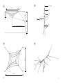
Wichtige Informationen: (siehe Grundriss-Zeichnungen Seite 9/10)
• Die Aufhängepunkte im Raum sind frei wählbar und müssen nicht zwingend auf einem Rechteck
und/oder der selben Höhe liegen. Je nach Richtung und Entfernung ändert sich das Erscheinungs-
bild des Lüsters. 1,2
• Die Position im Raum und die Form des Lüsters hängen vor allem vom Zug der Abspannseile ab.
Je stärker diese gespannt sind, desto straffer und folglich auch höher hängen die Netze (Prinzip
“Hängematte”).
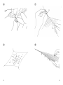
• Die einzelnen Netze können versetzt untereinander abgehängt werden. 1–3
• Auch Installationen mit mehreren Lüstern sind möglich (siehe Titelbild sowie Zeichnung 4).
• Die maximale Seillänge der Abspannungen beträgt 400 cm.
• Der mitgelieferte Wandspot Osram Halospot 111 mit 8° Ausstrahlungswinkel ist für Abstände von
150 cm bis 400 cm (gemessen von der Netzmitte) geeignet. Bei abweichenden Abständen ist das
Leuchtmittel auch mit Ausstrahlungswinkeln von 24° (für geringe Entfernungen) und 4° (für größere
Entfernungen) im Handel erhältlich.
Achtung: Detaillierte Informationen zur Montage der Leuchte entnehmen Sie bitte den beiliegenden
Lacrime del Pescatore Instructions.
Deutsch
English
1
Installation variants
Lacrime del Pescatore can be installed in any number of ways on ceilings or walls. The following in-
stallation variants are shown in this leaflet:
A) Ceiling version for high ceilings (pages 3/4)
B) Wall version (pages 5/6)
C) Ceiling-wall version (pages 7/8)
Important information: (see diagrams on pages 9/10)
• The suspension points in the room can be chosen freely and do not have to be at right-angles or
at the same height.The appearance of the chandelier varies according to the distance between the
suspension points and how they are aligned. 1,2
• The position and appearance of the chandelier depend above all on the tension of the suspension
cables.Tautening the cables will straighten and raise the nets (as with a hammock).
• The nets can be hung in an asymmetrical layered pattern. 1–3
• Installations with several chandeliers are also possible (see cover page and fig. 4on p. 10).
• The maximum length of the suspension cables is 400 cm.
• The light bulb supplied - Osram Halospot 111 with 8° beam angle - is suitable for distances of 150
cm to 400 cm (from the centre of the net). Bulbs with a beam angle of 24° (for shorter distances)
and 4° (for greater distances) are available from electrical retailers.
N.B.: For more detailed information on installing Lacrime del Pescatore, please see the enclosed
instructions for assembly.

Français
IItaliano
2
Installations spéciales
Lacrime del Pescatore peut être suspendu de toute façon imaginable au plafond ou au mur. Dans
cette fiche, les différents types d’installations spéciales sont présentés schématiquement:
A) Installation au plafond pour pièces à haut plafond (page 3/4)
B ) Installation murale (page 5/6)
C) Installation mur-plafond (page 7/8)
Informations importantes: (cf plans et dessins page 9/10)
• Les points de suspension sont à choisir librement dans la pièce et ne doivent pas forcément être
positionnés dans un coin rectangulaire et/ou à même hauteur. L’image du lustre change en fonction
de l’orientation et de la distance. 1 , 2
• La Position dans la pièce et la forme du lustre dépendent avant tout de la tension du hauban.
Plus celui-ci sera tendu, et serré par conséquent plus haut sera suspendu le filet (principe du
“hamac”).
• Les différents filets peuvent être suspendus les uns en dessous des autres de façon décalée. 1 –3
• Des installations avec plusieurs lustres sont aussi possibles (cf photo de couverture et dessin 4 ).
• La longueur maximale de câble de tension est de 400 cm.
• Le spot mural fourni Osram Halospot 111 avec 8° d’angle de diffusion est prévu pour un espace-
ment de 150 cm à 400 cm (mesuré du centre du filet). Pour des distances divergentes, l’halogène
Halospot est disponible dans le commerce avec des angles de diffusion de 24° (pour de plus faibles
distances) et 4° (pour de plus grosses distances).
Attention: veuillez consulter les informations détaillées de montage du luminaire dans notre fiche
d’instruction de ‘Lacrime del Pescatore’.
Installazioni speciali
Lacrime del Pescatore può essere montata a piacere al soffitto e/o alla parete. Questa aggiunta di
aggiunta contiene gli schemi relativi alle seguenti installazioni:
A) Installazione al soffitto per soffitti alti (pagg. 3/ 4)
B) Installazione alla parete (pagg. 5/6)
C) Installazione soffitto-parete (pagg. 7/8)
Informazioni importanti: (vedi gli schemi a pagg. 9/10)
• I punti di sospensione possono essere determinati liberamente e non devono necessariamente
formare un rettangolo e/o essere alla stessa altezza. A secondo della loro direzione e distanza varia
l’aspetto del lampadario. 1 , 2
• La posizione e la forma del lampadario dipendono soprattutto dal grado di tensione dei fili di
sospensione. Più sono tirati, più sono tesi e quindi anche più vicini al soffitto/parete (principio
dell’amaca’).
• Le singole reti possono essere sospese sfalsate. 1 –3
• E’ possibile anche l’installazione con più lampadari (vedi copertina e figura 4 ).
• La lunghezza massima dei fili di sospensione è di 400 cm.
• L’incluso faretto a parete Osram Holospot 111 con angolo d’irradiazione 8° è adatto per distanze
da 150 a 400 cm (misurata dal punto centrale della rete). In caso di distanze diverse sono disponi-
bili in commercio lampadine con angoli d’irradiazione di 24° (per distanze minori) e 4° (per dis-
tanze superiori).
Attenzione: Per informazioni dettagliate relative al montaggio della lampada consultare le incluse
istruzioni di ‘Lacrime del Pescatore’.
1
2
4-Punkt-Wandinstallation (Draufsicht) / 4-point wall installation (plan view)
Installation murale en 4 points (vue de dessus) / Installazione a parete 4 punti (vista dall’alto)
Decken-Wand-Installation (Draufsicht) / Ceiling-wall installation (plan view)
Installation murale-plafond (vue de dessus) / Installazioe parete – soffitto (vista dall’alto)
9

=
'
[=
;
<
'
' '
$
$
%
''
$EVWDQG0LWWH/VWHU:DQG'HFNH
<
$EVWDQG2EHUNDQWH/VWHU:DQGEHIHVWLJXQJ
;
$EVWDQG8QWHUNDQWH/VWHU:DQGEHIHVWLJXQJ
=
+|KHQXQWHUVFKLHGSUR0HWHU(QWIHUQXQJ
EK
$$
%
6HLWHQDQVLFKW
*UXQGULVV
:DQG'HFNHQLQVWDOODWLRQ
Grundriss schematisch / Plan: schematic / Plan schématique / Vista in pianta schematica
=
'
[=
;
<
'
' '
$
$
%
''
$EVWDQG0LWWH/VWHU:DQG'HFNH
<
$EVWDQG2EHUNDQWH/VWHU:DQGEHIHVWLJXQJ
;
$EVWDQG8QWHUNDQWH/VWHU:DQGEHIHVWLJXQJ
=
+|KHQXQWHUVFKLHGSUR0HWHU(QWIHUQXQJ
EK
$$
%
6HLWHQDQVLFKW
*UXQGULVV
:DQG'HFNHQLQVWDOODWLRQ
Schnitt schematisch / Section: schematic / Coupe schématique / Sezione schematica
D1Abstand Wand – Mitte Lüster / Distance wall - centre of chandelier / Distance mur – centre du lustre /
Distanza parete – punto centrale lampadario
XAbstand Unterkante Lüster – Wandbefestigung / Distance lower edge of chandelier – wall fixture /
Distance bord inférieur du lustre – fixation murale / Distanza estremità inferiore lampadario – punto di fissaggio alla parete
YAbstand Oberkante Lüster – Wandbefestigung / Distance top edge of chandelier – wall fixture /
Distance bord supérieur du lustre – fixation murale / Distanza estremità superiore lampadario – punto di fissaggio alla parete
ZHöhenunterschied pro Meter Entfernung / Height difference per metre of distance /
Différence de niveau par mètre de distance / Differenza d’altezza per ogni metro di distanza
8
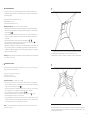
A) Deckeninstallation
Je größer das Deckenfeld ist, von dessen Eckpunkten A/B die Netze abgehängt werden, desto
tiefer hängt der Lüster und desto größer wird der Abstand der Netze zueinander. Der Decken-
abstand kann je nach Seilspannung leicht variiert werden. Bitte entnehmen Sie die Richtwerte
der untenstehenden Tabelle.
A) Ceiling installation
The larger the ceiling area from which the nets are suspended at points A and B, the lower
the chandelier will hang and the greater the distance between the nets will become. The dis-
tance from the ceiling can be varied to some extent by adjusting the cable tension. Reference
measurements are shown in the table below.
A) Installation plafond
Plus la superficie du plafond est large, auquel les filets seront suspendus par les points d’ancrage
A/B, plus le lustre sera suspendu bas et plus grande sera la distance entre les filets. L’espacement
du plafond peut varier légèrement selon la tension des câbles. Veuillez suivre les directives du
tableau ci-dessous.
A) Installazione al soffitto
Più è grande la superficie del soffitto, dove sono ancorati i punti A/B delle reti, più aumenta la
distanza del lampadario dal soffitto e maggiore sarà la distanza tra le singole reti. La distanza dal
soffitto può essere leggermente modificata agendo sulla tensione dei fili. I valori indicativi sono
riportanti nella tabella sottostante.
L
200 cm
300 cm
400 cm
500 cm
D
283 cm
424 cm
566 cm
707 cm
X
70–80 cm
75–90 cm
95–115 cm
100–130 cm
Y
15–20 cm
25–30 cm
40–50 cm
50–60 cm
Die Abstände X und Y variieren je nach Seilspannung. / Distances X and Y vary with the cable tension.
L’espacement entre X et Y varie selon la tension des câbles. / Le distanze X e Y variano secondo la tensione del filo.
*) Standardversion, vorinstalliert / Standard version, pre-installed / Version standard, pré-installée /
versione standard, premontata
*
3

<
;
'
$%
$ $
%
'
'LDJRQDOH'HFNHQIHOG
$%
6HLWHQOlQJH'HFNHQIHOG
< $EVWDQG2EHUNDQWH/VWHU'HFNH
;
$EVWDQG8QWHUNDQWH/VWHU'HFNH
$ $
%
%
*UXQGULVV
6HLWHQDQVLFKW
'HFNHQLQVWDOODWLRQ
Grundriss schematisch / Plan diagram / Plan schématique / Vista in pianta schematica
<
;
'
$%
$ $
%
'
'LDJRQDOH'HFNHQIHOG
$%
6HLWHQOlQJH'HFNHQIHOG
< $EVWDQG2EHUNDQWH/VWHU'HFNH
;
$EVWDQG8QWHUNDQWH/VWHU'HFNH
$ $
%
%
*UXQGULVV
6HLWHQDQVLFKW
'HFNHQLQVWDOODWLRQ
Schnitt schematisch / Section diagram / Coupe schématique / Sezione schematica
LSeitenlänge Deckenfeld / Lateral measurement ceiling area / Longueur du côté / Lunghezza lati
DDiagonale Deckenfeld / Diagonal measurement ceiling area / Diagonale / Diagonale
XAbstand Unterkante Lüster / Distance lower edge of chandelier / Distance bord inférieur / Distanza estremità inferiore
YAbstand Oberkante Lüster / Distance top edge of chandelier / Distance bord supérieur / Distanza estremità superiore
L
4
C) Decken-Wand-Installation
Auch eine kombinierte Abspannung von Decke und Wänden ist möglich.
Je tiefer der Abspannpunkt an der Wand gewählt wird, desto weiter entfernt vom Lüster muss der
Abhängepunkt an der Decke liegen (ca. 1 Meter Entfernung pro 20 cm Deckenabstand an der
Wand). Bitte entnehmen Sie die Richtwerte der untenstehenden Tabelle.
C) Ceiling-wall installation
A combined ceiling-wall attachment is also possible.
The lower the suspension point on the wall, the greater the required distance between the chande-
lier and the suspension point on the ceiling (approx 1 metre per 20 cm ceiling clearance at the wall).
Reference measurements are shown in the table below.
C) Installation mur-plafond
Un haubanage combiné du plafond au mur est possible.
Plus le point d’ haubanage au mur sera choisi bas, plus le point d’inclinaison devra être éloigné du
plafond (env. 1 mètre de distance par 20 cm de distance entre plafond et mur). Veuillez suivre les
directives du tableau ci-dessous.
C) Installazione soffitto-parete
E’ possibile anche un montaggio composto soffitto e pareti.
Più è basso il punto di fissaggio alla parete, più deve distare il punto di fissaggio al soffitto (ca. 1 metro
di distanza in più in orizzontale per ogni 20 cm di distanza in più dal soffitto del punto a parete) I va-
lori indicativi sono riportanti nella tabella sottostante.
D1
150 cm
200 cm
300 cm
400 cm
X
70–80 cm
75–90 cm
95–115 cm
115–135 cm
Y
15–20 cm
25–30 cm
40–55 cm
65–75 cm
7
Die Abstände X und Y variieren je nach Seilspannung. / Distances X and Y vary with the cable tension.
L’espacement entre X et Y varie selon la tension des câbles. / Le distanze X e Y variano secondo la tensione del filo.
Z =ca. 20 cm / Z = approx. 20 cm / Z = env. 20 cm / Z = ca. 20 cm

<
=
'
[=
;
'
$
$
%
'
$EVWDQG0LWWH/VWHU:DQG
<
$EVWDQG2EHUNDQWH/VWHU:DQGEHIHVWLJXQJ
;
$EVWDQG8QWHUNDQWH/VWHU:DQGEHIHVWLJXQJ
=
+|KHQXQWHUVFKLHGSUR0HWHU(QWIHUQXQJ
EK
$
%
*UXQGULVV
6HLWHQDQVLFKW
$
:DQGLQVWDOODWLRQ
Grundriss schematisch / Plan diagram / Plan schématique / Vista in pianta schematica
<
=
'
[=
;
'
$
$
%
'
$EVWDQG0LWWH/VWHU:DQG
<
$EVWDQG2EHUNDQWH/VWHU:DQGEHIHVWLJXQJ
;
$EVWDQG8QWHUNDQWH/VWHU:DQGEHIHVWLJXQJ
=
+|KHQXQWHUVFKLHGSUR0HWHU(QWIHUQXQJ
EK
$
%
*UXQGULVV
6HLWHQDQVLFKW
$
:DQGLQVWDOODWLRQ
Schnitt schematisch / Section diagram / Coupe schématique / Sezione schematica
B) Wandinstallation
Bei Abspannung der Netze von den Wänden kann der Lüster in jeder beliebigen Höhe im
Raum platziert werden. Je weiter die Wand entfernt ist, desto höher muss der Abspannungs-
punkt liegen (ca. 20 cm pro Meter Entfernung).
Bitte entnehmen Sie die Richtwerte der untenstehenden Tabelle.
B) Wall installation
With the nets attached to the walls, the chandelier can be positioned at any height in the
room. The greater the distance from the wall, the higher the suspension point must be (approx.
20 cm per metre of distance).
Reference measurements are shown in the table below.
B) Installation murale
Lors de l’haubanage aux murs des filets, le lustre peut être placé dans la pièce à n’importe
quelle hauteur. Plus le mur sera éloigné et plus haut doit se trouver le point d’haubanage
(env. 20 cm par mètre de distance).
Veuillez suivre les directives du tableau ci-dessous.
B) Installazione alla parete
Nel caso di fissaggio delle reti alle pareti, il lampadario può essere montato ad un’altezza qual-
siasi. Più la parete è distante, più alto deve essere il punto di fissaggio (ca. 20 cm in verticale
per ogni metro di distanza orizzontale).
I valori indicativi sono riportanti nella tabella sottostante.
D1
150 cm
200 cm
300 cm
400 cm
X
70–80 cm
75–90 cm
95–115 cm
115–135 cm
Y
15–20 cm
25–30 cm
45–55 cm
65–75 cm
Die Abstände X und Y variieren je nach Seilspannung. / Distances X and Y vary with the cable tension.
L’espacement entre X et Y varie selon la tension des câbles. / Le distanze X e Y variano secondo la tensione del filo.
Z =ca. 20 cm / Z = approx. 20 cm / Z = env. 20 cm / Z = ca. 20 cm
D1Abstand Wand – Mitte Lüster / Distance wall – centre of chandelier / Distance mur – centre du lustre /
Distanza parete – punto centrale del lampadario
XAbstand Unterkante Lüster – Wandbefestigung / Distance lower edge of chandelier – wall fixture /
Distance bord inférieur du lustre – fixation murale / Distanza estremità inferiore lampadario – punto di fissaggio alla parete
YAbstand Oberkante Lüster – Wandbefestigung / Distance top edge of chandelier – wall fixture /
Distance bord supérieur du lustre – fixation murale / Distanza estremità superiore lampadario – punto di fissaggio alla parete
ZHöhenunterschied pro Meter Entfernung / Height difference per metre of distance /
Différence de niveau par mètre de distance / Differenza d’altezza per ogni metro di distanza
56
-
 1
1
-
 2
2
-
 3
3
-
 4
4
-
 5
5
-
 6
6
-
 7
7
-
 8
8
-
 9
9
-
 10
10
-
 11
11
-
 12
12
-
 13
13
-
 14
14
-
 15
15
-
 16
16
-
 17
17
-
 18
18
-
 19
19
-
 20
20


Ingo Maurer Lacrime del Pescatore Bedienungsanleitung
- Typ
- Bedienungsanleitung
in anderen Sprachen
Verwandte Papiere
-
Ingo Maurer Use Me W. Bedienungsanleitung
-
-
-
-
-
-
-
-
-