Powerware 5125 P33 Installationsanleitung
- Typ
- Installationsanleitung

Powerware
®
5125
Installation Guide for IBM Applications
Guide d’installation pour applications IBM
Installationsanleitung für IBM-Anwendungen
Guida all’installazione per le Applicazioni IBM
Guía de instalación para aplicaciones de IBM
www.powerware.com

Powerware is a registered trademark and X-Slot and ConnectUPS are trademarks of Powerware Corporation.
Powerware est une marque déposée et X-Slot et ConnectUPS sont des marques commerciale de Powerware Corporation.
Powerware ist ein eingetragenes Warenzeichen und X-Slot und ConnectUPS sind ein Warenzeichen der Powerware
Corporation.
Powerware è un marchio di fabbrica depositato e X-Slot e ConnectUPS sono marchi di fabbrica della Powerware
Corporation.
Powerware es una marca comercial registrada y X-Slot y ConnectUPS son marcas comerical de Powerware Corporation.
Copyright 2001 Powerware Corporation, Raleigh, NC, USA. All rights reserved. No part of this document may be
reproduced in any way without the express written approval of Powerware Corporation.
Copyright 2001 Powerware Corporation, Raleigh, NC, Etats-Unis. Tous droits réservés. Aucune partie de ce document
ne peut être reproduite d’une quelconque manière sans l’accord écrit explicite de Powerware Corporation.
Copyright 2001 Powerware Corporation, Raleigh, NC, USA. Alle Rechte vorbehalten. Kein Teil dieser Druckschrift darf
ohne ausdrückliche schriftliche Genehmigung von Powerware Corporation auf irgendeine Weise vervielfältigt werden.
Copyright 2001 Powerware Corporation, Raleigh, NC, USA. Tutti i diritti riservati. Nessuna parte del presente
documento può essere riprodotta in alcun modo senza l’esplicita autorizzazione scritta di Powerware Corporation.
Copyright 2001 Powerware Corporation, Raleigh, NC, EE.UU. Todos los derechos reservados. Ninguna parte de este
documento se puede reproducir sin la autorización expresa por escrito de Powerware Corporation.

i
Powerware
®
5125 Installation Guide for IBM Applications : 164201356 B Uncontrolled Copy
TABLE OF CONTENTS
Installation 3.......................................................
Electrical Requirements 4.........................................................
UPS Setup 5..................................................................
Tools Required 5.............................................................
Checking the Battery Recharge Date 5.............................................
Rack-Mount Setup 6..........................................................
Installing Optional Equipment 7.....................................................
Power Management Software 7..................................................
Ground Bonding Screw 7.......................................................
Remote Emergency Power-Off 8..................................................
Cord Connections 9.............................................................
UPS Startup 15.................................................................
Service and Support 15...........................................................
TABLE DES MATIÈRES
Installation 17.......................................................
Spécifications électriques 18.......................................................
Installation de l’onduleur 19........................................................
Outils nécessaires 19..........................................................
Vérification de la date de charge de la batterie 19......................................
Configuration en baie 20........................................................
Installation des dispositifs optionnels 21...............................................
Logiciel Power Management 21...................................................
Visdemiseàlaterre 21........................................................
Téléalimentation d’urgence (REPO) 22...............................................
Connexion des cordons 24.........................................................
Mise en marche de l’onduleur 28....................................................
Service après-vente et assistance technique 29..........................................

Table of Contents
ii
Powerware
®
5125 Installation Guide for IBM Applications : 164201356 B Uncontrolled Copy
INHALTSVERZEICHNIS
Installation 31.......................................................
Elektrische Anforderungen 32.......................................................
Aufstellen der USV 33............................................................
Erforderliches Werkzeug 33......................................................
Überprüfen des Batterieladedatums 33..............................................
Aufstellung im Gestell 34.......................................................
Einbau von optionaler Ausrüstung 35..................................................
Power Management Software 35..................................................
Erdungsschraube 35...........................................................
Notausschaltung 36...........................................................
Kabelanschlüsse 38..............................................................
Inbetriebnahme der USV 43........................................................
Kundendienst und Unterstützung 43..................................................
SOMMARIO
Installazione 45......................................................
Requisiti elettrici 46..............................................................
Installazione dell’UPS 47..........................................................
Utensili richiesti 47............................................................
Verifica della data di ricarica della batteria 47.........................................
Installazione per il montaggio a rack 48..............................................
Installazione delle apparecchiature opzionali 49..........................................
Software per la gestione del risparmio energetico 49....................................
Vite di collegamento a massa 49..................................................
Spegnimento d’emergenza remoto 50...............................................
Connessione dei cavi 51...........................................................
Avvio dell’UPS 56...............................................................
Assistenza e supporto 57..........................................................

Table of Contents
iii
Powerware
®
5125 Installation Guide for IBM Applications : 164201356 B Uncontrolled Copy
CONTENIDO
Instalación 59.......................................................
Requisitos eléctricos 60...........................................................
Configuración del SIE 61..........................................................
Herramientas necesarias 61......................................................
Verificación de la fecha de recarga de las baterías 61....................................
Configuración de montaje en estante 62.............................................
Instalación de equipo opcional 63....................................................
Software de administración de energía 63............................................
Tornillo de unión a tierra 63......................................................
Parada de emergencia remota 64..................................................
Conexiones de cables 66..........................................................
Puesta en marcha del SIE 71........................................................
Servicio y soporte 71.............................................................

Table of Contents
iv
Powerware
®
5125 Installation Guide for IBM Applications : 164201356 B Uncontrolled Copy
This page intentionally left blank.
Page intercalaire.
Diese Seite wurde absichtlich nicht bedruckt.
Questa pagina è stata intenzionalmente lasciata bianca.
Esta página se dejo en blanco intencionalmente.

1
Powerware
®
5125 Installation Guide for IBM Applications : 164201356 B Uncontrolled Copy
INSTALLATION
The Powerware 5125 P33 UPS can be purchased separately or
factory-installed in an IBM pSeries rack.
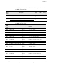
Table 1. Standard UPS Components
IBM
Model Number
IBM Part
Number
Powerware
Part Number
Description
P33 21P7219 05147155-3901 P33 UPS 2U high (in shipping carton or factory-installed in rack)
— 21P7229 05147532-3901 P33 Accessory Kit
6630 21P7220 103002291-002 4-Post Rail Kit (in shipping carton or factory-installed in rack)
9
8
5
1
4
0
H
3
0
1
8
(1) NEMA L6-30R to IEC 320-C20P, 6 ft
9851 40H3018 —
(1) IEC 320-C19 to NEMA L6-30P, 1.5 ft
9
8
5
5
1
7
G
1
8
6
5
(1) IEC 309-CEE17R, 2-pole, 3-wire, 32A to IEC 320-C20P, 2.5m
9855 17G1865 —
(1) IEC 320-C19R to IEC 309-CEE17P, 2-pole, 3-wire, 32A, 0.6m
Table 2. P33 UPS Components
Quantity
IBM Part
Number
Powerware
Part Number
Description
1 21P7219 05147155-3901 P33 UPS with Internal Battery Pack*
1 — — Front Bezel*
1Set — — Mounting Handles and Hardware*
*NOTE If the UPS is factory-installed in an IBM rack, these items are pre-assembled.

Installation
2
Powerware
®
5125 Installation Guide for IBM Applications : 164201356 B Uncontrolled Copy
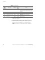
Table 3. P33 Accessory Kit Components
Quantity
IBM Part
Number
Powerware
Part Number
Description
1 — 164201355
Powerware 5125 User’s Guide
1 — 164201356
Powerware 5125 Installation Guide for IBM Applications
3 — 60420055 IEC 320-C13 to C14, 10A Equipment Power Cords (6 ft/1.8m)
1 — 05146745-31 Powerware Software Suite CD-ROM
1Bag — — Cord Rention Clips
1 — — REPO Connector
1 — 164201359
Multi-Server Module User’s Guide
3 — 124102022-002 UPS to Server Communication Cables (DB-9 to DB-9, 6 ft/1.8m)
NOTE For those items without an IBM Part Number, contact Powerware for additional parts.
Table 4. UPS Options
IBM
Model Number
IBM Part
Number
Powerware
Part Number
Description
6607 21P7221 05147156-3901 Optional Extended Battery Module (EBM) 2U*
2932 — 05146288-3901 ConnectUPS-MX SNMP Module
*NOTE Up to four EBMs may be connected to the UPS. If there are two UPSs in a rack, up to two EBMs may be connected
to each UPS.
Electrical Requirements
The UPS requires a dedicated branch circuit that meets the following
requirements:
:
16–32A, 200–240 Vac receptacle (type varies by country)
:
Single-phase
:
50–60 Hz
Refer to the pSeries Site and Hardware Planning Information Guide
(SA38-0508) for more information:
http://www-1.ibm.com/servers/eserver/pseries/library/hardware_docs

Installation
3
Powerware
®
5125 Installation Guide for IBM Applications : 164201356 B Uncontrolled Copy
Table 5. UPS Model Specifications
IBM Model Number P33
Output Receptacles (9) IEC 320-C13, (1) IEC 320-C19
Input Connection 16A, IEC 320-C20 input connector
Power Rating 3.0 kVA/2.7kW
Voltage 200–240V single-phase
Frequency 50/60 Hz, auto-sensing
NOTE For more information refer to “Specifications” in the
Powerware 5125 User’s Guide
.
UPS Setup
NOTE If your UPS is already installed in an IBM pSeries (RS/6000) system, then skip
to “Installing Optional Equipment” on page 5.
Tools Required
To assemble the components, the following tools may be needed:
:
Medium flat-bladed screwdriver
:
#2 Phillips screwdriver
Checking the Battery Recharge Date
Check the battery recharge date label located on the UPS carton.
NOTE If the battery recharge date has expired and the batteries have never been
recharged, contact your service representative (see “Service and Support” on page 13).

Installation
4
Powerware
®
5125 Installation Guide for IBM Applications : 164201356 B Uncontrolled Copy
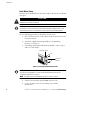
Rack-Mount Setup
The UPS can be installed in 19-inch racks and needs only 2U of valuable
rack space.
CAUTION
The UPS and Extended Battery Module are heavy. A minimum of two people are
required to lift the UPS into the rack.
NOTE Fixed mounting rails are required for each cabinet. If fixed rails are not already
installed in your rack, contact your local IBM representative to order a rail kit. If you
are installing the UPS in a non-IBM rack, contact your Powerware representative.
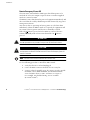
Use the following procedure to install the UPS in a rack:
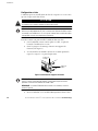
1. Place the UPS on a flat, stable surface with the front of the UPS
facing toward you.
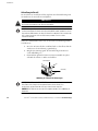
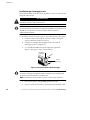
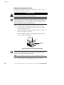
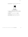
2. Attach the supplied mounting handles to the mounting
brackets (see Figure 1).
3. If installing optional Extended Battery Modules, repeat Steps 1
and 2 for each cabinet.
Mounting Handle
Mounting
Bracket
Figure 1. Installing the Mounting Brackets
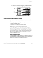
NOTE The UPS and EBMs MUST be installed at the bottom of the rack. If placed in a
rack with existing equipment, the rack must be reconfigured to allow the UPS
installation at the bottom of the rack.
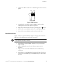
NOTE The EBMs must be installed below the UPS as shown in Figure 2.
4. Slide the UPS and any optional EBMs into the rack.
5. Secure the units to the rack according to the rail kit
instructions.

Installation
5
Powerware
®
5125 Installation Guide for IBM Applications : 164201356 B Uncontrolled Copy
6. Attach the front bezel to each unit (supplied in the UPS and
EBM shipping cartons).
UPS
Optional
EBMs
Figure 2. Rack-Mount UPS with EBMs
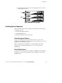
Installing Optional Equipment
This section describes the UPS options that should be installed before
starting up the UPS:
:
Power Management Software
:
Ground Bonding Screw
:
Remote Emergency Power-Off switch
Power Management Software
If you are installing power management software, use one of the
supplied communication cables to connect your computer to Port 1 on
the Multi-Server Module of the UPS.
Refer to the Multi-Server Module User’s Guide and the Powerware
Software Suite CD-ROM provided in the accessory kit for more
information.
Ground Bonding Screw
If your rack has conductors for grounding or bonding of ungrounded
metal parts, connect the ground cable (not included) to the ground
bonding screw.

Installation
6
Powerware
®
5125 Installation Guide for IBM Applications : 164201356 B Uncontrolled Copy
Remote Emergency Power-Off
The Powerware 5125 includes a REPO port that allows power to be
switched off at the UPS output receptacles from a customer-supplied
switch in a remote location.
The REPO feature shuts down the protected equipment immediately and
does not follow the orderly shutdown procedure initiated by any power
management software.
Any devices that are operating on battery power are also shut down
immediately. When the REPO switch is re-opened, the equipment will
not return to battery power until the UPS is manually restarted.
If the Off
button is pressed after the REPO is activated, the UPS
remains in Standby mode when restarted until the On
button is
pressed.
WARNING
The REPO circuit is an IEC 60950 safety extra low voltage (SELV) circuit. This circuit
must be separated from any hazardous voltage circuits by reinforced insulation.
CAUTION
To ensure the UPS stops supplying power to the load during any mode of operation,
the input power must be disconnected from the UPS when the emergency power-off
function is activated.
NOTE The REPO function activates when the REPO contacts close.
Use the following procedure to install the REPO switch:
1. Verify that the UPS is off and unplugged.
2. Locate the REPO connector from the P33 accessory kit.
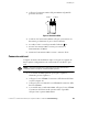
3. Connect isolated, normally-open, dry contacts (rated at 60 Vdc
maximum, 30 Vac RMS maximum, and 20 mA maximum)
across the REPO device to Pin 1 and Pin 2 (see Figure 3).
Use stranded, non-shielded wiring, size 18–22 AWG
(0.75 mm
2
–0 mm
2
).

Installation
7
Powerware
®
5125 Installation Guide for IBM Applications : 164201356 B Uncontrolled Copy
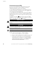
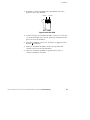
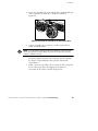
4. Connect the REPO connector to the REPO port on the UPS rear
panel.
Pin 1 Pin 2
Figure 3. REPO Connector
5. Verify that the externally-connected REPO switch is off to
enable power to the UPS output receptacles.
6. Plug in the UPS and start the UPS by pressing the On
button.
7. Turn on the external REPO switch to test the REPO function.
8. Turn off the external REPO switch and restart the UPS.
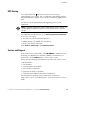
Cord Connections
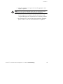
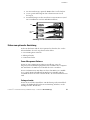
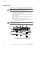
Figure 4 shows a typical installation. Figure 6 on page 10 shows four
different rack configurations with cord connections.
NOTE Do not make unauthorized changes to the UPS; otherwise, damage may occur
to your equipment and void your warranty.
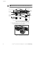
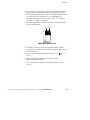
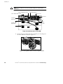
1. If installing an optional EBM, continue to Step 2; otherwise,
skiptoStep5.
2. Plug the EBM cable into the UPS battery connector (see
Figure 4).
3. Plug the other end of the EBM cable into the EBM battery
connector.
4. If installing a second EBM, plug the EBM cable into the battery
connector of each EBM. Up to four EBMs may be connected to
the UPS.

Installation
8
Powerware
®
5125 Installation Guide for IBM Applications : 164201356 B Uncontrolled Copy
NOTE If there are two UPSs in a rack, up to two EBMs may be connected to each
UPS.
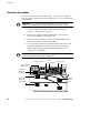
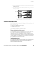
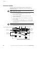
Ground Bonding
Screw
UPS Battery
Connector
EBM
Cable
Output Receptacles
Multi-Server Module Port 1
EBM Battery
Connectors
Power Cord
Circuit
Breakers
Figure 4. Typical Installation with Two EBMs
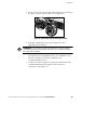
5. Insert the supplied cord retention clips by each output
receptacle that will be used (see Figure 5).
Figure 5. Attaching the Cord Retention Clips

Installation
9
Powerware
®
5125 Installation Guide for IBM Applications : 164201356 B Uncontrolled Copy
6. Plug the equipment to be protected into the appropriate UPS
output receptacles.
NOTE If you are using the Load Segment feature, see the
Powerware 5125 User’s
Guide
for more information on controlling and assigning the load segments.
DO NOT protect laser printers with the UPS because of the
exceptionally high power requirements of the heating elements.
7. Bend and twist the cord retention clips around the equipment
power cords to secure the cord connections (see Figure 5).

Installation
10
Powerware
®
5125 Installation Guide for IBM Applications : 164201356 B Uncontrolled Copy
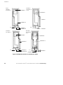
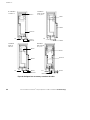
NOTE 1
NOTE 2A
NOTE 2B
NOTE 3
NOTE 4
NOTE 1
NOTE 1
NOTE 1
NOTE 2A
NOTE 2B
NOTE 2B
NOTE 3
NOTE 3
NOTE 3
NOTE 3
P33
P33
P33
P33s
Dual-Redundant
with PDB 9171
Dual-Redundant
with PDB 9174
and 9173
Dual-Redundant
with PDB 9171
and 6171
Non-Redundant
with PDB 9171
Figure 6. Rack Configurations and Cord Connections

Installation
11
Powerware
®
5125 Installation Guide for IBM Applications : 164201356 B Uncontrolled Copy
: NOTE 1 Rack Interconnect Cords: IEC 320-C13 to C14 supplied with rack devices.
: NOTE 2 UPS Jumper Cords:
IBM
Model
Number
Description
IBM
Type
IBM Part
Number
Country
9851
Note 2A: (1) NEMA L6-30R to IEC 320-C20P, 6 ft
Type 12 40H3018 Various
Note 2B: (1) IEC 320-C19 to NEMA L6-30P, 1.5 ft
y
p
9855
Note 2A: (1) IEC 309-CEE17R, 2-pole, 3-wire, 32A to IEC 320-C20P, 2.5m
Type 46 17G1865 Various
Note 2B: (1) IEC 320-C19R to IEC 309-CEE17P, 2-pole, 3-wire, 32A, 0.6m
y
p
: NOTE 3 Rack Power Cords:
IBM
Model
Number
Description IBM Type
IBM Part
Number
Country
9800 NEMA L6-30P Type 12 11F0113 Various
9801 R&S 3750 Type 40 46F4594 Various
9822 PDL 250V, 30A Type PDL (Wilco) 11F0106 Required for: Australia
9823 IEC 309-CEE17, 2-pole, 3-wire, 32A Type 46 21H7693 Various
9824 NEMA L6-30P Type 12 11F0113 Many AFE countries
9826 PDL 250V, 30A Type PDL 11F0107 Required for: New Zealand
9835 KP 250V, 30A Type KP 87G6067 Required for: Korea, China
9852 NEMA L6-30P Type 12 11F0113 Various
9856 IEC 309-CEE17, 2-pole, 3-wire, 32A Type 46 21H7693 Various
9862 NEMA L6-30P Type 12 11F0114 Required for: Chicago – United States
9864 R&S 3750 Type 40 46F4594 Various
9865 R&S 3750 Type 40 46F4593 Required for: Chicago – United States
9869 PDL 250V, 30A Type PDL 11F0107 Required for: New Zealand
9870 PDL 250V, 30A Type PDL (Wilco) 11F0106 Required for: Australia
9873 KP 250V, 30A Type KP 87G6067 Required for Korea, China
9986 NEMA L6-30P Type 12 11F0114 Required for: Chicago – United States
9987 R&S 3750 Type 40 46F4593 Required for: Chicago – United States

Installation
12
Powerware
®
5125 Installation Guide for IBM Applications : 164201356 B Uncontrolled Copy
: NOTE 4 Rack Power Cords:
IBM
Model
Number
Description IBM Type
IBM Part
Number
Country
9866 CEE7VII Type 18 14F1554 Required for: Austria, Czech Republic, Estonia,
Finland, Russia, Latvia, Lithuania, Portugal, Sweden
and Turkey
9867 SABS 164 BS 546 Type 22 14F1557 Required for: South Africa
9871 IEC-309 P+N+G, 3-pin, 16A Type 46 14F1555 Required for: Denmark, Switzerland and
Liechtenstein
9872 SII 32 – 1971 Type 32 14F1561 Required for: Israel
8. Plug the detachable UPS power cord into the input connector
on the UPS rear panel.
9. Plug the UPS power cord into a power outlet. All front panel
indicators flash briefly while the UPS conducts a self-test.
When the self-test is complete, the
indicator flashes,
indicating the UPS is in Standby mode with the equipment
offline.

Installation
13
Powerware
®
5125 Installation Guide for IBM Applications : 164201356 B Uncontrolled Copy
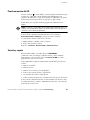
UPS Startup
Press and hold the On button until you hear the UPS beep
(approximately one second). The
indicator stops flashing and the
bar graph indicators display the percentage of load being applied to the
UPS.
The UPS is now in Normal mode and supplying power to your
equipment.
NOTE The batteries charge to 90% capacity in approximately 3 hours. However, it is
recommended that the batteries charge for 24 hours after installation or long-term
storage.
For additional P33 information, go to www.oem.powerware.com/ibm-ups
then select your region:
:
The Americas (North and South America)
:
EMEA (Europe, the Middle East and Africa)
:
APAC (Asia Pacific and China)
Click
Products, 9910 Solutions,andPowerware pSeries.
Service and Support
In the United States and Canada, call 1-800-IBMSERV (1-800-426-7378).
In Europe, the Middle East, and Africa (EMEA); Latin America; or
Asia-Pacific, call the
IBM office that services your account.
Please have the following information ready when you call for service:
:
Model number
:
Serial number
:
Version number (if available)
:
Date of failure or problem
:
Symptoms of failure or problem
:
Customer return address and contact information
For information regarding routine maintenance and battery
replacement, refer to “UPS Maintenance” in the Powerware 5125 User’s
Guide.

Installation
14
Powerware
®
5125 Installation Guide for IBM Applications : 164201356 B Uncontrolled Copy
This page intentionally left blank.
Seite wird geladen ...
Seite wird geladen ...
Seite wird geladen ...
Seite wird geladen ...
Seite wird geladen ...
Seite wird geladen ...
Seite wird geladen ...
Seite wird geladen ...
Seite wird geladen ...
Seite wird geladen ...
Seite wird geladen ...
Seite wird geladen ...
Seite wird geladen ...
Seite wird geladen ...
Seite wird geladen ...
Seite wird geladen ...
Seite wird geladen ...
Seite wird geladen ...
Seite wird geladen ...
Seite wird geladen ...
Seite wird geladen ...
Seite wird geladen ...
Seite wird geladen ...
Seite wird geladen ...
Seite wird geladen ...
Seite wird geladen ...
Seite wird geladen ...
Seite wird geladen ...
Seite wird geladen ...
Seite wird geladen ...
Seite wird geladen ...
Seite wird geladen ...
Seite wird geladen ...
Seite wird geladen ...
Seite wird geladen ...
Seite wird geladen ...
Seite wird geladen ...
Seite wird geladen ...
Seite wird geladen ...
Seite wird geladen ...
Seite wird geladen ...
Seite wird geladen ...
Seite wird geladen ...
Seite wird geladen ...
Seite wird geladen ...
Seite wird geladen ...
Seite wird geladen ...
Seite wird geladen ...
Seite wird geladen ...
Seite wird geladen ...
Seite wird geladen ...
Seite wird geladen ...
Seite wird geladen ...
Seite wird geladen ...
Seite wird geladen ...
Seite wird geladen ...
Seite wird geladen ...
Seite wird geladen ...
-
 1
1
-
 2
2
-
 3
3
-
 4
4
-
 5
5
-
 6
6
-
 7
7
-
 8
8
-
 9
9
-
 10
10
-
 11
11
-
 12
12
-
 13
13
-
 14
14
-
 15
15
-
 16
16
-
 17
17
-
 18
18
-
 19
19
-
 20
20
-
 21
21
-
 22
22
-
 23
23
-
 24
24
-
 25
25
-
 26
26
-
 27
27
-
 28
28
-
 29
29
-
 30
30
-
 31
31
-
 32
32
-
 33
33
-
 34
34
-
 35
35
-
 36
36
-
 37
37
-
 38
38
-
 39
39
-
 40
40
-
 41
41
-
 42
42
-
 43
43
-
 44
44
-
 45
45
-
 46
46
-
 47
47
-
 48
48
-
 49
49
-
 50
50
-
 51
51
-
 52
52
-
 53
53
-
 54
54
-
 55
55
-
 56
56
-
 57
57
-
 58
58
-
 59
59
-
 60
60
-
 61
61
-
 62
62
-
 63
63
-
 64
64
-
 65
65
-
 66
66
-
 67
67
-
 68
68
-
 69
69
-
 70
70
-
 71
71
-
 72
72
-
 73
73
-
 74
74
-
 75
75
-
 76
76
-
 77
77
-
 78
78


Powerware 5125 P33 Installationsanleitung
- Typ
- Installationsanleitung
in anderen Sprachen
- français: Powerware 5125 P33 Guide d'installation
- español: Powerware 5125 P33 Guía de instalación
- italiano: Powerware 5125 P33 Guida d'installazione
Verwandte Artikel
Andere Dokumente
-
Eaton Powerware 5125 Installationsanleitung
-
 BlueWalker PowerWalker VI 1500RT LCD/UK Benutzerhandbuch
-
-
Fortress Technologies AS/400 Installation and Service Manual
-
 PowerWalker VFI 10000 PRT HID Bedienungsanleitung
-
-
-
Eaton Powerware 9910-P30 Installationsanleitung
-
Schneider Electric Easy UPS On-Line Benutzerhandbuch
-

