SICK SLT Smart Light Tower Bedienungsanleitung
- Typ
- Bedienungsanleitung

O P E R A T I N G I N S T R U C T I O N S
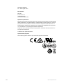
SLT
Smart Light Tower


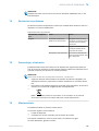
Described product
SLT - Smart Light Tower
Manufacturer
SICK AG
Erwin-Sick-Str. 1
79183 Waldkirch
Germany
Legal information
This work is protected by copyright. Any rights derived from the copyright shall be
reserved for SICK AG. Reproduction of this document or parts of this document is
only permissible within the limits of the legal determination of Copyright Law. Any modi‐
fication, abridgment or translation of this document is prohibited without the express
written permission of SICK AG.
The trademarks stated in this document are the property of their respective owner.
© SICK AG. All rights reserved.
Original document
This document is an original document of SICK AG.
2006/42/EC
NO
SAFETY
8026183 / 2021-04-29 | SICK
Subject to change without notice
3

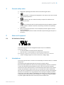
Contents
1 General safety notes......................................................................... 5
2 Notes on UL approval........................................................................ 5
2.1 UL Satisfaction Ratings............................................................................ 5
3 Intended use...................................................................................... 5
4 Product description........................................................................... 6
4.1 Product characteristics............................................................................ 6
5 Operating elements and status indicators.................................... 6
6 Mounting............................................................................................. 7
6.1 Scope of delivery....................................................................................... 7
6.2 Mounting requirements............................................................................ 7
6.3 Notes on mounting................................................................................... 7
6.4 Mounting on the machine housing.......................................................... 7
6.5 Mounting on a rod.................................................................................... 8
6.6 Mounting the Smart Light Buzzer SLB.................................................... 8
7 Electrical installation........................................................................ 9
7.1 Attaching connection cable...................................................................... 10
8 Operation............................................................................................ 11
8.1 Operating modes...................................................................................... 11
8.2 Configuration............................................................................................. 12
9 Troubleshooting................................................................................. 19
10 Disassembly and disposal............................................................... 19
11 Maintenance...................................................................................... 19
12 Technical data.................................................................................... 20
12.1 Technical specifications........................................................................... 20
12.2 Dimensional drawings.............................................................................. 20
13 Annex.................................................................................................. 21
CONTENTS
4
8026183 / 2021-04-29 | SICK
Subject to change without notice

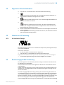
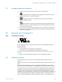
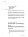
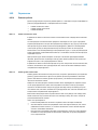
1 General safety notes
■
Read these operating instructions before commissioning the device.
■
Connection, mounting and configuration of the device must only be carried
out by qualified personnel.
■
2006/42/EC
NO
SAFETY
This device does not constitute a safety component as defined in the
Machinery Directive.
■
Do not install the device in places exposed to direct UV radiation (sunlight)
or other weather conditions unless this is expressly permitted in the operating
instructions.
■
When commissioning the device, ensure adequate protection against moisture
and contamination.
■
These operating instructions contain information required during the life cycle of
the device.
2 Notes on UL approval
2.1 UL Satisfaction Ratings
The Smart Light Tower is a UL Recognized Component (file no. E198242).
Standard for safety:
•
UL 508, Standard for Industrial Control Equipment
•
CSA C22.2 No. 14-18, Standard for Industrial Control Equipment
The following compliance requirements of UL certification must be considered:
•
A class 2 voltage supply unit must be used for the voltage supply
3 Intended use
The Smart Light Tower SLT is used for the visual display of machine states or to indicate
filling levels.
The optional Smart Light Buzzer SLB unit is used for acoustic alarms.
Both the 20 LED segments and the acoustic Smart Light Buzzer SLB can be switched
on and off individually. Parameterization for this is done via the IO-Link interface.
Intended use requires that the device is used industrially indoors without any specific
climatic and atmospheric requirements. Any use outside of the areas mentioned in
each case will be considered to be incorrect use and void any warranty claims against
SICK AG. The intended use is only guaranteed if the housing is completely mounted.
In the event of any other usage or modification to the device (e.g., due to opening the
housing during mounting and electrical installation) or changes to the SICK software,
any claims against SICK AG under the warranty will be rendered void.
GENERAL SAFETY NOTES 1
8026183 / 2021-04-29 | SICK
Subject to change without notice
5

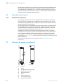
4 Product description
4.1 Product characteristics
The Smart Light Tower SLT is a signal lamp used for the visual display of, for example,
machine states or to indicate filling levels. With the Smart Light Buzzer SLB unit, the
device is also suitable for issuing acoustic alarms if needed.
The Smart Light Tower is an IO-Link device that communicates exclusively via the IO-
Link protocol with the higher-level IO-Link master assembly. The IO-Link communication
interface enables direct access to process data and parameter values. The required
IODD can be found at http://www.sick.com/slt.
The device has 20 LED segments. According to IO-Link standards, these LED segments
and the optional buzzer unit can be configured and operated individually. It is possible
to change device parameters during operation. Configuration is performed either via
the SICK SOPAS ET software (available free of charge at www.sick.com) or directly via
the PLC interface.
Further specifications can be found in the technical data (see "Technical data",
page 20).
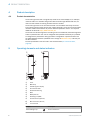
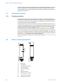
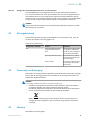
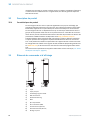
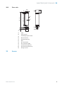
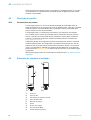
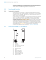
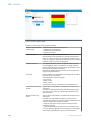
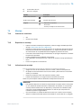
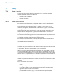
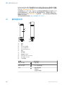
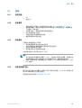
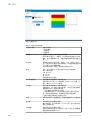
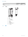
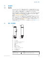
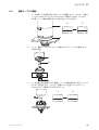
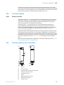
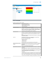
5 Operating elements and status indicators
1
4
5
5
6
7
2
3
8
9
ß
à
1
Cover
2
Main body
3
20 LED segment display
4
IO-Link status LED
5
Positionsmarkierung
6
Base
7
Waterproof foil
8
Fastening nut (M30)
9
Summereinheit (Optional)
ß
M12 connection (IO-Link)
à
½ inch thread
Display Description
Green LED lights up Device switched on
4 PRODUCT DESCRIPTION
6
8026183 / 2021-04-29 | SICK
Subject to change without notice

Display Description
Green LED flashes IO-Link connection active
off - Device not ready
- No voltage
- Voltage below the limit values
6 Mounting
6.1 Scope of delivery
•
SLT
•
Quickstart
6.2 Mounting requirements
•
For the typical space requirements for the device, see the type-specific dimen‐
sional drawing, see "Technical data", page 20.
•
Comply with technical data, such as the permitted ambient conditions for opera‐
tion of the device (e.g., temperature range, EMC interference emissions, ground
potential).
•
To prevent condensation, avoid exposing the device to rapid changes in tempera‐
ture.
•
Protect the device from direct sunlight.
•
Only mount the device using the threaded mounting holes provided.
•
Shock and vibration resistant mounting.
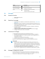
6.3 Notes on mounting
The following requirements are necessary for proper installation:
•
Switch off the voltage supply before you mount or replace the devices.
•
Do not apply excessive force when mounting/dismounting the signal lamp and
buzzer unit.
•
Perform installation on a rugged, level surface.
•
Install this device where there is no excessive vibration.
Note the maximum permissible tightening torque for the device of 4.5 Nm.
NOTE
•
This product comes with a waterproof foil on the bottom of the bracket (1 mm).
This must be used during installation. We recommend, however, applying sealant
between the device and the installation surface to guarantee the watertightness
of the device if there are any irregularities present in the installation surface.
•
If sealing from the nut side (interior of the machine) is required, apply a suitable
sealing compound for the M30 nut to the
1
/
2
-inch NPT thread.
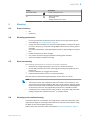
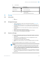
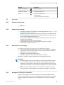
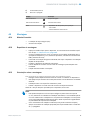
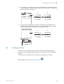
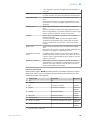
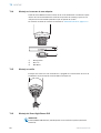
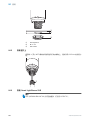
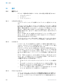
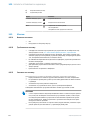
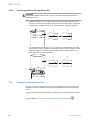
6.4
Mounting on the machine housing
Unscrew the M30 nut on the bottom of the signal lamp. Insert the bottom part of the
signal lamp through the mounting surface and secure the lamp to the machine using
the M30 nut and 4.5 Nm tightening torque.
Attachment of the connection cable is described in "Electrical installation", page 9.
MOUNTING 6
8026183 / 2021-04-29 | SICK
Subject to change without notice
7

1
2
3
1
Mounting surface
2
Ø 31 mm
3
M30 Nut
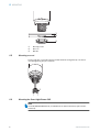
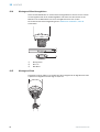
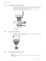
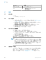
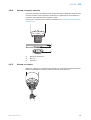
6.5 Mounting on a rod
Screw a rod with ½-inch NPT onto the female thread of the signal lamp. The recom‐
mended tightening torque is 2.25 Nm.
1
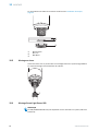
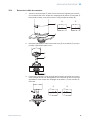
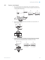
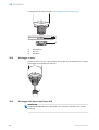
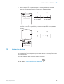
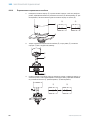
6.6 Mounting the Smart Light Buzzer SLB
NOTE
The SLB (SLB060-0B010K700) is available as an optional accessory (part number
6076072).
6 MOUNTING
8
8026183 / 2021-04-29 | SICK
Subject to change without notice

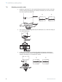
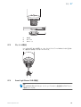
1.
To unlock it, rotate the cover (1) on the top of the signal lamp in the counterclock‐
wise direction. Lift up the released cover. Note the position markings (2 Locked;
3 Unlocked).
2 3
1
2.
Locate the Smart Light Buzzer (1) on the signal lamp with the position markers as
shown. To lock the buzzer unit and signal lamp together, turn the signal lamp in the
clockwise direction. (2 Unlocked; 3 Locked).
2 3
1
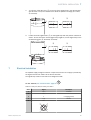
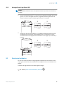
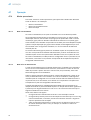
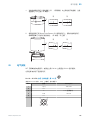
7 Electrical installation
No separate supply voltage connection is required for the SLT. The supply is provided by
the higher-level IO-Link master via the IO-Link interface.
The signal lamp must be connected in a voltage-free state.
U
B
: 18... 30 V DC, see "Technical data", page 20
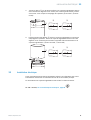
Table 1: IO-Link port, M12, A-coded, port class A
SLT Signal Description
1 + (L+) +24 V DC
2 n.c. -
3 L- 0 V (logic ground)
4 C/Q IO-Link
5 n.c. -
3
4
2
1
5
ELECTRICAL INSTALLATION 7
8026183 / 2021-04-29 | SICK
Subject to change without notice
9

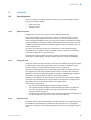
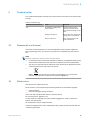
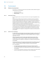
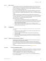
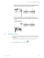
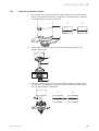
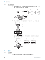
7.1 Attaching connection cable
1.
Rotate the main body (1) in the counterclockwise direction to unlock it. Note the
position markings while doing so (2 Locked; 3 Unlocked). You can now remove
the main body from the base (4).
2 3
1
4
2.
Now connect the connecting cable (2) to the M12 port (1) on the main body. (3
min. internal diameter)
1
2
3
Ø 17 (0.67)
3. Locate the main body in the base bracket again and rotate the main body in
the clockwise direction to secure the signal lamp. Pay attention to the position
markers while doing so. (1 Unlocked; 2 Locked)
1 2
7
ELECTRICAL INSTALLATION
10
8026183 / 2021-04-29 | SICK
Subject to change without notice

8 Operation
8.1 Operating modes
There are 3 different operating modes for the SLT, which are used to display various
warning and indicator signals:
•
Signal lamp mode
•
Filling level mode
•
Animation mode
8.1.1 Signal lamp mode
In Signal lamp mode, the SLT can be used as a standard signal lamp.
The 20 LED segments can be divided into a maximum of five groups. When evenly
distributed, four LEDs together always form a group. The number of LEDs per group
can be changed individually. Even if only one group is activated, all 20 LEDs are always
used for visualization. Exception: If the group separation function is activated, one row
of LEDs is switched off between the individual segments and the remaining number of
LEDs is reduced to 15.
The colors of the different groups can be selected from a color palette with eight
predefined colors. In addition, another individual color from a total of 21 predefined
colors can be added to the color palette here.
In Signal lamp mode, the LEDs can be set as either continuous light, flashing light,
strobe light, or pulsating light. The light animation frequency can be set individually.
8.1.2 Filling level mode
Filling level mode is used when the SLT is used as a level indicator or filling level display.
For this purpose, a level value is specified in the process data. The higher the level
value (in percent), the more LEDs are switched on at the signal lamp.
Each of the 20 LED segments can be individually colored from 21 predefined colors.
As in Signal lamp mode, each individual segment can be configured with a different
light pattern. Continuous light, flashing light, strobe light or pulsating light is available
for selection. The light animation frequency can be set individually.
Switching on the LEDs can be done either from the bottom end of the device upwards
or from the top end downwards. It is also possible for the segments to change color or
light pattern as soon as the segment above them begins to glow.
There are three options here:
•
The previously activated segments retain their light animation.
•
The segments that are already illuminated stop their light pattern animation as
soon as a new segment is added, but remain activated. Only the uppermost
segment shows an animation.
•
All segments show the light pattern of the uppermost segment to draw attention to
the current filling level, e.g. in the event of an overflow warning.
8.1.3 Animation mode
Animation mode is used to demonstrate the range of functions of the signal lamp. Here
the 20 different LED segments are switched on one after the other in a configured
sequence. In Animation mode, each LED segment of the SLT can be configured individ‐
ually.
OPERATION 8
8026183 / 2021-04-29 | SICK
Subject to change without notice
11

For coloring there are 21 predefined colors are available. In Animation mode, the LEDs
can be set as either continuous light, flashing light, strobe light, or pulsating light. The
light animation frequency can be set individually.
Switching on the LEDs can be done either from the bottom end of the device upwards
(bottom up) or from the top end downwards (top down). It is also possible for the
segments to change color or light pattern as soon as the segment above them begins to
glow.
There are three options here:
•
The previously activated segments retain their light animation.
•
The segments that are already illuminated stop their light pattern animation as
soon as a new segment is added, but remain activated. Only the uppermost
segment shows an animation.
•
All segments show the light pattern of the uppermost segment.
•
Other properties of the animation, e.g. loop/bounce effect, can also be set in this
mode.
8.2 Configuration
The SLT can be configured and controlled in three different ways:
1 Via SiLink2 IO-Link master and SOPAS ET with extensive graphical user interface
based on the SDD
2 Via IO-Link master (e.g. SIG200) and generic user interface based on the IODD
3 Via IO-Link master with direct access to the device parameters via IO-Link service
and process data (e.g. PLC with IO-Link master terminal)
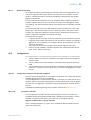
8.2.1.1 Configuration via SiLink2 master and SOPAS ET
The SLT can be configured on a PC (running Microsoft Windows) using the SOPAS
Engineering Tool (SOPAS Et for short) software.
An IO-Link master is required for configuration and operation of the SLT. When using the
SiLink2 IO-Link master, a comprehensive graphical user interface is available to assist
during configuration. The required SiLink2 IO-Link master can be ordered separately.
The SOPAS Engineering Tool application can be downloaded at www.sick.com.
8.2.1.1.1 SDD installation
A SOPAS Device Description (SDD) is required in order to configure the SLT via graphic
user interface. Start SOPAS ET and install the SDD of the SLT as described in the
following section.
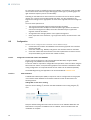
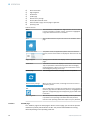
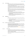
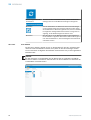
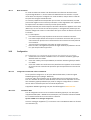
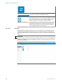
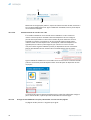
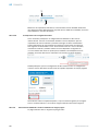
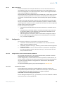
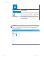
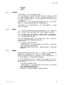
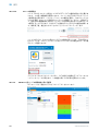
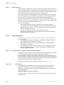
Adding SDD via the device catalog
Open the device catalog (1) and then the SDD installation menu using the gear (2)
icon:
1
2
Keep the default settings and select the SLT from the list of available SDDs after the
SDD search is complete. The SDD will now be installed, close the window when the
installation is complete.
8 OPERATION
12
8026183 / 2021-04-29 | SICK
Subject to change without notice

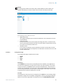
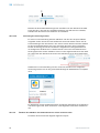
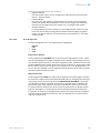
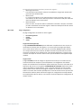
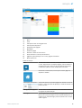
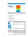
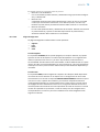
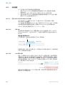
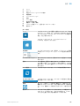
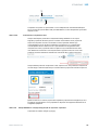
8.2.1.1.2 Establishing connection to the SLT
A connection between SOPAS ET and the SLT must now be established via SiLink2
master. The device search can be used for this purpose. Open the search settings
using the button in the lower right corner of the window. Select the interface-based
search and make sure that the “IO-Link communication” entry is selected in the
following window. If desired, the configured device search can be saved under
a user-defined name in the next step. SOPAS ET now searches for connected IO-
Link devices. After the search is finished, drag the found SLT to the project area:
SOPAS will now establish a connection to the SLT via IO-Link. You can identify a
successful connection by the green status display of the device tile in the project area:
Double-clicking on the device tile opens the graphical user interface for configuration
and control of the SLT, whose functions are explained in the following sections.
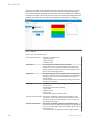
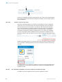
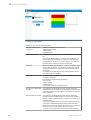
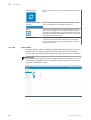
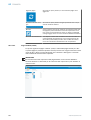
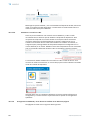
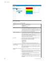
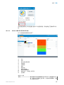
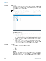
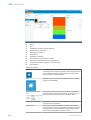
8.2.1.2 Overview of SOPAS ET and the standard functions on the individual pages
The pages for the SLT have the following general layout:
12 3 7 8 9
ß
à
4
5
6
1
Menu
2
Start
3
Display of the current navigation level
OPERATION 8
8026183 / 2021-04-29 | SICK
Subject to change without notice
13

4
Device information
5
Page navigation
6
Notifications
7
Update page
8
Restore factory settings
9
Activate/Deactivate Edit mode
ß
Parameterization page, with sub-pages if applicable
à
Operating mode
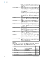
Table 2: Function
Menu Click this button to show/hide the “Page selection” menu to make
it easier to navigate on smaller screens. The button is highlighted
in light blue when the device tree is hidden.
Start Click the Start button at any time to return to the “STATUS” device
page.
Device information The product name, the application-specific name, the firmware
version, and the serial number are displayed in this area at the top
left.
Page navigation Clicking on the individual levels displays different parameterization
pages.
Notifications Notifications for the SLT are displayed at the bottom of the screen.
They are provided for informational purposes when exchanging
parameterizations or when errors occur. Each notification can be
acknowledged by clicking on the entry.
Update page After clicking on this button, the page contents are updated.
Restore factory settings When you click on this button, all settings of the SLT are reset to
their factory values.
Edit Click the Edit button to change the settings on the current parame‐
terization page. When the Edit button is pressed, it is highlighted in
light blue. Configurable pages are displayed in gray until Edit mode
is activated.
Operating mode With the SLT, there is only the RUN operating mode. No password
is provided for this operating mode. With other SICK products,
there are other operating modes that require entry of a password.
8.2.1.2.1 STATUS page
The “STATUS” page is the start page for the SLT. On this page, you can set the process
data that is cyclically transmitted to the SLT. The process data available for writing
differs depending on the operating mode set.
8 OPERATION
14
8026183 / 2021-04-29 | SICK
Subject to change without notice

NOTICE
For writing process data on the status side, at least SOPAS ET version V2021.2 is
required. Alternatively, an IO-Link master can be used to write the process data.
The following process data can be set:
•
Signal lamp mode
The configured LED groups as well as the SLB buzzer can be switched on and off
via the switches.
•
Filling level mode
Here the text field can be used to specify the filling level value in 0-100% format,
which is transmitted cyclically to the SLT as process data. The SLB buzzer can also
be turned on and off with a switch here.
•
Animation mode
In this mode, the animation can be switched on and off. The animation can also
be reset and its speed can be adjusted. The SLB buzzer can also be turned on and
off with a switch here.
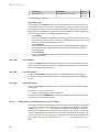
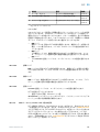
8.2.1.2.2 Configuration page
The Configuration page is divided into four tabs:
•
General
•
Color
•
Buzzer
•
Alarm
General tab
In the GENERAL tab, the SLT can be completely shut off. In addition, the brightness of
the lamp can be adjusted. The slider can be used to set values between 0 and 100%
in 10% increments. The Find me function can also be activated here. If this function is
activated, the IO-LINK LED in the lower part of the SLT starts flashing with a frequency
of 1 Hz (clock/pause 50%) until the button is clicked again. This function can be used
to identify devices that have already been mounted.
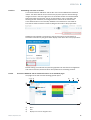
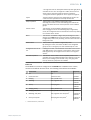
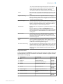
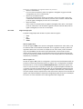
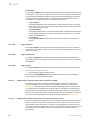
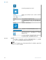
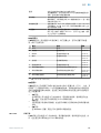
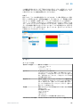
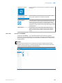
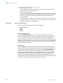
Color tab
The appearance of the lamp can be configured in the COLOR tab. The operating modes
described in chapter 3.4 are available. Configuration is done by selecting the different
options such as color, light pattern and frequency from the CONFIGURATION OF COLOR
OPERATION 8
8026183 / 2021-04-29 | SICK
Subject to change without notice
15

area on the left. After the desired option has been activated by clicking on it, it can be
transferred to the SLT in the preview in the center area of the page by clicking again
in the desired segment. Operating mode-specific functions are available for selection in
the area on the right. In the center part of the tab, the corresponding configurations are
displayed as previews. The colors and icons signal how each segment is configured.
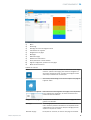
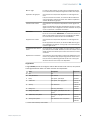
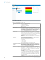
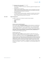
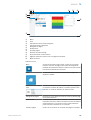
Figure 1: Color tab
Table 3: Functions of the COLOR tab
Operating mode selection Selection of operating mode:
- Signal lamp mode
- Filling level mode
- Animation mode
Color palette A color palette with 21 different colors is available.
In Signal lamp mode, 7 colors are available in the preselection.
Another color can be added by clicking the button with the plus
sign. By clicking on the desired color, it can be transferred to the
layout at the corresponding position.
Light pattern Four different light patterns are available: Continuous light, flash‐
ing, strobe, pulsating. The illuminated images can be activated by
clicking on them. You can see this with the blue coloring of the
selected button.
The selected light pattern is transferred by clicking on the individ‐
ual segment in the layout.
Frequency The frequency of the flashing, strobing or pulsating light patterns
can also be set.
The following frequencies are available:
- Slow (0.5 Hz)
- Medium (1.5 Hz)
- Fast (2.0 Hz)
The activated frequency is marked in blue.
Switch-on behavior of LEDs This selection is available in Filling level and Animation mode.
A selection is made to determine whether the LEDs turn on from
the bottom end of the SLT upwards (bottom up) or from the top
end downwards (top down).
Segment representation This selection is available in Filling level and Animation mode.
It is defined whether the LEDs should change color or light pattern
as soon as the LED segment above them begins to glow. There are
three options here:
- The previously activated segments retain their light animation.
8 OPERATION
16
8026183 / 2021-04-29 | SICK
Subject to change without notice

- The segments that are already illuminated stop their light pattern
animation as soon as a new segment is added, but remain acti‐
vated. Only the uppermost segment shows an animation.
- All segments show the light pattern of the uppermost segment
Layout The layout shows a preview of the configuration of the SLT. The
colors and icons symbolize how the lamp will look later.
Group separation This function is only available in Signal lamp mode.
Activating the function turns off one LED segment between the
groups. This allows for better visual separation of the individual
groups.
Transfer values This selection is only available in Signal lamp mode.
After changing the size of the individual groups in Signal lamp
mode, this configuration must be transferred to the SLT by clicking
the “Transfer values” button.
Reset This selection is available in Signal lamp and Filling level mode.
Clicking on the RESET button resets the number of LED segments
in Signal lamp mode to the presetting. The limit values are reset in
Filling level mode.
Delete values This function is only available in Signal lamp mode.
By deleting the values, the number of LEDs in the changeable
groups is set to 0 and group 1 is then automatically set to 20.
Configuration of limit val‐
ues
In Filling level mode, a value between 0 and 100% can be set for
each LED segment. It is important to note that the value in each
LED segment may not be higher than the value in the segment
above it.
Animation repetition This selection can be used to set the repetition pattern of the
animation. The Loop (always building up from bottom to top) and
Bounce (first building up from bottom to top, then going down
from top to bottom) properties are available.
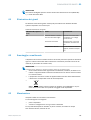
Buzzer tab
The SLB alarm unit can be configured in the BUZZER tab. In addition to the volume,
various sound effects can also be set. The following sound effects are available:
Sound effect Description Frequency
1 Off Off
2 Continuous tone Continuous tone 3,378 Hz
3 Beeping Fast, periodic tone 3,378 Hz
4 Whistling Fast, high/low tone 2,016 Hz &
3,012 Hz
5 Sweep Sweeping tone 1,000 Hz &
4,032 Hz
6 Beeping, slowly Slow, periodic tone 3,378 Hz
7 Beeping, with pause Fast, periodic tone with pause
1)
3,378 Hz
8 Whistling, with pause Fast, high/low tone with pause
1)
2,016 Hz &
3,012 Hz
9 Sweep, with pause Sweeping tone with pause
1)
1,000 Hz &
4,032 Hz
1)
Pause: 500 ms on / 500 ms off
OPERATION 8
8026183 / 2021-04-29 | SICK
Subject to change without notice
17

Alarm tab
Three user-defined light patterns (profile 1 to 3) can be configured in the ALARM tab. For
this purpose, an individual color sample can be created after selecting one of the three
profiles. The selection of patterns is done as with the regular color selection in the Color
tab. These three profiles can be selected for display on the STATUS page in all three
operating modes:
•
Diagnostics page
The current status of the SLT can be checked on the Diagnostics page. If the
device reports an error, it will be displayed here. The sending of IO-Link events can
also be deactivated here.
•
Identification page
The device identification details are displayed on the Identification page. An appli‐
cation-specific name and a device function name can be specified here.
•
Settings page
The language of the user interface can be selected on the SETTINGS page.
8.2.1.2.3 Diagnostics page
The current status of the SLT can be checked on the Diagnostics page. If the device
reports an error, it will be displayed here. The sending of IO-Link events can also be
deactivated here.
8.2.1.2.4 Identification page
The device identification details are displayed on the Identification page. An applica‐
tion-specific name and a device function name can be specified here.
8.2.1.2.5 Settings page
The language of the user interface can be selected on the Settings page.
The following settings are possible:
•
Language: English/Englisch, German/Deutsch
Use the INFORMATION button to get more detailed information about the version of the
interface software.
8.2.1.3 Configuration via IO-Link master based on the IODD
Instead of the SiLink2 IO-Link master, other IO-Link masters can also be used to
configure the SLT. For example, the SIG200 IO-Link master (available at www.sick.com)
enables the use of a graphical user interface generated from the IODD (IO-Link device
description file) of the SLT. No SDD is necessary here, because the configuration is
done directly via the parameters described in the IODD. For more information on the
procedure, please refer to the SIG200 User Manual, which can also be downloaded at
www.sick.com.
8.2.1.4 Configuration via direct access to service and process data
The third option for configuring the SLT is to directly access the service and process
data via an IO-Link master or a PLC with a connected IO-Link master terminal without
using a graphical user interface. When using this type of configuration/control, informa‐
tion about the process data structure for control and service data (ISDUs) is required for
configuration.
NOTE
Detailed information can be found in the IO-Link description (8026795) and / or the
IODD description.
8 OPERATION
18
8026183 / 2021-04-29 | SICK
Subject to change without notice

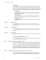
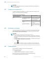
9 Troubleshooting
The Troubleshooting table indicates which measures are to be taken if the device stops
working.
Table 4: Troubleshooting
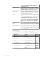
LED indicator/fault pattern Cause Measures
Off No voltage or voltage below
the limit values
Check the power supply,
check all electrical connec‐
tions (cables and plug connec‐
tions)
Voltage interruptions Ensure there is a stable power
supply without interruptions
Device is defective If the voltage supply is OK,
replace the device
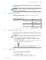
10 Disassembly and disposal
The device must be disposed of in line with applicable country-specific regulations.
When disposing of them, you should try to recycle them (especially the precious met‐
als).
NOTE
Disposal of batteries, electrical and electronic devices
•
In accordance with international regulations, batteries, rechargeable batteries and
electrical and electronic devices must not be disposed of with household waste.
•
The owner is required by law to dispose of these devices at the appropriate public
collection points at the end of their service life.
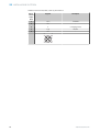
•
WEEE: This symbol on the product, its packaging or in the document
indicates that a product is subject to the specified regulations.
11 Maintenance
SICK devices are maintenance-free.
We do, however, recommend that the following activities are undertaken regularly:
•
Clean the device
•
Check the fittings and plug connectors
Use a soft cloth moistened with water to clean the device.
Do not use thinners, gasoline or oil.
In case of failure or damage of the SLT caused by aggressive media, no claims for
defects can be asserted.
No modifications may be made to devices.
Subject to change without notice. Specified product properties and technical data are
not written guarantees.
TROUBLESHOOTING 9
8026183 / 2021-04-29 | SICK
Subject to change without notice
19

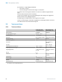
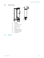
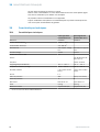
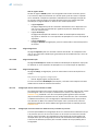
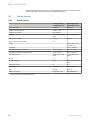
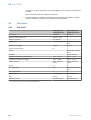
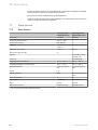
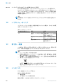
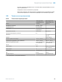
12 Technical data
12.1 Technical specifications
Smart Light Tower
SLT060-0B010J700
Smart Light Buzzer
SLB060-0B010K700
Part number 6075938 6076072
Supply voltage U
B
DC 18 V ... 30 V -
Current consumption Max. 300 mA
1)
-
Connection M12, 5-pin, A-coded Proprietary connection
Mounting direction Upright Upright
Number of LED segments 20 -
Volume - Typ. 88 dB (at 1 m dis‐
tance)
Frequency - 1,000 - 4,032 Hz
Ambient temperature, operation -25 °C … +50 °C -20 °C … +50 °C
Ambient temperature, storage -30 ℃ … +60 ℃ -20 °C … +50 °C
Ambient humidity ≤ 90% (non-condens‐
ing)
≤ 90% (non-condens‐
ing)
IO-Link 1.1 -
Enclosure rating IP65 IP65 (in mounted state)
Protection class III III
Dimensions 281 x Ø 60 mm 53.5 x Ø 60 mm
Weight 0.54 kg 0.06 kg
Housing material Polycarbonate (PC) Polycarbonate (PC)
1)
Including accessories for beeper SLB060-0B010K700
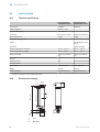
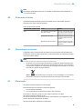
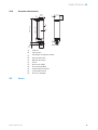
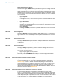
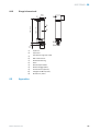
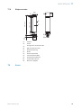
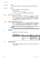
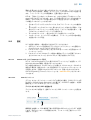
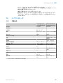
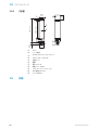
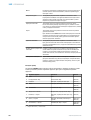
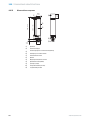
12.2 Dimensional drawings
1
4
5
5
6
7
2
3
8
9
ß
à
Ø 60
(2.36)
Ø 52
(2.03)
281 (11.06)
201.5 (7.93)
25
(0.98)
53.5
(2.11)
1
Cover
2
Main body
12 TECHNICAL DATA
20
8026183 / 2021-04-29 | SICK
Subject to change without notice
Seite wird geladen ...
Seite wird geladen ...
Seite wird geladen ...
Seite wird geladen ...
Seite wird geladen ...
Seite wird geladen ...
Seite wird geladen ...
Seite wird geladen ...
Seite wird geladen ...
Seite wird geladen ...
Seite wird geladen ...
Seite wird geladen ...
Seite wird geladen ...
Seite wird geladen ...
Seite wird geladen ...
Seite wird geladen ...
Seite wird geladen ...
Seite wird geladen ...
Seite wird geladen ...
Seite wird geladen ...
Seite wird geladen ...
Seite wird geladen ...
Seite wird geladen ...
Seite wird geladen ...
Seite wird geladen ...
Seite wird geladen ...
Seite wird geladen ...
Seite wird geladen ...
Seite wird geladen ...
Seite wird geladen ...
Seite wird geladen ...
Seite wird geladen ...
Seite wird geladen ...
Seite wird geladen ...
Seite wird geladen ...
Seite wird geladen ...
Seite wird geladen ...
Seite wird geladen ...
Seite wird geladen ...
Seite wird geladen ...
Seite wird geladen ...
Seite wird geladen ...
Seite wird geladen ...
Seite wird geladen ...
Seite wird geladen ...
Seite wird geladen ...
Seite wird geladen ...
Seite wird geladen ...
Seite wird geladen ...
Seite wird geladen ...
Seite wird geladen ...
Seite wird geladen ...
Seite wird geladen ...
Seite wird geladen ...
Seite wird geladen ...
Seite wird geladen ...
Seite wird geladen ...
Seite wird geladen ...
Seite wird geladen ...
Seite wird geladen ...
Seite wird geladen ...
Seite wird geladen ...
Seite wird geladen ...
Seite wird geladen ...
Seite wird geladen ...
Seite wird geladen ...
Seite wird geladen ...
Seite wird geladen ...
Seite wird geladen ...
Seite wird geladen ...
Seite wird geladen ...
Seite wird geladen ...
Seite wird geladen ...
Seite wird geladen ...
Seite wird geladen ...
Seite wird geladen ...
Seite wird geladen ...
Seite wird geladen ...
Seite wird geladen ...
Seite wird geladen ...
Seite wird geladen ...
Seite wird geladen ...
Seite wird geladen ...
Seite wird geladen ...
Seite wird geladen ...
Seite wird geladen ...
Seite wird geladen ...
Seite wird geladen ...
Seite wird geladen ...
Seite wird geladen ...
Seite wird geladen ...
Seite wird geladen ...
Seite wird geladen ...
Seite wird geladen ...
Seite wird geladen ...
Seite wird geladen ...
Seite wird geladen ...
Seite wird geladen ...
Seite wird geladen ...
Seite wird geladen ...
Seite wird geladen ...
Seite wird geladen ...
Seite wird geladen ...
Seite wird geladen ...
Seite wird geladen ...
Seite wird geladen ...
Seite wird geladen ...
Seite wird geladen ...
Seite wird geladen ...
Seite wird geladen ...
Seite wird geladen ...
Seite wird geladen ...
Seite wird geladen ...
Seite wird geladen ...
Seite wird geladen ...
Seite wird geladen ...
Seite wird geladen ...
Seite wird geladen ...
Seite wird geladen ...
Seite wird geladen ...
Seite wird geladen ...
Seite wird geladen ...
Seite wird geladen ...
Seite wird geladen ...
Seite wird geladen ...
Seite wird geladen ...
Seite wird geladen ...
Seite wird geladen ...
Seite wird geladen ...
Seite wird geladen ...
Seite wird geladen ...
Seite wird geladen ...
Seite wird geladen ...
Seite wird geladen ...
Seite wird geladen ...
Seite wird geladen ...
Seite wird geladen ...
Seite wird geladen ...
Seite wird geladen ...
Seite wird geladen ...
Seite wird geladen ...
Seite wird geladen ...
Seite wird geladen ...
Seite wird geladen ...
Seite wird geladen ...
Seite wird geladen ...
Seite wird geladen ...
Seite wird geladen ...
Seite wird geladen ...
Seite wird geladen ...
Seite wird geladen ...
Seite wird geladen ...
Seite wird geladen ...
Seite wird geladen ...
Seite wird geladen ...
Seite wird geladen ...
Seite wird geladen ...
Seite wird geladen ...
Seite wird geladen ...
Seite wird geladen ...
Seite wird geladen ...
Seite wird geladen ...
Seite wird geladen ...
Seite wird geladen ...
Seite wird geladen ...
Seite wird geladen ...
Seite wird geladen ...
Seite wird geladen ...
Seite wird geladen ...
Seite wird geladen ...
Seite wird geladen ...
Seite wird geladen ...
Seite wird geladen ...
-
 1
1
-
 2
2
-
 3
3
-
 4
4
-
 5
5
-
 6
6
-
 7
7
-
 8
8
-
 9
9
-
 10
10
-
 11
11
-
 12
12
-
 13
13
-
 14
14
-
 15
15
-
 16
16
-
 17
17
-
 18
18
-
 19
19
-
 20
20
-
 21
21
-
 22
22
-
 23
23
-
 24
24
-
 25
25
-
 26
26
-
 27
27
-
 28
28
-
 29
29
-
 30
30
-
 31
31
-
 32
32
-
 33
33
-
 34
34
-
 35
35
-
 36
36
-
 37
37
-
 38
38
-
 39
39
-
 40
40
-
 41
41
-
 42
42
-
 43
43
-
 44
44
-
 45
45
-
 46
46
-
 47
47
-
 48
48
-
 49
49
-
 50
50
-
 51
51
-
 52
52
-
 53
53
-
 54
54
-
 55
55
-
 56
56
-
 57
57
-
 58
58
-
 59
59
-
 60
60
-
 61
61
-
 62
62
-
 63
63
-
 64
64
-
 65
65
-
 66
66
-
 67
67
-
 68
68
-
 69
69
-
 70
70
-
 71
71
-
 72
72
-
 73
73
-
 74
74
-
 75
75
-
 76
76
-
 77
77
-
 78
78
-
 79
79
-
 80
80
-
 81
81
-
 82
82
-
 83
83
-
 84
84
-
 85
85
-
 86
86
-
 87
87
-
 88
88
-
 89
89
-
 90
90
-
 91
91
-
 92
92
-
 93
93
-
 94
94
-
 95
95
-
 96
96
-
 97
97
-
 98
98
-
 99
99
-
 100
100
-
 101
101
-
 102
102
-
 103
103
-
 104
104
-
 105
105
-
 106
106
-
 107
107
-
 108
108
-
 109
109
-
 110
110
-
 111
111
-
 112
112
-
 113
113
-
 114
114
-
 115
115
-
 116
116
-
 117
117
-
 118
118
-
 119
119
-
 120
120
-
 121
121
-
 122
122
-
 123
123
-
 124
124
-
 125
125
-
 126
126
-
 127
127
-
 128
128
-
 129
129
-
 130
130
-
 131
131
-
 132
132
-
 133
133
-
 134
134
-
 135
135
-
 136
136
-
 137
137
-
 138
138
-
 139
139
-
 140
140
-
 141
141
-
 142
142
-
 143
143
-
 144
144
-
 145
145
-
 146
146
-
 147
147
-
 148
148
-
 149
149
-
 150
150
-
 151
151
-
 152
152
-
 153
153
-
 154
154
-
 155
155
-
 156
156
-
 157
157
-
 158
158
-
 159
159
-
 160
160
-
 161
161
-
 162
162
-
 163
163
-
 164
164
-
 165
165
-
 166
166
-
 167
167
-
 168
168
-
 169
169
-
 170
170
-
 171
171
-
 172
172
-
 173
173
-
 174
174
-
 175
175
-
 176
176
-
 177
177
-
 178
178
-
 179
179
-
 180
180
-
 181
181
-
 182
182
-
 183
183
-
 184
184
-
 185
185
-
 186
186
-
 187
187
-
 188
188
-
 189
189
-
 190
190
-
 191
191
-
 192
192
-
 193
193


SICK SLT Smart Light Tower Bedienungsanleitung
- Typ
- Bedienungsanleitung
in anderen Sprachen
- English: SICK SLT Smart Light Tower Operating instructions
- français: SICK SLT Smart Light Tower Mode d'emploi
- español: SICK SLT Smart Light Tower Instrucciones de operación
- italiano: SICK SLT Smart Light Tower Istruzioni per l'uso
- русский: SICK SLT Smart Light Tower Инструкция по эксплуатации
- português: SICK SLT Smart Light Tower Instruções de operação
- 日本語: SICK SLT Smart Light Tower 取扱説明書