Extraflame 1P Hydraulic system separator kit Bedienungsanleitung
- Kategorie
- Messen, Testen
- Typ
- Bedienungsanleitung

KIT SEPARATORE IMPIANTO IDRAULICO 1P
HYDRAULIC SYSTEM SEPARATOR KIT 1P
KIT SÉPARATEUR INSTALLATION HYDRAULIQUE 1P
ZURÜSTSATZ TRENNVORRICHTUNG HYDRAULIKANLAGE 1P
KIT SEPARADOR DE LA INSTALACIÓN HIDRÁULICA 1P
004276585 – 004

2

3
ITALIANO .......................................................................................................................................................................................................... 4
SpecIfIche TecNIche .................................................................................................................................................................................... 4
AvverTeNze e SIcUrezzA ............................................................................................................................................................................ 5
KIT SepArATOre IMpIANTO IDrAULIcO ...................................................................................................................................................... 6
LeGeNDA ScheDA ........................................................................................................................................................................................... 6
cONNeSSIONe DeLLA ScheDA AL GeNerATOre A peLLeT eD ALLA cALDAIA AUSILIArIA ................................................................. 7
DISpLAY e STrUTTUrA MeNU ........................................................................................................................................................................ 9
fUNzIONAMeNTO ......................................................................................................................................................................................... 10
ALLArMI e vISUALIzzAzIONI ...................................................................................................................................................................... 10
fUNzIONI vArIe ............................................................................................................................................................................................. 11
ANTIBLOCCAGGIO POMPA : .................................................................................................................................................................................................................11
SCARICO ARIA : ..........................................................................................................................................................................................................................................11
SMALTIMeNTO ............................................................................................................................................................................................... 11
eNGLISh .......................................................................................................................................................................................................... 12
TechNIcAL SpecIfIcATIONS ....................................................................................................................................................................... 12
WArNINGS AND SAfeTY ............................................................................................................................................................................... 13
hYDrAULIc SYSTeM SepArATOr KIT ......................................................................................................................................................... 14
BOArD KeY ..................................................................................................................................................................................................... 14
BOArD cONNecTION TO The peLLeT heAT GeNerATOr AND TO The AUXILIArY BOILer ................................................................. 15
DISpLAY AND MeNU STrUcTUre ................................................................................................................................................................ 17
OperATION ..................................................................................................................................................................................................... 18
ALArMS AND DISpLAYS ................................................................................................................................................................................ 18
vArIOUS fUNcTIONS .................................................................................................................................................................................... 19
PUMP ANTILOCK: .....................................................................................................................................................................................................................................19
AIR DISCHARGE: ........................................................................................................................................................................................................................................19
DISpOSAL........................................................................................................................................................................................................ 19
frANÇAIS ....................................................................................................................................................................................................... 20
SpécIfIcATIONS TechNIqUeS ..................................................................................................................................................................... 20
MISeS eN GArDe eT SécUrITé ..................................................................................................................................................................... 21
KIT SépArATeUr INSTALLATION hYDrAULIqUe ...................................................................................................................................... 22
LéGeNDe De LA cArTe ................................................................................................................................................................................. 22
cONNeXION De LA cArTe AU GéNérATeUr À peLLeT eT À LA chAUDIÈre AUXILIAIre .................................................................... 23
DISpLAY eT STrUcTUre DU MeNU ............................................................................................................................................................. 25
fONcTIONNeMeNT ....................................................................................................................................................................................... 26
ALArMeS eT AffIchAGeS ............................................................................................................................................................................ 26
fONcTIONS DIverSeS ................................................................................................................................................................................. 27
ANTIBLOCAGE DE LA POMPE ..............................................................................................................................................................................................................27
ÉVACUATION DE L'AIR: ...........................................................................................................................................................................................................................27
éLIMINATION .................................................................................................................................................................................................. 27
DeUTSch ......................................................................................................................................................................................................... 28
TechNISche DATeN ...................................................................................................................................................................................... 28
SIcherheITShINWeISe ................................................................................................................................................................................. 29
zUrÜSTSATz TreNNvOrrIchTUNG hYDrAULIKANLAGe ...................................................................................................................... 30
KArTeNLeGeNDe .......................................................................................................................................................................................... 30
verBINDUNG Der KArTe AN DeN peLLeTWÄrMeerzeUGer UND AN DeN zUSATzKeSSeL ............................................................. 31
DISpLAY UND MeNÜSTrUKTUr ................................................................................................................................................................... 33
BeTrIeB: .......................................................................................................................................................................................................... 34
ALArMe UND ANzeIGeN .............................................................................................................................................................................. 34
DIverSe fUNKTIONeN .................................................................................................................................................................................. 35
ANTIBLOCKIERFUNKTION DER PUMPE ...........................................................................................................................................................................................35
LUFTABLASS: ..............................................................................................................................................................................................................................................35
BeSeITIGUNG ................................................................................................................................................................................................. 35
eSpAÑOL ......................................................................................................................................................................................................... 36
eSpecIfIcAcIONeS TecNIcAS ..................................................................................................................................................................... 36
ADverTeNcIAS Y SeGUrIDAD ..................................................................................................................................................................... 37
KIT SepArADOr De LA INSTALAcIÓN hIDrÁULIcA .................................................................................................................................. 38
LeYeNDA De LA TArJeTA .............................................................................................................................................................................. 38
cONeXIÓN De LA TArJeTA AL GeNerADOr De peLLeT Y A LA cALDerA AUXILIAr ............................................................................ 39
pANTALLA Y eSTrUcTUrA DeL MeNú ........................................................................................................................................................ 41
fUNcIONAMIeNTO ........................................................................................................................................................................................ 42
ALArMAS Y vISUALIzAcIONeS .................................................................................................................................................................... 42
fUNcIONeS vArIAS ....................................................................................................................................................................................... 43
ANTIBLOQUEO DE LA BOMBA: ...........................................................................................................................................................................................................43
DESCARGA AIRE: .......................................................................................................................................................................................................................................43
eLIMINAcIÓN ................................................................................................................................................................................................. 43

500
40 60 120 60 170
100
60
160
3/4"M
3/4"M
3/4"M 3/4"M
450
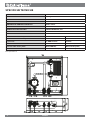
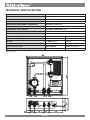
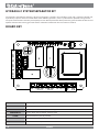
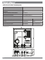
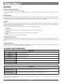
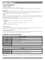
SPECIFICHE TECNICHE
DIMENSIONI L X P X H 450X160X500 mm
PESO 12,6 kg
POSIZIONE DI MONTAGGIO Verticale
GRADO DI PROTEZIONE IN VERSIONE CON CONNETTORE IP40
TEMPERATURA AMBIENTE OPERATIVA DA 0°C A 60°C
TEMPERATURA DI IMMAGAZZINAMENTO DA 10°C A +60°C
UMIDITÀ RELATIVA MASSIMA SENZA CONDENSA 95%
Tensione di alimentazione 230Vac 50/60 Hz
Potenza massima assorbita 60W Max
Sonda H2O ritorno stufa a pellet I1 / GND NTC 10 k
Sonda H2O mandata stufa a pellet I2 / GND NTC 10 k
Ingresso T.A. I3 / GND Contatto Contatto
Uscita circolatore OUT1 / N 230Vac (RELE)
Comando STBY stufa a pellet OUT2(COM-NO) RELE(contatto pulito)
Comando AUX OUT3(NA-COM-NO) RELE(contatto pulito)
Il kit Separatore 1P
ITALIANO
4
ITALIANO

ITALIANO
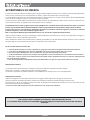
AVVERTENZE E SICUREZZA
Il presente manuale di istruzione costituisce parte integrante del prodotto: assicurarsi che sia sempre a corredo dell’apparecchio,
anche in caso di cessione ad un altro proprietario o utente, oppure di trasferimento su un altro luogo.
In caso di suo danneggiamento o smarrimento richiedere un altro esemplare al servizio tecnico di zona. Questo prodotto dev’
essere destinato all’uso per il quale è stato espressamente realizzato.
E’ esclusa qualsiasi responsabilità contrattuale ed extracontrattuale del costruttore per danni causati a persone, animali o cose,
da errori d’installazione, di regolazione di manutenzione e da usi impropri.
L’installazione deve essere eseguita da personale qualicato e/o assistenza tecnica del costruttore, il quale si assumerà
l’intera responsabilità dell’installazione denitiva e del conseguente buon funzionamento del prodotto installato.
E’ necessario tenere in considerazione anche tutte le leggi e le normative nazionali, regionali, provinciali e comunali
presente nel paese in cui è stato installato l’apparecchio.
Non vi sarà responsabilità da parte del fabbricante in caso di mancato rispetto di tali precauzioni.
Dopo aver tolto l’imballo, assicurarsi dell’integrità e della completezza del contenuto. In caso di non rispondenza, rivolgersi al
rivenditore da cui è stato acquistato l’apparecchio.
Tutti i componenti elettrici che costituiscono il prodotto garantendone il corretto funzionamento, dovranno essere sostituiti
con pezzi originali esclusivamente da un centro di assistenza tecnica autorizzato.
Per la sicurezza è bene ricordare che:
Prima di eettuare qualsiasi lavoro sull’impianto, spegnere l’interrutore principale dell’alimentazione elettrica.
E’ vietato l’uso dell’apparecchio da parte di bambini o di persone diversamente abili non assistite.
Non toccare parti dell’impianto se si è a piedi nudi e con parti del corpo bagnate o umide.
E’ vietato modicare i dispositivi di sicurezza o di regolazione senza l’autorizzazione o le indicazioni del costruttore.
Non tirare, staccare, torcere i cavi elettrici fuoriuscenti dalla scheda supplementare anche se questa è scollegata dalla
rete di alimentazione elettrica.
Non lasciare gli elementi dell’imballo alla portata dei bambini o di persone diversamente abili non assistite.
Collegamento elettrico
La centralina dovrà essere installata e collegata da personale abilitato secondo le normative vigenti.
Alimentare la centralina a 230 V 50 Hz tramite interruttore bipolare.
La centralina è protetta con fusibile rapido da 3.15 A. Eettuare una corretta messa a terra del dispositivo.
Collegamento idraulico
Dopo aver collegato il kit separatore provvedere al serraggio di tutte le ghiere di ssaggio dei tubi di rame.
Prestare particolare attenzione quando si collega il kit all’impianto idraulico, evitando di piegare i tubi di rame.
Per contrastare la forza di serraggio esercitata sul tubo di collegamento dell’impianto idraulico usare una chiave ssa o altro
utensile sul terminale del kit separatore.
> Durante lo sato dell’aria porre la massima attenzione a non bagnare la centralina.
PER IL RISPETTO DELLE NORME DI SICUREZZA È OBBLIGATORIO INSTALLARE
E UTILIZZARE I NOSTRI PRODOTTI SEGUENDO SCRUPOLOSAMENTE LE INDICAZIONI FORNITE NEL PRESENTE
MANUALE.
5
ITALIANO

NO
OUT1
COM
OUT2
NO COM
OUT3
NC
I1 GND I2 GND I3 GND
F N
N
ITALIANO
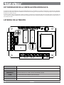
N F Neutro e fase
OUT1 N Uscita 230V 50 Hz circolatore impianto
COM NO/OUT2 Uscita contatto STBY termostufa a pellet normalmente aperto
COM NO/OUT3 Uscita contatto caldaia ausiliaria normalmente aperto
I3 GND Ingresso termostato ambiente (contatto pulito)
I2 GND Ingresso sonda NTC mandata termostufa a pellet
I1 GND Ingresso sonda NTC ritorno termostufa a pellet
KIT SEPARATORE IMPIANTO IDRAULICO
Il gruppo di separazione idraulica completo di scambiatore a piastre, circolatore nel circuito secondario e centralina di regolazione,
consente di separare idraulicamente i uidi termovettori di due generatori diversi, come ad esempio il termoprodotto a pellet
e la caldaia a gas.
Lo speciale controllo del circolatore del circuito secondario garantisce un'ecace protezione dalla condensa del generatore di
calore a pellet e la gestione ottimizzata del contatto del generatore ausiliario permette di ottenere l'automatismo nel passaggio
da una all'altra fonte di calore.
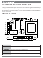
LEGENDA SCHEDA
6
ITALIANO

R
MT
STBY
VE
VSP
TA
R
CA
OUT3
SF SF
OUT1
I1
I2
OUT2
I3
NO
F N
OUT1
N
COM
OUT2
NO COM
OUT3
NC
I1 GND I2 GND I3 GND
ITALIANO
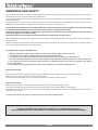
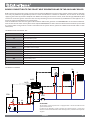
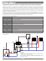
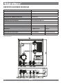
CA Caldaia ausiliaria
I1 Sonda ritorno termostufa a pellet
I2 Sonda mandata termostufa a pellet
I3 Ingresso termostato ambiente
M Manometro
OUT1 Uscita circolatore impianto
OUT2 Uscita contatto STBY termostufa
OUT3 Uscita contatto caldaia ausiliaria
R Radiatori
SF Sato
STBY Ingresso contatto di accensione termostufa a pellet
VSP Valvola sicurezza a pressione
T Termometro
TA Termostato ambiente
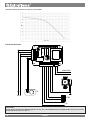
CONNESSIONE DELLA SCHEDA AL GENERATORE A PELLET ED ALLA CALDAIA AUSILIARIA
Prima di iniziare qualsiasi lavoro sull’impianto spegnere l’interruttore principale. I lavori sull’impianto di riscaldamento e l’
installazione elettrica devono essere eseguiti esclusivamente da personale qualicato e/o assistenza tecnica del costruttore.
Inoltre devono essere rispettate le direttive dell’ ente per l’erogazione dell’elettricità. Prima del collegamento alla corrente elettrica
vericare il voltaggio (230V/50 Hz). Installazione mal eseguite possono essere pericolose e portano all’annullamento della
garanzia. Evitare qualsiasi modica dell’apparecchio in quanto può avere conseguenze negative sulla sicurezza dell’impianto.
Collegare la scheda alla termostufa tramite due cavetti fra STBY sul generatore e COM NO/OUT2 nella scheda della centralina.
Collegare il contatto della caldaia ausiliaria CA all’uscita COM NO/OUT3 e il contatto del termostato ambiente TA all’ingresso I3
GND contatto pulito. Dopo aver eettuato i collegamenti elettrici ai dispositivi dell’impianto alimentare tramite due cavetti la
scheda con 230 V (F-N).
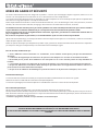
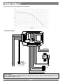
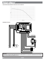
LEGENDA SCHEMA IDRAULICO ED ELETTRICO
SCHEMA IDRAULICO
ATTENZIONE!
Il kit separatore impianto idraulico è dotato di una valvola di ritegno posta nel
ramo di ritorno impianto.
Per il corretto funzionamento kit separatore impianto idraulico è necessario
installare una valvola di ritegno nella mandata della caldaia ausiliaria, come
riportato nello schema idraulico.
7
ITALIANO

NO
OUT1
COM
OUT2
NO COM
OUT3
NC
I1 GND I2 GND I3 GND
F N
N
STBY
CA
230V/50Hz
N
TA
ITALIANO
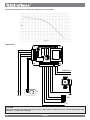
SCHEMA ELETTRICO
ATTENZIONE:
DOPO L’INSTALLAZIONE E COLLEGAMENTO DEL KIT, IMPOSTARE IL SET ACQUA DEL TERMOPRODOTTO/ CALDAIA A
PELLET EXTRAFLAME ALMENO A 70/75°C.
CURVA PREVALENZA RESIDUA CIRCUITO DI RISCALDAMENTO
8
ITALIANO

MENU
!
MENU
!
MENU
!
MENU
!
MENU
!
MENU
!
MENU
!
MENU
!
MENU
!
MENU
!
MENU
!
MENU
!
MENU
!
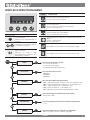
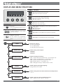
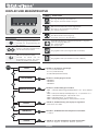
TASTO FUNZIONE
MENU
!
Premendo per 3 secondi il tasto si
accede nel menu.
All’interno della programmazione fa
da “Enter”.
MENU
!
MENU
!
Consente di scorrere all’interno dei menu
e/
o modicare i parametri
MENU
!
Consente di attivare (ON) o disattivare
(OFF) la centralina.
All’interno dei menu e della
programmazione premendo si esce
dalla funzione o SET (Esc).
ICONA SIGNIFICATO
MENU
!
Accesa: indica la presenza di un allarme
Spenta : indica l’assenza di allarmi
MENU
!
Indica quando è attivo il ritardo accensione AUX. In stato OFF la
spia è sempre spenta
Accesa: indica che il ritardo sta decrementando
Spenta : ritardo uguale a 0
MENU
!
Indica lo stato del termostato ambiente TA
Spenta : Contatto aperto / TA soddisfatto
Accesa : Contatto chiuso / TA in richiesta
MENU
!
Spia pompa 1(icona circolatore 1): segnala lo stato dell’uscita
OUT_1
Spenta : pompa disattiva
Accesa : pompa attiva
MENU
!
Uscita OUT 2 attiva (è in funzione il termoprodotto STBY)
MENU
!
Uscita OUT 3 attiva (è in funzione la Caldaia ausiliaria CA)
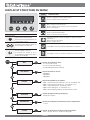
DISPLAY E STRUTTURA MENU
TEST USCITE
STATO
LINGUA
Consente di impostare una delle lingue disponibili:
Italiano - Inglese - Francese - Tedesco - Spagnolo.
Consente di visualizzare gli stati:
- I1= xx °C (sonda ritorno)
- I2= xx °C (sonda mandata)
- I3= ON / OFF (termostato ambiente)
Consente di testare le uscite :
- TEST OUT 1
- TEST OUT 2
- TEST OUT 3
TARATURE
FABBRICA
Consente di modicare le impostazioni:
- PR01 = Soglia (attivazione) circolatore 1 (55 – 60 °C) Default = 60°
- PR02 = Delta (spegnimento) circolatore 1 (1 - 5 °C) Default = 5° C
- PR03 = Soglia accensione (58 – 62) Default = 62°C
- PR04 = Delta accensione (1 - 5 °C) Default = 3°C
- PR05 = Ritardo accensione AUX
(0 - 60min) Default = 20 min
DISPLAY
Consente di regolare la illuminazione del display:
- Range da 3 a 100%
TEMPERATURA
Consente di impostare l’unità di misura della temperatura:
- °C o°F
ITALIANO
9
ITALIANO

FUNZIONAMENTO
ACCENSIONE E SPEGNIMENTO
Avvengono tramite pressione prolungata del tasto
.
Lo stato (ON/OFF) verrà visualizzato sul display, le varie visualizzazioni del display sono indicate nella tabella sottostante.
CIRCOLATORE 1
Con dispositivo acceso (ON) il circolatore viene attivato dal regolatore quando la temperatura rilevata dalla sonda I1 supera il
valore impostato PR01. Viene disattivato quando la temperatura rilevata dalla sonda I1 scende al di sotto del valore
impostato SOGLIA OUT1 meno il valore di delta PR02 (Vedi schema idraulico).
LOGICA
Da centralina spenta (alimentata) in o viene gestita solo la caldaia ausiliaria (CA) tramite il termostato ambiente (TA).
Tramite la pressione prolungata di accensione si passa alla fase di attivazione in cui la centralina gestisce il funzionamento-
gestione della caldaia ausiliaria e del termoprodotto.
Le fasi di funzionamento sono 3 così suddivise e visualizzate sul display:
ATTESA:
Il TA è soddisfatto, la CA e il termoprodotto sono spenti - non in funzione.
PELLET:
Il TA è in richiesta è il termoprodotto è in funzione (CA spenta)
AUX:
Il TA è in richiesta è la CA è in funzionamento.
GESTIONE STBY E CA:
Il contatto STBY viene attivato nel momento di richiesta del TA, mentre il contatto CA viene attivato nel momento in cui la
temperatura rilevata del la sonda T2 e inferiore a PR03 e dopo un ritardo modicabile su PR04.
GESTIONE STBY STUFA
Nel caso di collegamento dello STBY sui prodotti Extraame è possibile avere due modalità di funzionamento del termoprodotto,
spegnimento istantaneo o la modulazione. Per maggiori informazioni consultare il manuale utente.
ALLARMI E VISUALIZZAZIONI
VISUALIZZAZIONI
OFF La scheda è nello stato OFF
ATTESA La scheda è nello stato di funzionamento
PELLET E’ attiva la stufa a biomassa
AUX E’ attiva l’uscita ausiliaria
ANTIBLOCCO E’ attiva la funzione antibloccaggio pompa
SCARICO ARIA E’ attiva la funzione scarico aria.
ALLARMI
ALLARME SONDA I1 Avviene quando la sonda “I1” si guasta, a display “-------”.
ALLARME SONDA I2 Avviene quando la sonda “I2” si guasta, a display “-------”.
Nota: In caso di un allarme da parte del Kit separatore idraulico, viene gestita solo la caldaia Ausiliaria, (CA) tramite il termostato
ambiente (TA).
ITALIANO
10
ITALIANO

FUNZIONI VARIE
ANTIBLOCCAGGIO POMPA :
Se la centralina rimane nello stato di OFF per 96 ore consecutive in automatico si attiva l’uscita OUT1 per un tempo pari a 30
secondi. Questa funzione viene utilizzata per evitare il bloccaggio delle pompe nel caso di prolungato inutilizzo. Durante il ciclo
antibloccaggio pompe sul display viene visualizzata la scritta “ANTIBLOCCO”.
SCARICO ARIA :
Questa funzione permette di eettuare le operazioni di sato dell’impianto con centralina in OFF. Se viene attivata la funzione
l’uscita OUT1 lavorerà ad impulsi intervallando 30 secondi di lavoro con 30 secondi di pausa. Durante la funzione scarico aria sul
display viene visualizzata la scritta “SCARICO ARIA”. Per attivare la funzione premere contemporaneamente i tasti
+
per
5 secondi, per disattivare premere il tasto ON/OFF
.
ITALIANO
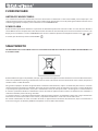
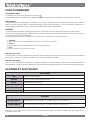
SMALTIMENTO
Questo simbolo che appare sul prodotto, sulle pile, sugli accumulatori oppure sulla loro confezione o sulla loro documentazione,
indica che il prodotto e le pile o gli accumulatori inclusi al termine del ciclo di vita utile non devono essere raccolti, recuperati o
smaltiti assieme ai riuti domestici.
Una gestione impropria dei riuti di apparecchiature elettriche ed elettroniche, di pile o accumulatori può causare il rilascio di
sostanze pericolose contenute nei prodotti. Allo scopo di evitare eventuali danni all’ambiente o alla salute, si invita l’utilizzatore
a separare questa apparecchiatura, e/o le pile o accumulatori inclusi, da altri tipi di riuti e di consegnarla al centro comunale
di raccolta. È possibile richiedere al distributore il ritiro del riuto di apparecchiatura elettrica ed elettronica alle condizioni e
secondo le modalità previste dal D.Lgs. 49/2014.
La raccolta separata e il corretto trattamento delle apparecchiature elettriche ed elettroniche, delle pile e degli accumulatori
favoriscono la conservazione delle risorse naturali, il rispetto dell'ambiente e assicurano la tutela della salute.
Per ulteriori informazioni sui centri di raccolta dei riuti di apparecchiature elettriche ed elettroniche, di pile e accumulatori è
necessario rivolgersi alle Autorità pubbliche competenti al rilascio delle autorizzazioni.
INFORMAZIONI PER LA GESTIONE DI RIFIUTI DI APPARECCHIATURE ELETTRICHE ED ELETTRONICHE CONTENENTI PILE
E ACCUMULATORI
11
ITALIANO

500
40 60 120 60 170
100
60
160
3/4"M
3/4"M
3/4"M 3/4"M
450
TECHNICAL SPECIFICATIONS
DIMENSIONS L X D X H 450X160X500 mm
WEIGHT 12,6 kg
ASSEMBLY POSITION Vertical
PROTECTION RATING IN VERSION WITH CONNECTOR IP40
OPERATIONAL ENVIRONMENT TEMPERATURE BETWEEN 0°C AND 60°C
STORAGE TEMPERATURE BETWEEN 10°C AND +60°C
MAXIMUM RELATIVE HUMIDITY WITHOUT CONDENSATE 95%
Power supply voltage 230Vac 50/60 Hz
Maximum power consumption 60W Max
Pellet stove return H2O probe I1 / GND NTC 10 k
Pellet stove ow H2O probe I2 / GND NTC 10 k
T.A. Input I3 / GND Contact Contact
Pump outlet OUT1 / N 230Vac (RELAY)
Pellet stove STBY control OUT2(COM-NO) RELAY (dry contact)
AUX control OUT3 (NA-COM-NO) RELAY (dry contact)
Separator kit 1P
ENGLISH
12
ITALIANO

ENGLISH
WARNINGS AND SAFETY
This instructions manual is an integral part of the product: make sure that it always accompanies the appliance, even if transferred
to another owner or user, or if transferred to another place.
If it is damaged or lost, request another copy from the area technician. This product is intended for the use for which it has been
purposely designed.
The manufacturer is exempt from any liability, contractual and extracontractual, for injury/damage caused to persons/animals
and objects, due to installation, adjustment and maintenance errors and improper use.
Installation must be performed by qualied sta and/or by the manufacturer's technical sta, who are fully responsible
for the permanent installation and consequent proper operation of the product installed.
One must also bear in mind all laws and national, regional, provincial and town council Standards present in the country
in which the appliance has been installed.
The manufacturer cannot be held responsible for failure to comply with such precautions.
After removing the packaging, ensure that the content is intact and complete. Otherwise, contact the dealer where the appliance
was purchased.
All electric components that make up the product must be replaced with original spare parts exclusively by an authorised after-
sales centre, thus guaranteeing correct functioning.
For safety purposes please remember that:
Before performing any jobs on the system, turn the electric power supply master switch o.
The appliance must not be used by children or unassisted disabled persons.
Do not touch parts of the plant when you are barefoot or when parts of the body are wet or humid.
The safety and adjustment devices must not be modied without the authorisation or indications of the manufacturer.
Do not pull, disconnect, twist electric cables leaving the additional board, even if disconnected from the electric
power supply mains.
Do not leave the packaging elements within reach of children or unassisted disabled persons.
Electrical connection
The control unit must be installed and connected by qualied sta, in compliance with the regulations in force.
Power the control unit at 230 V 50 Hz using a bipolar switch.
The control unit is protected with a 3.15 A fast fuse. The device must be earthed properly.
Hydraulic connection
After having connected the separator kit, clamp all the locking ring nuts of the copper pipes.
Take special care while connecting the kit to the hydraulic system and avoid bending the copper pipes.
To counteract the clamping force exerted on the connecting pipe of the hydraulic system, use a spanner or another tool on the
end of the separator kit.
> During the air discharge, please pay attention not to get wet the mother board.
IN ORDER TO COMPLY WITH THE SAFETY STANDARDS, IT IS MANDATORY TO INSTALL
AND USE OUR PRODUCTS BY SCRUPULOUSLY FOLLOWING THE GUIDELINES GIVEN IN THIS MANUAL.
13
ITALIANO

HYDRAULIC SYSTEM SEPARATOR KIT
The hydraulic separation kit, featuring a plate heat exchanger, a pump in the secondary circuit and a regulating control unit,
hydraulically separates the heat transfer uids of two dierent generators, such as a pellet thermo-product and a gas boiler.
The special control of the secondary circuit pump ensures ecient protection of the pellet heat generator from condensate and
optimal control of the auxiliary generator enables automatic transfer from one heat source to another.
BOARD KEY
NO
OUT1
COM
OUT2
NO COM
OUT3
NC
I1 GND I2 GND I3 GND
F N
N
ENGLISH
N P Neutral and phase
OUT1 N System pump 230V 50 Hz output
COM NO/OUT2 Pellet stove STBY contact output, normally open
COM NO/OUT3 Auxiliary boiler contact output, normally open
I3 GND Room thermostat input (dry contact)
I2 GND Pellet stove ow NTC probe
I1 GND Pellet stove return NTC probe
14
ITALIANO

R
MT
STBY
VE
VSP
TA
R
CA
OUT3
SF SF
OUT1
I1
I2
OUT2
I3
NO
F N
OUT1
N
COM
OUT2
NO COM
OUT3
NC
I1 GND I2 GND I3 GND
ENGLISH
CA Auxiliary boiler
I1 Pellet stove return probe
I2 Pellet stove ow probe
I3 Room thermostat input
M Pressure Gauge
OUT1 System pump output
OUT2 Stove STBY contact output
OUT3 Auxiliary boiler contact output
R Radiators
SF Venting
STBY Pellet stove ignition contact input
VSP Pressure safety valve
T Thermometer
TA Room thermostat
BOARD CONNECTION TO THE PELLET HEAT GENERATOR AND TO THE AUXILIARY BOILER
Before starting any job on the system, turn the master switch o. Operations on the heating system and the electric installation
must only be performed by qualied personnel and/or manufacturer's technicians. Moreover, the Directives of the body
supplying the electricity must be complied with. Before connecting to the electric current, check the voltage (230V/50 Hz). Bad
installation can be dangerous and lead to the warranty becoming null and void. Avoid any modication to the appliance as it
may have negative consequences on system safety.
Connect the board to the stove using two cables between STBY on the generator and COM NO/OUT2 on the control unit board.
Connect the contact of the auxiliary boiler CA to output COM NO/OUT3 and the contact of room thermostat TA to input I3 GND
dry contact. After having made the electric connections to the system devices, power the additional board with 230 V via two
cables (P-N).
HYDRAULIC AND ELECTRICAL KEY
HYDRAULIC DIAGRAM
ATTENTION!
The hydraulic system separator kit is equipped with a check valve tted in the
system return branch.
In order for the hydraulic system separator kit to work properly, a check valve
must be installed on the ow line of the auxiliary boiler, as shown in the hydraulic
diagram.
15
ITALIANO

NO
OUT1
COM
OUT2
NO COM
OUT3
NC
I1 GND I2 GND I3 GND
F N
N
STBY
CA
230V/50Hz
N
TA
ELECTRICAL DIAGRAM
ENGLISH
ATTENTION :
AFTER INSTALLATION AND CONNECTION OF THE KIT, SET THE TEMPERATURE OF THE WATER OF THE PELLET HYDRO
STOVE/BOILER AT LEAST AT 70/75 ° C.
HEATING CIRCUIT RESIDUAL HYDRAULIC HEAD CURVE
16
ITALIANO

MENU
!
MENU
!
MENU
!
MENU
!
MENU
!
MENU
!
MENU
!
MENU
!
MENU
!
MENU
!
MENU
!
MENU
!
MENU
!
KEY FUNCTION
MENU
!
Press the key for 3 seconds to access
the menu
In the programming mode, it acts as
an “Enter” key.
MENU
!
MENU
!
It enables scrolling the menus and/
or
edit the parameters
MENU
!
Enables you to activate (ON) or disable
(OFF) the control unit.
In the menus and programming
mode press to exit the function or SET
(Esc).
ICON MEANING
MENU
!
On: indicates the presence of an alarm
O: indicates the absence of alarms
MENU
!
Indicates when the AUX ignition delay is active. In the OFF status
the indicator light is always switched o
On: indicates that the delay is decreasing
O: delay equal to 0
MENU
!
Indicates the status of room thermostat TA
Off: Contact open / TA satisfied
On: Contact closed / TA in request
MENU
!
Pump 1 indicator light (pump 1 icon): indicates the status of
output OUT_1
O: pump disabled
On: pump active
MENU
!
Output OUT 2 active (STBY thermo-product in operation)
MENU
!
Output OUT 3 active (Auxiliary boiler CA in operation)
DISPLAY AND MENU STRUCTURE
OUTPUTS TEST
STATUS
LANGUAGE
Enables setting one of the available languages:
Italian - English - French - German - Spanish.
Displays the statuses:
- I1= xx °C (return probe)
- I2= xx °C (ow probe)
- I3= ON / OFF (room thermostat)
Enables testing of the outputs:
- TEST OUT 1
- TEST OUT 2
- TEST OUT 3
FACTORY SETTINGS
Enables changing the settings:
- PR01 = Pump 1 threshold (activation) (55 – 60 °C) Default = 60°
- PR02 = Pump 1 delta (disabling) (1 - 5 °C) Default = 5° C
- PR03 = Ignition threshold (58 – 62) Default = 62°C
- PR04 = Ignition delta (1 - 5 °C) Default = 3°C
- PR05 = AUX ignition delay
(0 - 60min) Default = 20 min
DISPLAY
Enables adjusting the display lighting:
- Range between 3 and 100%
TEMPERATURE
Enables setting the unit of measurement for the temperature:
- °C or °F
ENGLISH
17
ITALIANO

OPERATION
SWITCHING ON AND OFF
Switch the unit on and o by pressing the key
.
The status (ON/OFF) will be shown on the display; the various display indications are shown in the table below.
PUMP 1
With the device on (ON) the pump is activated by the regulator when the temperature detected by probe I1 exceeds the value
set PR01. It is disabled when the temperature detected by probe I1 drops below the value set THRESHOLD OUT1 minus the delta
value PR02 (See hydraulic diagram).
LOGIC
With the control unit switched o (powered) to o, only the auxiliary boiler (CA) is controlled via the room thermostat (TA).
Press and hold the power button to activate; the control unit will then operate and control the auxiliary boiler and thermo-
product.
The operating stages are 3, organised and displayed as follows:
STANDBY:
The TA is satised, the CA and the thermo-product are switched o - not in operation.
PELLET:
The TA is in request and the thermo-product is in operation (CA switched o)
AUX:
The TA is in request and the CA is in operation.
STBY AND CA MANAGEMENT:
The STBY contact is activated upon TA request, while the CA contact is activated when the temperature detected by probe T2 is
below PR03 and after a delay that can be modied in PR04.
STOVE STBY MANAGEMENT
If connecting the STBY to Extraame products, the thermo-product will feature two operating modes, instantaneous switch o
or modulation. For further details refer to the user manual.
ALARMS AND DISPLAYS
DISPLAYS
OFF The board is in the OFF status
STAND-BY The board is in operation
PELLET The stove is biomass-operated
AUX The auxiliary output is active
ANTILOCK The pump anti-locking function is active
AIR DISCHARGE The air discharge function is active.
ALARMS
PROBE I1 ALARM It is triggered when probe “I1” is faulty; the display indicates “-------”.
PROBE I2 ALARM It is triggered when probe “I2” is faulty; the display indicates “-------”.
Note: If an alarm is triggered by the Hydraulic separator kit, only the Auxiliary boiler is controlled, (CA) via the room thermostat
(TA).
ENGLISH
18
ITALIANO

VARIOUS FUNCTIONS
PUMP ANTILOCK:
If the control unit stays in the OFF status for 96 consecutive hours, output OUT1 is activated automatically for 30 seconds. This
function is used to prevent the pumps from blocking in the event they are not used for a long time. During the pump antilock
cycle, the display indicates “ANTILOCK”.
AIR DISCHARGE:
This function enables you to perform the system venting operations with the control unit OFF. If the function is activated, output
OUT1 will work with pulse operation, alternating 30 seconds of operation and 30 seconds of rest. During the air discharge
function, the display indicates “AIR DISCHARGE”. To activate the function press the keys
+
at the same time for 5 seconds;
to disable the function press the ON/OFF key
.
ENGLISH
DISPOSAL
INFORMATION FOR MANAGEMENT OF ELECTRIC AND ELECTRONIC APPLIANCE WASTE CONTAINING BATTERIES OR
ACCUMULATORS
This symbol, which is used on the product, batteries, accumulators or on the packaging or documents, means that at the end of
its useful life, this product, the batteries and the accumulators included must not be collected, recycled or disposed of together
with domestic waste.
Improper management of electric or electronic waste or batteries or accumulators can lead to the leakage of hazardous
substances contained in the product. For the purpose of preventing damage to health or the environment, users are kindly
asked to separate this equipment and/or batteries or accumulators included from other types of waste and to arrange for
disposal by the municipal waste service It is possible to ask your local dealer to collect the waste electric or electronic appliance
under the conditions and following the methods provided by national laws transposing the Directive 2012/19/EU.
Separate waste collection and recycling of unused electric and electronic equipment, batteries and accumulators helps to save
natural resources and to guarantee that this waste is processed in a manner that is safe for health and the environment.
For more information about how to collect electric and electronic equipment and appliances, batteries and accumulators,
please contact your local Council or Public Authority competent to issue the relevant permits.
19
ITALIANO

500
40 60 120 60 170
100
60
160
3/4"M
3/4"M
3/4"M 3/4"M
450
SPÉCIFICATIONS TECHNIQUES
DIMENSIONS L X P X H 450X160X500 mm
POIDS 12,6 kg
POSITION DE MONTAGE Verticale
DEGRÉ DE PROTECTION DANS LA VERSION AVEC
CONNECTEUR
IP40
TEMPÉRATURE AMBIANTE OPÉRATIONNELLE DE 0°C À 60°C
TEMPÉRATURE DE STOCKAGE DE 10°C À +60°C
HUMIDITÉ RELATIVE MAXIMALE SANS CONDENSATION 95%
Tension d'alimentation 230Vac 50/60 Hz
Puissance maximale absorbée 60W Max
Sonde H2O retour poêle à pellet I1 / GND NTC 10 k
Sonde H2O refoulement poêle à pellet I2 / GND NTC 10 k
Entrée T.A. I3 / GND Contact Contact
Sortie circulateur OUT1 / N 230Vac (RELAIS)
Commande STBY poêle à pellet OUT2(COM-NO) RELAIS (contact propre)
Commande AUX. OUT3(NA-COM-NO) RELAIS (contact propre)
Le kit séparateur 1P
FRANÇAIS
20
ITALIANO
Seite wird geladen ...
Seite wird geladen ...
Seite wird geladen ...
Seite wird geladen ...
Seite wird geladen ...
Seite wird geladen ...
Seite wird geladen ...
Seite wird geladen ...
Seite wird geladen ...
Seite wird geladen ...
Seite wird geladen ...
Seite wird geladen ...
Seite wird geladen ...
Seite wird geladen ...
Seite wird geladen ...
Seite wird geladen ...
Seite wird geladen ...
Seite wird geladen ...
Seite wird geladen ...
Seite wird geladen ...
Seite wird geladen ...
Seite wird geladen ...
Seite wird geladen ...
Seite wird geladen ...
-
 1
1
-
 2
2
-
 3
3
-
 4
4
-
 5
5
-
 6
6
-
 7
7
-
 8
8
-
 9
9
-
 10
10
-
 11
11
-
 12
12
-
 13
13
-
 14
14
-
 15
15
-
 16
16
-
 17
17
-
 18
18
-
 19
19
-
 20
20
-
 21
21
-
 22
22
-
 23
23
-
 24
24
-
 25
25
-
 26
26
-
 27
27
-
 28
28
-
 29
29
-
 30
30
-
 31
31
-
 32
32
-
 33
33
-
 34
34
-
 35
35
-
 36
36
-
 37
37
-
 38
38
-
 39
39
-
 40
40
-
 41
41
-
 42
42
-
 43
43
-
 44
44


Extraflame 1P Hydraulic system separator kit Bedienungsanleitung
- Kategorie
- Messen, Testen
- Typ
- Bedienungsanleitung
in anderen Sprachen
- English: Extraflame 1P Hydraulic system separator kit Owner's manual
- français: Extraflame 1P Hydraulic system separator kit Le manuel du propriétaire
- español: Extraflame 1P Hydraulic system separator kit El manual del propietario
- italiano: Extraflame 1P Hydraulic system separator kit Manuale del proprietario
Verwandte Artikel
-
Extraflame System expansion motherboard kit Bedienungsanleitung
-
-
-
-
Andere Dokumente
-
La Nordica Assembled and combined ACS Kit 2.0 Bedienungsanleitung
-
-
Ravelli HR EVO 18 Hydro Bedienungsanleitung
-
RIKA Pico Installing
-
-
Palazzetti EcoFire IDRO Installation, User And Maintenance Manual
-
-
 Broseley THERMO SUPREMA 18.5 Datenblatt
-
-
Olimpia Splendid Sherpa AQUADUE OS-CEBCH36EI Bedienungsanleitung
