

About this Document
This document includes instructions for installing AXIS
P3363-VE, AXIS P3364-VE and AXIS P3364-LVE on your
network. Previous experience of networking will be beneficial
when installing the product.
Legal Considerations
Video and audio surveillance can be prohibited by laws that vary
from country to country. Check the laws in your local region
before using this product for surveillance purposes.
This product includes one (1) H.264 decoder license. To purchase
further licenses, contact your reseller.
Trademark Acknowledgements
Apple, Boa, Bonjour, Ethernet, Internet Explorer, Linux,
Microsoft, Mozilla, Real, SMPTE, QuickTime, UNIX, Windows,
Windows Vista and WWW are registered trademarks of the
respective holders. Java and all Java-based trademarks and
logos are trademarks or registered trademarks of Oracle
and/or its affiliates. UPnPTM is a certification mark of the
UPnPTM Implementers Corporation.
Electromagnetic Compatibility (EMC)
This equipment has been designed and tested to fulfill applicable
standards for:
Radio frequency emission when installed according to the
instructions and used in its intended environment.
Immunity to electrical and electromagnetic phenomena when
installed according to the instructions and used in its intended
environment.
USA - Using an unshielded network cable (UTP): This equipment
has been tested using an unshielded network cable (UTP) and
found to comply with the limits for a Class A digital device,
pursuant to part 15 of the FCC Rules. These limits are designed
to provide reasonable protection against harmful interference
when the equipment is operated in a commercial environment.
This equipment generates, uses, and can radiate radio frequency
energy and, if not installed and used in accordance with the
instruction manual, may cause harmful interference to radio
communications. Operation of this equipment in a residential
area is likely to cause harmful interference in which case the
user will be required to correct the interference at his own
expense.
Using a shielded network cable (STP): This equipment has also
been tested using a shielded network cable (STP) and found to
comply with the limits for a Class B digital device, pursuant to
part 15 of the FCC Rules. These limits are designed to provide
reasonable protection against harmful interference in a
residential installation. This equipment generates, uses and can
radiate radio frequency energy and, if not installed and used in
accordance with the instructions, may cause harmful
interference to radio communications. However, there is no
guarantee that interference will not occur in a particular
installation. If this equipment does cause harmful interference
to radio or television reception, which can be determined by
turning the equipment off and on, the user is encouraged to try
to correct the interference by one or more of the following
measures:
• Reorient or relocate the receiving antenna.
• Increase the separation between the equipment and receiver.
• Connect the equipment into an outlet on a circuit different
from that to which the receiver is connected.
• Consult the dealer or an experienced radio/TV technician for
help.
Canada - This Class B digital apparatus complies with Canadian
ICES-003.
Europe - This product fulfills the requirements for
immunity according to EN 55024 office and commercial
environments.
This product fulfills the requirements for immunity according to
EN 61000-6-1 residential, commercial and light-industry
environments.
This product fulfills the requirements for immunity according to
EN 61000-6-2 industrial environments.
Australia - This digital equipment fulfills the requirements for
RF emission according to the Class B limit of AS/NZS CISPR 22.
Equipment Modifications
This equipment must be installed and used in strict accordance
with the instructions given in the user documentation. This
equipment contains no user-serviceable components.
Unauthorized equipment changes or modifications will
invalidate all applicable regulatory certifications and approvals.
Safety
This product complies with EN/IEC/UL 60950-1 and
EN/IEC/UL 60950-22, Safety of Information Technology
Equipment.
EN 50121-4
This product fulfills the requirements for emissions and
immunity according to EN 50121-4 railway applications.
Liability
Every care has been taken in the preparation of this document.
Please inform your local Axis office of any inaccuracies or
omissions. Axis Communications AB cannot be held responsible
for any technical or typographical errors and reserves the right
to make changes to the product and documentation without
prior notice. Axis Communications AB makes no warranty of any
kind with regard to the material contained within this
document, including, but not limited to, the implied warranties
of merchantability and fitness for a particular purpose. Axis
Communications AB shall not be liable nor responsible for
incidental or consequential damages in connection with the
furnishing, performance or use of this material.
RoHS
This product complies with both the European RoHS
directive, 2002/95/EC, and the Chinese RoHS
regulations, ACPEIP.
WEEE Directive
The European Union has enacted a Directive
2002/96/EC on Waste Electrical and Electronic
Equipment (WEEE Directive). This directive is
applicable in the European Union member states.
The WEEE marking on this product (see right) or its
documentation indicates that the product must not be disposed
of together with household waste. To prevent possible harm to
human health and/or the environment, the product must be
disposed of in an approved and environmentally safe recycling
process. For further information on how to dispose of this
product correctly, contact the product supplier, or the local
authority responsible for waste disposal in your area.
Business users should contact the product supplier for
information on how to dispose of this product correctly. This
product should not be mixed with other commercial waste. For
more information, visit www.axis.com/techsup/commercial
waste
Support
Should you require any technical assistance, please contact your
Axis reseller. If your questions cannot be answered immediately,
your reseller will forward your queries through the appropriate
channels to ensure a rapid response. If you are connected to the
Internet, you can:
• download user documentation and firmware updates
• find answers to resolved problems in the FAQ database. Search
by product, category, or phrases
• report problems to Axis support by logging in to your private
support area.
Japan - B
Korea -
ࢇ̛̛Еɼࢽࡈ%̗ࢷળࢶଢ̛̛Ի۰
࣯Իɼࢽ߾۰یࡈଜЕʨࡶּࢶࡳԻଜֲֻҘ
एࠇ߾۰یࡈଟܹݡТЬ

ENGLISH
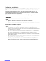
Safeguards
Please read through this Installation Guide carefully before installing the Axis product. Keep the
Installation Guide for further reference.
• Store the Axis product in a dry and ventilated environment.
• Avoid exposing the Axis product to vibration, shocks or heavy pressure. Do not install the
product on unstable brackets, unstable or vibrating surfaces or walls, since this could cause
damage to the product.
• Only use applicable tools when installing the Axis product; excessive force could cause
damage to the product.
• Do not use chemicals, caustic agents, or aerosol cleaners. Use a damp cloth for cleaning.
• Use only accessories that comply with technical specification of the product. These can be
provided by Axis or a third party.
• Use only spare parts provided by or recommended by Axis.
• Do not attempt to repair the product by yourself, contact Axis or your Axis reseller for ser-
vice matters.
• This Axis product shall be used in compliance with local laws and regulations.
• The Axis product should be installed by a trained professional. Observe relevant national
and local regulations for the installation.
Transportation
• When transporting the Axis product, use the original packaging or equivalent to prevent
damage to the product.

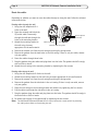
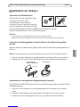
Battery Replacement
This Axis product uses a 3.0 V CR2032 lithium battery as the power supply for its internal real-time
clock (RTC). Under normal conditions this battery will last for a minimum of 5 years. Low battery
power affects the operation of the RTC, causing it to reset at every power-up. A log message will
appear when the battery needs replacing. The battery should not be replaced unless required!
If the battery does need replacing, please contact www.axis.com/techsup for assistance.
• Dispose of used batteries according to the manufacturer's instructions.
• Risk of explosion if battery is incorrectly replaced.
• Replace only with the same or equivalent battery, as recommended by the manufacturer.
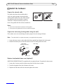
Dome Cover Cleaning
• Be careful not to scratch or damage the dome cover. Keep the protective plastic on the
dome cover until the installation is complete. Do not clean a dome cover that looks clean to
the eye and never polish the surface. Excessive cleaning could damage the surface.
• For general cleaning of a dome cover it is recommended to use a non-abrasive, solvent-free
neutral soap or detergent with water and a soft cloth. Rinse well with clean lukewarm
water. Dry with a soft cloth to prevent water spotting.
• Never use harsh detergents, gasoline, benzene or acetone etc. and avoid cleaning in direct
sunlight or at elevated temperatures.
• Domes for L products come with an anti-scratch surface. Avoid leaving finger prints on the
dome surface since this might impair image quality.

AXIS P33-VE Network Cameras Installation Guide Page 5
ENGLISH
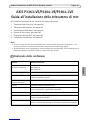
AXIS P3363-VE/P3364-VE/P3364-LVE
Network Camera Installation Guide
Follow these instructions to install the network camera
1. “Package contents” on page 5
2. “Hardware overview” on page 6
3. “Install the hardware” on page 7
4. “Access the video stream” on page 10
5. “Adjust the Lens” on page 10
6. “Complete the installation” on page 11
Notes:
• Before you begin, make sure that the package contents, power supply, and the required cables, tools, and
documentation are available. See Package contents below.
• This network camera is intended to operate with PoE; if not available use Axis PoE Midspan 1 port (not
included)
Package contents
Item Models/variants/notes
Network camera
with heating module
AXIS P3363-VE
AXIS P3364-VE
AXIS P3364-LVE
Mounting bracket
Dome covers Clear transparent cover (not for AXIS P3364-LVE)
Smoked transparent cover
Weather shield Not applicable for AXIS P3364-LVE
Labels 2 adhesive serial no. labels
Mounting kit Resitorx screw driver, 2 long screws, drill template, 5-meter network cable
with gasket, 1 gasket, terminal block connector
CD Installation and Management Software CD
Printed Materials Installation Guide (this document)
AVHS Authentication key
Optional accessories Threaded adaptor with cable shield
See www.axis.com for information on available accessories

Page 6 AXIS P33-VE Network Cameras Installation Guide
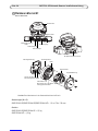
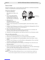
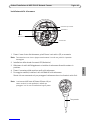
Hardware overview
Dimension (HxW)
AXIS P3363-VE/AXIS P3364-VE/AXIS P3364-LVE = 110 x 179 x 179 mm (4.33 x 7.05 x 7.05")
Weight
AXIS P3363-VE/AXIS P3364-VE = 1.5 kg (3.2 lb.)
AXIS P3364-LVE = 1.5 kg (3.3 lb.)
Unit casing
Camera unit
Dome cover
Side holes with
LED indicators
Control button
Camera AXIS P3364-L
Audio in
Audio out
SD memory card slot
Serial no.
Heater
Spring
routed along the wall
for cablesgaskets
I/O connector
Mounting bracket
Caution! The heater in the camera unit may be hot.
Network connector
(PoE)
Holes for cables
routed through the wall

AXIS P33-VE Network Cameras Installation Guide Page 7
ENGLISH
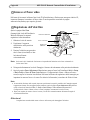
Install the hardware
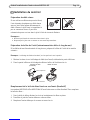
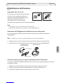
Prepare the network cable
If a cable other than the provided cable is
used, you need to prepare a network cable
with a gasket. Gently force the cable through
the gasket provided and attach a network
connector. It may be necessary to pierce a
hole in the gasket with the resitorx screwdriver.
Notes:
• Do not force the network connector into the gasket.
• Do not pierce the gasket with a knife or other sharp object.
Prepare the unit casing (routing cables along the wall)
If the cables are to be routed along the wall, prepare the unit casing as follows:
Note: The cable shield is an optional accessory, not supplied with the product.
1. Loosen the two screws on the cable shield (not supplied) and detach the bottom part.
2. Attach the bottom part of the cable shield to the unit casing with the screw.
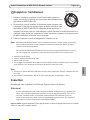
Replace clear/smoked dome cover (optional)
AXIS P3363-VE/AXIS P3364-VE is supplied with an optional dome. To replace the dome cover:
1. Loosen the 4 screws under the dome cover that hold the dome in place.
2. Transfer the gasket from the old dome to the new.
3. Replace the old dome with the new and tighten the screws.
Top part
Bottom part
Cable shield Unit casing
(optional accessory)

Page 8 AXIS P33-VE Network Cameras Installation Guide
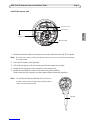
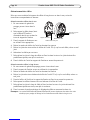
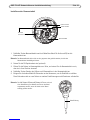
Route the cables
Depending on whether you want to route the cables through or along the wall, follow the relevant
instructions below.
Routing cables through the wall
1. Using the drill template drill 4
holes in the wall.
2. Route the network cable (and the
I/O, audio cable if necessary)
through the wall and through the
holes in the mounting bracket.
3. Attach the mounting bracket to
the wall using 4 screws
appropriate for the wall material.
4. Remove the camera unit from the unit casing by pushing the springs aside.
5. Remove the gaskets from the back holes in the unit casing. If there is only one cable, remove
only one gasket.
6. Route the cables through these holes.
7. Drag the gaskets along the cables and plug them into the holes. The gaskets should fit snugly
with no folds or bends.
8. Attach the unit casing to the mounting bracket by tightening the four screws.
Routing cables along the wall
1. Using the drill template drill 4 holes in the wall.
2. Attach the mounting bracket to the wall using 4 screws appropriate for the wall material.
3. Remove the camera unit from the unit casing by pushing the springs aside.
4. Remove the gaskets from the side holes in the unit casing. If there is only one cable, remove
only one gasket.
5. Place the unit casing on the mounting bracket and attach it by tightening the four screws.
6. Pull the cables up through the side holes in the unit casing.
7. Drag the gaskets along the cable and plug them into the holes. The gaskets should fit snugly in
the holes with no folds or bends.
8. Re-attach the top part of the cable shield by tightening the two screws.
Note: The AXIS P3363-VE/P3364-VE/P3364-LVE can also be fitted with a metal conduit for protecting
the cabling when cables are routed along the wall.
Mounting bracket
Network cable with gasket
Unit casing
Remove gaskets
from holes

AXIS P33-VE Network Cameras Installation Guide Page 9
ENGLISH
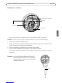
Install the camera unit
1. Attach the network cable to the camera unit; and the cable for audio and I/O if required.
Note: Be careful not to stretch or bend the network cable too much since this could cause damage to
the network cable.
2. Insert the SD memory card (optional).
3. Pull aside the springs in the unit casing and click the camera unit in place.
4. Attach the fan connector to the connector in the camera unit.
5. Attach the two M4x8 20 screws to the camera for greater stability.
These screws are only necessary to secure against heavy shocks and vibrations.
Note: The AXIS P3363-VE/P3364-VE/P3364-LVE can also be fit-
ted with a metal conduit for protecting the cabling when
cables are routed along the wall.
Connector for fan
Camera unit
Network cable
Attach
screw to camera
Conduit

Page 10 AXIS P33-VE Network Cameras Installation Guide
Access the video stream
Use the tools provided on the Installation and Management Software CD to assign an IP address,
set the password and access the video stream. This information is also available from the support
pages on www.axis.com/techsup
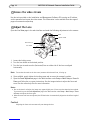
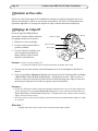
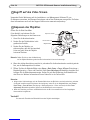
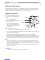
Adjust the Lens
Open the Live View page in the web interface and make the following adjustments to the camera:
1. Loosen the locking screw.
2. Turn the lens holder to the desired position.
3. Turn the lens to make sure the (horizontal) lines on either side of the lens are aligned
horizontally.
Note: Ensure that the mark on the lens cover, between the horizontal lines, is facing up.
4. Once satisfied, gently tighten the locking screw and to secure the camera’s position.
5. Open the Focus Adjustment page in the Web interface under Setup > Basic Setup > Focus &
Zoom, and follow the on-screen instructions. Use the image window to adjust the focus and
zoom. See the online help files for more information.
Notes:
• Due to the dome’s refraction, the image may appear slightly out of focus once the dome has been placed.
To correct this go to the Focus Adjustment page in the Web interface under Setup > Basic Setup > Focus
& Zoom, and adjust the focus again.
• When the zoom and focus are adjusted, the IR illumination is automatically aligned to the defined angle of
view.
Caution!
Adjusting the focus and zoom manually can damage the lens.
Locking screw
Horizontal line
Mark
Lens holder
Optical shield

AXIS P33-VE Network Cameras Installation Guide Page 11
ENGLISH
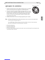
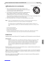
Complete the installation
1. Rotate the black protective shield inside the dome cover so it is aligned
with the camera’s position (not applicable to AXIS P3364-LVE).
2. If required, attach the weather shield to the camera before you attach
the dome cover (not applicable to AXIS P3364-LVE). To do this remove
the two screws in the dome cover. Transfer the washers from these
screws to the two long screws provided. Attach the weather shield
using the two long screws.
3. Attach the dome cover to the unit casing by tightening the 4 screws.
Note: AXIS P3364-LVE Network Camera: Before attaching the dome cover make sure the optical shield
sits well in place. See image on page 10.
For the AXIS P3364-LVE Network Camera, when the lens holder is tilted at a certain angle the
dome cover may block part of the IR illumination. In that case:
• loosen the locking screw
• rotate the lens holder 180°
• tighten the locking screw
• for correct image orientation, rotate the lens by 180°; make sure the horizontal lines are aligned and the
mark between them is facing up.
Black protective shield

Page 12 AXIS P33-VE Network Cameras Installation Guide
Unit connectors
Network connector - RJ-45 Ethernet connector. Supports Power over Ethernet.
The product shall be connected using a shielded network cable (STP). All cables connecting the
product to the network switch shall be shielded (STP) and intended for their specific use. Make
sure that the network switch is properly grounded. See Electromagnetic Compatibility (EMC) on
page 2 for regulatory requirements.
Audio in - 3.5mm input for a mono microphone, or a line-in mono signal (left channel is used from
a stereo signal).
Audio out - Audio output (line level) that can be connected to a public address (PA) system or an
active speaker with a built-in amplifier. A pair of headphones can also be attached. A stereo
connector must be used for the audio out.
SDHC memory card slot - The SD memory card can be used for local recording with removable
storage.
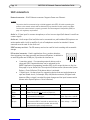
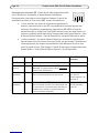
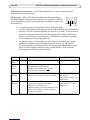
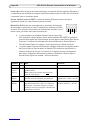
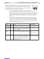
I/O terminal connector - Used in applications for e.g. motion detection,
event triggering, time lapse recording and alarm notifications. In addition to
an auxiliary power and a GND pin, it provides the interface to:
• 1 transistor output - For connecting external devices such as
relays and LEDs. Connected devices can be activated by the
VAPIX® Application Programming Interface (API), by the output buttons on the Live
View page or by an Action Rule. The output will show as active (shown under System
Options > Ports & Devices) if the alarm device is activated.
• 1 digital input - An alarm input for connecting devices that can toggle between an
open and closed circuit, for example: PIRs, door/window contacts, and glass break
detectors. When a signal is received the state changes and the input becomes active
(shown under System Options > Ports & Devices).
Function Pin Notes Specifications
GND 1 Ground
3.3V DC
Power
2 Can be used to power auxiliary equipment.
Note: This pin can only be used as power out.
Max. load = 50mA
Digital
Input
3 Connect to GND to activate, or leave floating (or
unconnected) to deactivate.
Min. input= 0 to - 40V DC
Max. input=0 to + 40V DC
Digital
Output
4 Uses an open-drain NFET transistor with the source
connected to GND. If used with an external relay, a
diode must be connected in parallel with the load,
for protection against voltage transients.
Max. load = 100mA
Max voltage = + 40V DC
Pin1
Pin2
Pin3
Pin4

AXIS P33-VE Network Cameras Installation Guide Page 13
ENGLISH
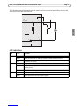
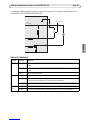
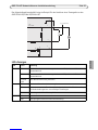
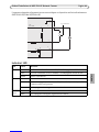
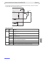
The following connection diagram gives an example of how to connect an auxiliary device to the
AXIS P3363-VE/P3364-VE/P3364-LVE.
LED indicators
LED Color Indication
Network Green Steady for connection to a 100 Mbit/s network. Flashes for network activity.
Amber Steady for connection to 10 Mbit/s network. Flashes for network activity.
Unlit No network connection.
Status Green Steady green for normal operation.
Amber Steady during startup; flashes once during reset to factory default or while
restoring settings.
Red Slow flash for failed upgrade.
Power Green Normal operation.
Amber Flashes green/amber during firmware upgrade.
1
2
E.g. push button
3
4
3.3V
max. 50mA
D
S
G

Page 14 AXIS P33-VE Network Cameras Installation Guide
Resetting to the Factory Default Settings
This will reset all parameters, including the IP address, to the factory default settings:
1. Disconnect power from the camera.
2. Press and hold the Control button and reconnect power (see “Hardware overview” on page 6).
3. Keep the Control button pressed for about 15 seconds until the Status indicator displays amber.
4. Release the Control button. The process is complete after about 1 minute (when the Status
indicator turns green). The network camera has been reset to the factory default settings. The
default IP address is 192.168.0.90
5. Re-assign the IP address.
6. Refocus the camera.
It is also possible to reset parameters to factory default via the web interface. Go to Setup > System
Options > Maintenance.
Further information
The user manual is available from the Axis Web site at www.axis.com. To learn more about Axis'
products and technologies, visit www.axis.com/academy, the global learning center for network
video.
Tip!
Visit www.axis.com/techsup to check if there is updated firmware available for your Axis product.
To see the currently installed firmware version, see Setup > About in your web interface.
Warranty
For information about Axis' product warranty and thereto related information, please see
www.axis.com/warranty

FRANÇAIS
Mesures de sécurité
Lisez attentivement le présent Guide d'installation avant d'installer le produit Axis. Conservez le
Guide d'installation pour une utilisation ultérieure.
• Conservez le produit Axis dans un environnement sec et aéré.
• Évitez d'exposer le produit Axis aux vibrations, aux chocs ou à une forte pression.
N'installez pas le produit sur un support instable, ou des surfaces ou des murs instables ou
vibrants, car cela pourrait l'endommager.
• N'utilisez que les outils applicables pour installer le produit Axis ; une force excessive
pourrait endommager le produit.
• Pour le nettoyage, n’utilisez ni produits chimiques, ni substances caustiques ou aérosols.
Utilisez un chiffon humide pour le nettoyage.
• N’utilisez que des accessoires conformes aux caractéristiques techniques du produit. Ceux-
ci peuvent être fournis par Axis ou par un fournisseur tiers.
• Utilisez uniquement des pièces de rechange fournies ou recommandées par Axis.
• Ne tentez pas de réparer le produit vous-même, contactez Axis ou votre revendeur Axis
pour toute réparation.
• Ce produit Axis doit être utilisé conformément aux lois et réglementations locales en
vigueur.
• Pour pouvoir être utilisé à l'extérieur, ce produit Axis doit être placé dans un boîtier
d'extérieur homologué.
• Le produit Axis doit être installé par un professionnel qualifié. Veuillez vous conformer aux
règlements nationaux et locaux relatifs à l'installation.
Transport
• Pour transporter le produit Axis et éviter de l'endommager, utilisez l'emballage d'origine ou
un emballage équivalent.

Remplacement des piles
Ce produit Axis nécessite une pile au lithium CR2032 de 3,0 V pour l'alimentation de son horloge en
temps réel interne. Dans des conditions normales d'utilisation, cette pile est censée durer au moins
5 ans. Si la pile est faible, le fonctionnement de l'horloge en temps réel peut être affecté et
entraîner sa réinitialisation à chaque mise sous tension. Un message enregistré apparaît lorsque la
pile doit être remplacée. Ne remplacez la pile qu'en cas de nécessité !
Si la pile doit être remplacée, veuillez contacter www.axis.com/techsup pour obtenir de l’aide.
• Jetez les piles usagées conformément aux consignes du fabricant.
• Le remplacement incorrect de la pile peut entraîner un risque d'explosion.
• Remplacez la pile par une pile identique ou équivalente uniquement, en respectant les
recommandations du fabricant.
Nettoyer la bulle du dôme
• Veillez à ne pas rayer ou endommager la bulle du dôme. Ne nettoyez pas la bulle du dôme si
elle semble propre à l'œil nu et ne frottez jamais sa surface. Un nettoyage excessif peut
l'endommager.
• Pour le nettoyage général de la bulle du dôme, il est recommandé d'utiliser un savon ou un
détergent neutre sans solvant, non abrasif, avec de l'eau et un chiffon doux. Rincez
abondamment avec de l’eau tiède et propre. Séchez à l'aide d'un chiffon doux pour éviter
les tâches d'eau.
• N'utilisez jamais de détergents forts, d'essence, de benzène ou d'acétone, etc. et évitez
toute exposition directe aux rayons du soleil ou à des températures élevées lors du
nettoyage.
• Les bulles pour les produits L sont livrées avec une surface anti-rayures et le nettoyage de
la bulle est recommandé, cependant veuillez respecter les précautions ci-dessus.

Guide d’installation des Caméra réseau AXIS P33-VE Page 17
FRANÇAIS
AXIS P3363-VE/P3364-VE/P3364-LVE
Guide d’installation de la caméra réseau
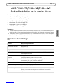
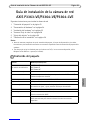
Procédez comme suit pour installer la caméra réseau.
1. « Contenu de l’emballage » à la page 17
2. « Présentation du matériel » à la page 18
3. « Installation du matériel » à la page 19
4. « Accéder au flux vidéo » à la page 22
5. « Réglage de l’objectif » à la page 22
6. « Fin de l’installation » à la page 23
Remarques :
• Avant de commencer, vérifiez le contenu de l’emballage et assurez-vous que l’alimentation ainsi que les
câbles, les outils et la documentation nécessaires sont disponibles. Voir Contenu de l’emballage ci-dessous.
• Cette caméra réseau est conçue pour fonctionner avec un connecteur réseau (PoE). Si vous n’en disposez
pas, utilisez l’injecteur PoE Axis à 1 port (non fourni).
Contenu de l’emballage
Élément Modèles/variantes/remarques
Caméra réseau
avec module chauffant
AXIS P3363-VE
AXIS P3364-VE
AXIS P3364-LVE
Support de fixation
Bulles de dôme Bulle transparente non fumée (non applicable pour l’AXIS P3364-LVE)
Bulle transparente fumée
Protection étanche Non applicable pour l’AXIS P3364-LVE
Étiquettes 2 étiquettes adhésives portant le numéro de série
Kit de montage Tournevis Resitorx, 2 vis longues, gabarit de perçage, câble réseau de
5 mètres avec joint, 1 joint, connecteur de bornier.
CD CD du logiciel d'installation et de gestion
Documentation imprimée Guide d’installation (le présent document)
Clé d’authentification AVHS
Accessoires en option Adaptateur filet avec câble blindé
Rendez-vous sur www.axis.com pour en savoir plus sur les accessoires
disponibles.

Page 18 Caméra réseau AXIS P33-VE Guide d’installation
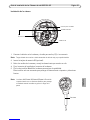
Présentation du matériel
Dimensions (H x l)
AXIS P3363-VE, AXIS P3364-VE, AXIS P3364-LVE = 110 x 179 x 179 mm (4,33 x 7,05 x 7,05")
Poids
AXIS P3363-VE, AXIS P3364-VE = 1,5 kg
AXIS P3364-LVE = 1,5 kg
Boîtier de l’unité
Caméra
Couvercle du dôme
Trous latéraux avec
Voyants lumineux
Bouton de commande
Caméra AXIS P3363
Entrée audio
Sortie audio
Logement pour carte mémoire SD
Numéro de série
Élément chauffant
Ressort
acheminés le long du mur
pour les câblesjoints
Connecteur d’E/S
Support de fixation
Attention : l’élément thermique de la caméra peut être chaud.
Connecteur réseau
(PoE)
Trous pour les câbles
acheminés dans le mur

Guide d’installation des Caméra réseau AXIS P33-VE Page 19
FRANÇAIS
Installation du matériel
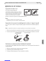
Préparation du câble réseau
Si vous utilisez un câble autre que celui fourni,
il est nécessaire de préparer un câble réseau
avec un joint. Faites passer délicatement le
câble à travers le joint fourni et complétez-le
par un connecteur réseau. Il peut être
nécessaire de percer un trou dans le joint à l’aide du tournevis Resitorx.
Remarques :
• Ne forcez pas l’entrée du connecteur réseau dans le joint.
• Ne percez pas le joint avec un couteau ou tout autre objet tranchant.
Préparation du boîtier de l’unité (acheminement des câbles le long du mur)
Si les câbles doivent être acheminés le long du mur, préparez le boîtier de l’unité de la manière
suivante :
Remarque : Le blindage de câble est facultatif, et n’est pas fourni avec le produit.
1. Dévissez les deux vis sur le blindage de câble (non fourni) et détachez la partie inférieure.
2. Fixez la partie inférieure du blindage de câble au boîtier de l’unité avec la vis.
Remplacement de la bulle de dôme fumée ou non fumée (facultatif)
Les caméras AXIS P3363-VE et AXIS P3364-VE sont livrées avec un dôme facultatif. Pour remplacer
la bulle du dôme :
1. Sous la bulle du dôme, dévissez les 4 vis qui maintiennent le dôme en place.
2. Transférez le joint de l’ancien dôme au nouveau dôme.
3. Remplacez l’ancien dôme par le nouveau et serrez les vis.
Partie supérieure
Partie inférieure
Blindage de câble Boîtier de l’unité
(facultatif)

Page 20 Caméra réseau AXIS P33-VE Guide d’installation
Acheminement des câbles
Selon que vous souhaitez faire passer les câbles le long du mur ou dans le mur, suivez les
instructions correspondantes ci-dessous.
Acheminement des câbles dans le mur
1. En vous servant du gabarit de
perçage, percez 4 trous dans le
mur.
2. Faites passer le câble réseau (ainsi
que le câble d’E/S audio si
nécessaire) dans le mur et dans les
trous du support de fixation.
3. Fixez le support de fixation au mur
en utilisant 4 vis appropriées.
4. Retirez la caméra du boîtier de l’unité en écartant les ressorts.
5. Retirez les joints des trous arrière du boîtier de l’unité. S’il n’y a qu’un seul câble, retirez un seul
joint.
6. Acheminez les câbles par ces trous.
7. Faites glisser les joints le long des câbles et fixez-les dans les trous. Les joints doivent être
parfaitement ajustés, sans plis ni courbures.
8. Fixez le boîtier de l’unité au support de fixation en serrant les quatre vis.
Acheminement des câbles le long du mur
1. En vous servant du gabarit de perçage, percez 4 trous dans le mur.
2. Fixez le support de fixation au mur en utilisant 4 vis appropriées.
3. Retirez la caméra du boîtier de l’unité en écartant les ressorts.
4. Retirez les joints des trous latéraux du boîtier de l’unité. S’il n’y a qu’un seul câble, retirez un
seul joint.
5. Posez le boîtier de l’unité sur le support de fixation et fixez-le en serrant les quatre vis.
6. Faites passer les câbles à travers les trous latéraux du boîtier de l’unité.
7. Faites glisser les joints le long du câble et fixez-les dans les trous. Les joints doivent être
parfaitement ajustés aux trous, sans plis ni courbures.
8. Fixez à nouveau la partie supérieure du blindage de câble en resserrant les deux vis.
Remarque : Les caméras AXIS P3363-VE/P3364-VE/P3364-LVE peuvent également être dotées d’un tube
métallique pour protéger le câblage lors de l’acheminement des câbles le long du mur.
Support de fixation
Câble réseau avec joint
Boîtier de l’unité
Retirez les joints
des trous
Seite wird geladen ...
Seite wird geladen ...
Seite wird geladen ...
Seite wird geladen ...
Seite wird geladen ...
Seite wird geladen ...
Seite wird geladen ...
Seite wird geladen ...
Seite wird geladen ...
Seite wird geladen ...
Seite wird geladen ...
Seite wird geladen ...
Seite wird geladen ...
Seite wird geladen ...
Seite wird geladen ...
Seite wird geladen ...
Seite wird geladen ...
Seite wird geladen ...
Seite wird geladen ...
Seite wird geladen ...
Seite wird geladen ...
Seite wird geladen ...
Seite wird geladen ...
Seite wird geladen ...
Seite wird geladen ...
Seite wird geladen ...
Seite wird geladen ...
Seite wird geladen ...
Seite wird geladen ...
Seite wird geladen ...
Seite wird geladen ...
Seite wird geladen ...
Seite wird geladen ...
Seite wird geladen ...
Seite wird geladen ...
Seite wird geladen ...
Seite wird geladen ...
Seite wird geladen ...
Seite wird geladen ...
Seite wird geladen ...
Seite wird geladen ...
Seite wird geladen ...
Seite wird geladen ...
Seite wird geladen ...
-
 1
1
-
 2
2
-
 3
3
-
 4
4
-
 5
5
-
 6
6
-
 7
7
-
 8
8
-
 9
9
-
 10
10
-
 11
11
-
 12
12
-
 13
13
-
 14
14
-
 15
15
-
 16
16
-
 17
17
-
 18
18
-
 19
19
-
 20
20
-
 21
21
-
 22
22
-
 23
23
-
 24
24
-
 25
25
-
 26
26
-
 27
27
-
 28
28
-
 29
29
-
 30
30
-
 31
31
-
 32
32
-
 33
33
-
 34
34
-
 35
35
-
 36
36
-
 37
37
-
 38
38
-
 39
39
-
 40
40
-
 41
41
-
 42
42
-
 43
43
-
 44
44
-
 45
45
-
 46
46
-
 47
47
-
 48
48
-
 49
49
-
 50
50
-
 51
51
-
 52
52
-
 53
53
-
 54
54
-
 55
55
-
 56
56
-
 57
57
-
 58
58
-
 59
59
-
 60
60
-
 61
61
-
 62
62
-
 63
63
-
 64
64


Axis Communications P3363-VE Benutzerhandbuch
- Typ
- Benutzerhandbuch
in anderen Sprachen
Verwandte Artikel
Andere Dokumente
-
Axis P3363-VE Installationsanleitung
-
Axis P3353-V Installationsanleitung
-
Axis P3364-LV Installationsanleitung
-
-
Axis P3364-V Installationsanleitung
-
-
Axis Q1921 Installationsanleitung
-
-
Axis P3346-VE Installationsanleitung
-
Axis Q3505-V Benutzerhandbuch