
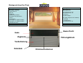
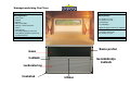
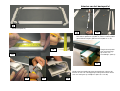
Basis Profil
Zugleiste
Gaze
Verdunkelung
Eckstück
Klickmechanismus
Führungsblock
Benötigtes Zubehör:
- Stanley-Messer
- Bleistift
- Bandmaß
- Spundschlüssel M2,5
- Kreuzkopfschraubendreher
- Schere
- Schleifpapier
- Eisensäge (als Option lieferbar)
- Gehrladen (als Option lieferbar)
- Akkubohrmaschine
www.horrex.nl
Montagebeutel:
- 8x Schraube 3,5 x 6,5
- 4x Schraube 3,0 x 30
- 2x Klemme
- 4x Abdeckkappe
(Als Option mitgeliefert ab 1300mm)
- 1x Z-Profil
- 1x Metallklemme
- 2x Schraube 3,5 x 25
www.horrex.nl
Montageanleitung Duo Plissé

1
2
3
4
5
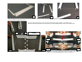
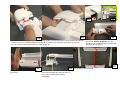
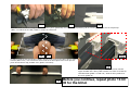
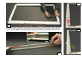
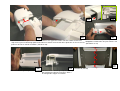
Nach dem Entfernen der Verpackung legen Sie das Duo Plissé auf einen flachen Untergrund, wie angegeben auf Foto 1, 2 und 3. (Achten Sie darauf,
dass die Schnüre nicht gekreuzt sind).
Lösen Sie die Schnurspanner an den Seiten mit einem Inbusschlüssel M2,5, siehe Foto 4 und 5.
Schieben Sie die Schnurspanner aus den Seiten. (Eine Gesamtdarstellung sehen Sie auf Foto 6 und 7.)
6 7
Schnitt
10
11
8
9
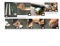
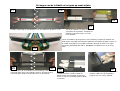
Entfernen Sie vorsichtig die Eckstücke an den vier Seiten, siehe Foto
8,9,10 und 11; die Gesamtdarstellung sehen Sie auf Foto 12.
6
7

12
Kürzen des Basisprofils
13
14
15
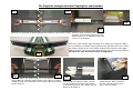
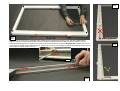
Schieben Sie das Basisprofil vom Gazepaket ab, siehe
Foto 13. Das Basisprofil liegt jetzt lose (Foto 14) und Sie können
das Basisprofil in der gewünschten Länge abzeichnen (Foto 15 -16).
16
17
Sägen Sie das
Basisprofil mit einer
Eisensäge im
Gehrladen auf die
richtige Länge (Foto
17).
18 19 20
Nachdem Sie das Basisprofil auf die richtige Länge gesägt
haben, schleifen Sie die Grate mit einem Schleifpapier glatt;
grobe Grate können Sie mit einem Stanley-Messer entfernen
(Foto 18, 19 und 20).
Gesamtdarstellung (Foto 12)

Die Zugleiste zusägen und das Fliegengitter zuschneiden
21
22
23
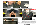
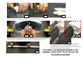
Entfernen Sie vorsichtig die Führungsblöcke der Zugleiste, siehe Foto 21 und 22.
Schieben Sie die Zugleiste vom Gazepaket
herunter, siehe Foto 23. Entfernen Sie den
Klickmechanismus und die Bürste links und
rechts aus der Zugleiste.
24
Zeichnen Sie die richtige Länge der Zugleiste ab (Foto 24). Beachten Sie dabei,
dass die Zugleiste auf beiden Seiten gleichermaßen gekürzt werden muss, damit
die Schnüre, die durch das Gaze und das Verdunkelung verlaufen, in der Mitte
bleiben (Foto 25). Die gesamte abzusägende Länge muss durch 2 geteilt werden.
(Beachten Sie, dass die Schnur nicht in die Säge gerät).
25
26
27
28
Nach dem Kürzen der Zugleiste können Sie den Klickmechanismus
und die Bürsten auf beiden Seiten wieder in die Zugleiste schieben;
die Bürste können Sie auf beiden Seiten auf dieselbe Länge kürzen
wie die Zugleiste.
Jetzt können Sie die Führungsblöcke wieder
auf der Zugleiste montieren. Dazu stecken
Sie den schwarzen Streifen mit der Schnur
in die oberste Kammer und schieben Sie den
Block auf die Zugleiste.
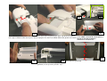
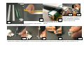
Jetzt muss das Fliegengitter noch
gekürzt werden. Dazu schneiden
Sie zuerst den Streifen mit einer
Schere durch (Foto 29).
29

32
33
34
34a
30a
30b
31
35
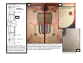
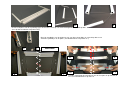
Jetzt können Sie die Gaze mit einem Stanley-Messer gerade nach unten durchschneiden (Foto 30a) und den unteren schwarzen Streifen wieder mit einer
Schere durchschneiden (Foto 30b). Das Endergebnis sehen Sie auf Foto 31. (Achten Sie darauf, dass Sie die Schnur nicht durchschneiden).
Die äußere Falte des Gazepakets muss auf beiden Seiten eingeschnitten werden, damit Sie
die Gazepaket wieder in das Basisprofil und später in das Eckstück schieben können.
Bringen sie einen Schnitt mit einer Länge von ungefähr 2 cm in der ersten Falte hinter dem
schwarzen Streifen an (Foto 32 und 33)
Zugleiste
Schieben Sie den schwarzen Streifen, in dem Sie gerade den
Schnitt angebracht haben, in die obere Kammer des Basisprofils.
Der Rest des Gazepakets kommt in die darunter liegende Kammer
(Foto 34 und 34a). Schieben Sie das Basisprofil über die Gazepaket
(Foto 35).
Bevor Sie weitermachen, wiederholen Sie die
Schritte ab Foto 13 bis Foto 35 für das
Verdunkelung

36
37
38
39
40
41 42 43 44
Sie können jetzt das Basisprofil der Seiten des Duo Plissé abzeichnen und
auf die gewünschte Länge kürzen (Foto 36 und 37).
Sägen Sie das Basisprofil mit einer
Eisensäge im Gehrladen auf die
richtige Länge (Foto 38).
Nachdem Sie die Basisprofile auf die
richtige Länge gesägt haben, schleifen
Sie die Grate mit einem Schleifpapier
glatt; grobe Grate können Sie mit einem
Stanley-Messer entfernen (Foto 39 und
40).
Auf den Fotos 41 bis 44 ist dargestellt, wie die Schnur gekürzt werden kann, wenn diese zu lang zum Spannen sein sollte. Dies kann der Fall sein, wenn Sie die
Seiten so stark gekürzt haben, dass die Spannblöcke gegeneinander kommen und nicht mehr unter Spannung zu setzen sind. Wenn dies der Fall ist,
laufen Sie die Schritte durch auf Foto 41 bis 44.

45
46
47
46a
46b
48
49
50
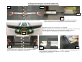
Nach dem Kürzen der Seiten können die Eckstücke wieder angebracht werden. Führen Sie dazu den oberen
Streifen des Gaze-/ Verdunkelungspakets in die obere Kammer des Eckstücks ein und lassen Sie den
Rest des Pakets in der unteren Kammer (Foto 45 und 46).
Schieben Sie das Eckstück dann auf das
Basisprofil. Achten Sie darauf, dass das
Eckstück in die richtigen Kammern eingesetzt
wird (Foto 46a+b und 47).
Schieben Sie das Eckstück dann auf das
Basisprofil.
Gesamtdarstellung (Foto 50)
Kontrollieren Sie, dass die Schnüre gut laufen,
siehe Foto 49. Wenn dies nicht der Fall ist,
müssen Sie die vorherigen Schritte
wiederholen.

51b
51
51a
52 53
54
55
56
57
Bringen Sie die Schnurspanner in beiden Seiten an L+R (Foto 51+a+b).
Stecken Sie die Seite in das Eckstück (Foto 52). Achten Sie darauf, dass die Schnüre nicht
im Eckstück eingeklemmt werden (Foto 53). Sorgen Sie dafür, dass die Eckstücke gut
anschließen (Foto 54).
Nachdem die Eckstücke angebracht sind, können Sie den Duo Plissé umdrehen, um die Eckstücke auf der Rückseite festzuschrauben. Drücken Sie die
Basisprofile gut gegen das Eckstück, sodass keine Nähte zwischen dem Basisprofil und dem Eckstück entstehen. Schrauben Sie die Schraube 3,5x6,5 mit
einer Akkubohrmaschine in das Eckstück, siehe Foto 55 bis 57.

Klemme
richtig
Zu stark gespannt
58
59
60
61
59a
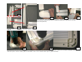
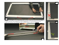
Das Spannen des Duo Plissé erfolgt durch das Anbringen der mitgelieferten Klemmen auf dem Basisprofil und der
Zugleiste. Mit einem Spundschlüssel M2,5 können Sie den Schnurspanner lösen und nach vorne schieben, um das
Gaze/Verdunkelungspaket zu spannen. Sie müssen alle 4 Schnurspanner spannen. Beachten Sie Foto 60: wenn Sie zu
stark spannen, ziehen Sie die Zugleiste schief. Auf Foto 61 sehen Sie eine richtige gespannte Ausführung. Drehen Sie die
Schnurspanner handfest an! Fest ist fest.

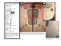
Durchsnitt
Seite der Wand
Z-Profil
Metallklemme
Gummi
Rubber
Wand
wand
62
63a
63
64
Bei einer Abmessung ab 1300mm
werden ein Z-Profil und eine Klemmfeder
aus Metall mitgeliefert. Damit wird dem
Durchbiegen des Basisprofils vorgebeugt.
Diese können Sie in der Mitte über und
unter dem Fenstergummi befestigen
(OPTION ab
1300 mm Breite)
Bringen Sie die Abdeckkappen auf
den Eckstücken an (Foto 64).
Das Duo Plissé-Rollo kann jetzt montiert werden. Halten Sie das
Duo Plissé-Rollo dazu vor das Fenster und schrauben Sie es mit der
Schraube 3,0x30 an der richtigen Stelle fest. Zum Festschrauben verwenden
Sie einen Kreuzschraubendreher. Schrauben Sie zuerst die Oberseite fest
und dann die Unterseite. Achten Sie beim Festschrauben darauf, dass
die Schnur nicht mit festgeschraubt wird (Foto 63a).
Achten Sie beim Befestigen
auf die Schnur!

Base profile
Pull bar
Mesh
Blind
Corner piece
Clicker
Guidance block
Pull bar
Necessities:
- Stanley knife
- Pencil
- Measuring tape
- Allen Key (Hex key) M2,5
- Cross head screwdriver
- Scissors
- Sand paper
- metal saw (optional delivered)
- Mitre box (optional delivered)
- Battery drilling machine
www.horrex.nl
Assembly bag:
- 8x screw 3,5 x 6,5
- 4x screw 3,0 x 30
- 2x clamps
- 4x covers
(included from width 1300mm)
- 1x Z-profile
- 1x metal clamp
- 2x screw 3,5 x 25
www.horrex.nl
Manual adjustable Duo Plisse

1
2
3
4
5
After removal of the packaging, lay down the duo plisse on a flat surface (photo’s 1, 2 and 3). Make sure that the cords do not cross.
Turn loose the cord tensioners in the side profiles with an Allen key M2,5 (photo’s 4 and 5).
Push the cord tensioners out of the side profiles. (Photo’s 6 and 7 show the full picture)
6 7
Cut through
10
11
8
9
Remove the corner pieces from the four corners (photo’s 8,9,10 and 11).
6
7

12
Shortening of the base profile
13
14
15
Slide the mesh out of the base profile (photo 13). Now the base
profile is separated from the other parts (photo 14), the base
profile can be marked off (photo’s 15 and 16)
16
17
With the help of a
metal saw and mitre
box, cut the base
profile to the correct
size.
18 19 20
Remove possible burrs with a sand paper. To remove rough
burrs you can use a Stanley knife (photo’s 18, 19 and 20)
Photo 12 shows the overall picture.

Cutting and sawing of the mesh and pull bar
21
22
23
Carefully remove the guider blocks from the pull bar (photo’s 21 and 22).
Slide the mesh out of the pull bar a bit (photo 23). Remove the little black
clicker and the brushes left and right from the clicker from the pull bar.
24
Mark off the pull bar at the desired measure (photo 24).
Note that the pull bar needs to be shortened equally on both sides in order to keep
the cords that run through the mesh and blind in the middle (photo 25)
Therefore divide the total length that needs to be sawn of by 2.
25
26
27
28
Make sure to keep the cord away from the saw. After cutting the
pull bar the little clicker and brushes can be slided back into the
profile. Cut the brushes proportional to the pull bar.
The guider blocks can now be reconnected to
the pull bar; place the black strip in the
upper chamber of the guider block and attach
the guider block to the pull bar
Now the mesh must be cut to the right size.
To do this, first cut the strip with a pair of
scissors. (photo 29).
29

32
33
34
34a
30a
30b
31
35
Then the mesh can be cut straight down with a Stanley knife (photo 30a).Cut the bottom strip with the pair of scissors (photo 30b), like the strip on top.
(Make sure not to cut the cord.) Photo 31 shows the end result.
In order to slide the mesh in the base profile (and at a later stage in the corner piece) make an
incision (about 2 cm.) This incision has to be made in the outer pleat of the mesh (the first
pleat after the black strip) on both sides (photo’s 32 and 33).
Pull bar
Place the black strip, where you just made the incision, into the
upper chamber of the base profile and the rest of the mesh into the
chamber below (photo’s 34 and 34a ). Slide the base profile over
the mesh (photo 35).
Before you continue, repeat photo 13 till
35 for the blind.

36
37
38
39
40
41 42 43 44
Now you can mark off and subsequently shorten the base profile on both
sides of the Duo Plisse to the desired size (photo’s 36 and 37)
Use a metal saw and mitre box to saw
the base profile (photo 38).
Remove possible burrs with a sand
paper. To remove rough burrs you can
use a Stanley knife (photo’s 39 and 40).
Photo’s 41 till 44 show how to shorten the cord in case it’s too long for tensioning. This is necessary when the sides have been shortened to such a size
that the cord tensioners meet each other and because of this can not be tensioned to the right degree in such way.

45
46
47
46a
46b
48
49
50
After shortening the side profiles you can reinsert the corner pieces by placing the upper strip of the mesh/blind
in the upper chamber of the corner piece, while keeping the rest of the mesh/blind underneath (photo’s 45 and 46).
Now connect the corner piece to the base
profile. Make sure that the corner piece is
placed in the right chambers!
(Photo 46a+b and photo 47)
Push the corner piece to the base profile.
Check if the cords are in the right place
(photo 49). If not: repeat the previous steps.
Overall picture (photo 50).

51b
51
51a
52 53
54
55
56
57
Insert the cord tensioners in both side profiles (photo’s 51, 51a
and 51b).
Now connect the side profiles to the corner pieces (photo 52). Make sure the cords are not
jammed/stuck inside the corner pieces (photo 53) and that the corner pieces are well
connected (photo 54).
Turn around the Duo Plisse and screw down the corner pieces on the back side. Press the profiles against the corner pieces firml
y to avoid gaps between profiles
and corner pieces and use a battery drill to screw down screws 3,5 x 6,5 into the corner pieces (photo’s 55 to 57).

clamps
Right way
Too tight
58
59
60
61
59a
Tension the Duo Plisse by placing the clips on the base profile and pull bar. Use an Allen key M2,5 to loosen the cord
tensioner and push the cord tensioner forward in order to bring the mesh/blind to the correct tension. All 4 cord tensioners
need to be tensioned. Note: If the tension is too high the pull bar will be drawn out of it’s horizontal position (photo 60).
Photo 61 shows the correct way of tensioning. Fasten the cord tensioners by hand; fixed is fixed.

Cut through
Side view
Z-Profile
Metal clamp
Rubber
Rubber
wall
wall
62
Mind the cord
when fixing the
Duo Plissé!
63a
63
64
For Duo Plissees larger than 1300mm
a Z-profile and a metal clamp are included
to prevent the base profile from bending,
attach these right in the middle above and
under the window rubber
(OPTION from
width 1300mm)
At this point the Duo Plisse can be mounted on to the caravan window. Hold
the Duo Plissé in front of the window and fasten it with the screws size
3,0 x 30 and a crosshead screwdriver to the correct position, first at the top,
then at the bottom (photo 63). Make sure not to screw through the cord.
Place the covers over the
screw holes in the corner
pieces (photo 64).
Seite laden ...
Seite laden ...
Seite laden ...
Seite laden ...
Seite laden ...
Seite laden ...
Seite laden ...
Seite laden ...
Seite laden ...
Seite laden ...
-
 1
1
-
 2
2
-
 3
3
-
 4
4
-
 5
5
-
 6
6
-
 7
7
-
 8
8
-
 9
9
-
 10
10
-
 11
11
-
 12
12
-
 13
13
-
 14
14
-
 15
15
-
 16
16
-
 17
17
-
 18
18
-
 19
19
-
 20
20
-
 21
21
-
 22
22
-
 23
23
-
 24
24
-
 25
25
-
 26
26
-
 27
27
-
 28
28
-
 29
29
-
 30
30


in anderen Sprachen
- English: Horrex Duo Plisse User manual
- Nederlands: Horrex Duo Plisse Handleiding
Sonstige Unterlagen
-
GROHE SENSIA IGS Operating Instructions Manual
-
-
Parrot DF7220 Bedienungsanleitung
-
-
AudioSonic Tablet 9.7 Bedienungsanleitung
-
GYS DRAW ALIGNER Bedienungsanleitung
-
LG KP501.AORFSV Benutzerhandbuch
-
Husqvarna HO1997 Benutzerhandbuch
-
Epson Stylus Photo PX700W Bedienungsanleitung
-
LG KU990.AROMBK Benutzerhandbuch