

1 Lieferumfang
Darstellung Beschreibung
n OGM Commander Interface
n Netzteil
n Verbindungskabel
zwischen OGM
PLUS
und OGM Commander
n Verbindungskabel
zwischen OGM Commander und PC
(COM-Port)
n Bedienungsanleitung
(Art. Nr. 417101260)
Die jeweils aktuellste und komplette
Betriebsanleitung wird im Internet zur
Verfügung gestellt:
https://www.ecolab-engineering.de/fileadmin/
download/bedienungsanleitungen/mess-und-
regeltechnik/Ovalradz-hler-OGM-/
417101260_OGM_Commander_Interface.pdf
Lieferumfang
2Rev. 01-01.2020

2 Verwendungszweck und Installation
Das OGM Commander Interface dient der Konfiguration des
Ovalradzählers „OGM
PLUS
“ .
2.1 Voraussetzungen
PC mit:
n 1 freien seriellen (COM) Schnittstelle
oder
n USB-RS232 Konverter
oder
n PCMCIA-Steckkarte (bei Laptops)
2.2 Installation der OGM Commander-Software
Um die Konfiguration des OGM
PLUS
zu ermöglichen wird die
Software: „OGM Commander“ benötigt. Diese können Sie unter
folgendem Link:
https://www.ecolab-engineering.de/fileadmin/download/software/
OGM-Software/OGMCommander_1004.zip herunterladen.
Softwaredownload:
https://www.ecolab-engineering.de/fileadmin/
download/software/OGM-Software/
OGMCommander_1004.zip
Nach erfolgreichem Download der gepackten Datei muss diese auf
dem zu verwendenden PC entpackt und durch Ausführen der
„SETUP.EXE“ installiert werden.
Verwendungszweck und Installation
3 Rev. 01-01.2020

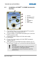
2.3
Anschluss des OGM
Plus
am OGM
Commander-Interface
2
3
4
5
1
6
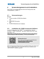
1 Interface
2 Anschluss PC
3 AN / AUS Schalter
4 LED
5
Anschluss OGM
PLUS
6 Netzanschluss
1. Das Interface (Pos 1) wird mit dem PC-Verbindungskabel mit
einer freien COM-Schnittstelle des PC´s verbunden.
2.
OGM
Plus
mit OGM-Verbindungskabel am OGM Commander
(Pos. 5) verbinden.
3. Netzteil mit dem Stromnetz (230V/50Hz) verbinden.
4. Netzteil am OGM Commander-Interface anschließen (Pos. 6).
5. Nach dem Einschalten des OGM Commander-Interface
(Pos. 3), leuchtet die LED (Pos. 4) auf, wenn eine Verbindung
erkannt wurde.
HINWEIS!
Falls die LED nicht leuchtet, liegt ein Fehler in
der Verbindung vor. In diesem Fall alle
Verbindungen auf korrekten Sitz und auch die
Stromquelle überprüfen.
Verwendungszweck und Installation
4Rev. 01-01.2020

2.4 Konfiguration der OGM Commander-Software
HINWEIS!
Die Software ist nur in englischer Sprache
verfügbar!
Um mit dem OGM
Plus
kommunizieren zu können
muss die richtige COM-Schnittstelle (Abb. 1 , Pos. 9)
in der Software eingestellt sein!
1
2
3
4
5
6
7
8
9
10
11
12
A
13
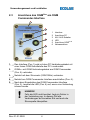
Abb. 1: Konfiguration der OGM Commander-Software
1 Anzeige des ausgelesenen Typs
2 Umschaltung der Augangspolarität
der SPS Impulse
3 Neue Kalibrierung starten
4 Konfiguration auf PC Speichern
5 Konfiguration von PC laden
6 Impulshäufigkeit ul/pulse
7 Anzahl der Impulse pro Umdrehung
8 Anzahl der Umdrehungen pro
Impulse
9 COM-Schnittstelle des PCs
10
Daten aus dem OGM
Plus
auslesen
11
Daten an das OGM
Plus
senden
12 Anzahl der Kalibrierungen
13 Software beenden
A Auswahl der Impulsanzeige
Verwendungszweck und Installation
5 Rev. 01-01.2020

1. COM Port des angeschlossenen OGM Commanders
Auswählen (Pos. 9).
2.
Voreingestellte Einstellungen des OGM
PLUS
durch Drücken der
[Receive] Taste (Abb. 1 , Pos. 10) auslesen.
ð
Der OGM Typ (Pos. 1), die Ausgangspolarität (Pos. 2) und
die Kalibrierungen (Pos. 12) werden ausgelesen und
angezeigt.
3. Konfiguration wie gewünscht anpassen.
ð
Die Darstellung der Impulse kann angepasst werden:
n Umschaltung der Augangspolarität der SPS Impulse
(highside (PNP) oder lowside (NPN))
n Impulshäufigkeit ul/Impulse (Pos. 6)
n Anzahl der Impulse pro Umdrehung (Pos. 7) oder
Umdrehungen pro Impulse (Pos. 8).
4.
Mit [send] Taste (Pos. 11) geänderte Einstellungen an OGM
Plus
senden.
5. Mit [save] Taste (Pos. 4) Konfiguration auf dem PC speichern.
ð
Mit der [load] Taste (Pos. 5) können gespeicherte
Konfigurationen vom PC geladen werden.
2.5 Kalibrierung
Dieser Parameter wird aus dem Kalibriervorgang errechnet. Um eine
Kalibrierung durchführen zu können, muss der OGM
Plus
richtig in Ihr
Dosiersystem eingebaut sein. Die Bedingungen während der
Kalibrierung müssen identisch den Arbeitsbedingungen sein (Druck,
Temperatur, etc.). Mit einem gültigen Kalibrierwert kann genau
festgelegt werden, nach welcher Durchflussmenge Impulse
ausgegeben werden sollen.
Für die Einstellungen Impulse pro Umdrehung
(pulses per rotation) oder Umdrehungen pro Impuls
(rotations per pulse) ist keine gültige Kalibrierung
notwendig.
Verwendungszweck und Installation
6Rev. 01-01.2020

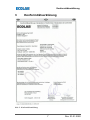
3 Konformitätserklärung
Abb. 2: Konformitätserklärung
Konformitätserklärung
7 Rev. 01-01.2020

1 Scope of supply
Illustration Description
n OGM Commander Interface
n Power supply unit
n Connection cable
between OGM
PLUS
and OGM
n Connection cable
between OGM Commander and PC
(COM-Port)
n Operating Instructions
(Art. No. 417101260)
The latest and complete operating instructions
are made available on the Internet:
https://www.ecolab-engineering.de/fileadmin/
download/bedienungsanleitungen/mess-und-
regeltechnik/Ovalradz-hler-OGM-/
417101260_OGM_Commander_Interface.pdf
Scope of supply
2Rev. 01-01.2020

2 Intended use and installation
The OGM Commander Interface is used to configure the oval gear
meter ‘OGM
PLUS
’ .
2.1 Premises
PC with:
n 1 free serial (COM) Port
or
n USB-RS232 converter
or
n PCMCIA-Plug in card (for laptops)
2.2 Installation of OGM Commander-Software
To configure the OGM
PLUS
, the software: ‘OGM Commander’ is
required. This can be downloaded under the following link:
https://www.ecolab-engineering.de/fileadmin/download/software/
OGM-Software/OGMCommander_1004.zip.
Software download:
https://www.ecolab-engineering.de/fileadmin/
download/software/OGM-Software/
OGMCommander_1004.zip
After successful download of the packed file it must be unpacked on
the PC to be used and installed by executing the ‘SETUP.EXE’ .
Intended use and installation
3 Rev. 01-01.2020

2.3
Installation of OGM
Plus
at OGM Commander-
Interface
2
3
4
5
1
6
1 Interface
2 Connection to PC
3 ON / OFF Switch
4 LED
5
Connection to
OGM
PLUS
6 Power supply
1. The interface (Pos 1) is connected with the PC connection
cable to a free COM interface of the PC.
2.
Connect OGM
Plus
to the OGM Commander (pos. 5) with the
OGM connection cable.
3. Connect the power supply unit to the mains supply
(230V/50Hz).
4. Connect the power supply unit to the OGM Commander
interface (item 6).
5. After switching on the OGM Commander Interface (pos. 3),
the LED (pos. 4) lights up if a connection has been detected.
NOTICE!
If the LED does not light up, there is an error in
the connection. In this case check all
connections for correct fit and also check the
power source.
Intended use and installation
4Rev. 01-01.2020

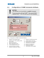
2.4 Configuration of OGM Commander-Software
NOTICE!
The software is only available in english language!
To communicate with the OGM
Plus
, the correct COM
interface (Fig. 1 , Pos. 9) must be set in the software!
1
2
3
4
5
6
7
8
9
10
11
12
A
13
Fig. 1: Configuration of OGM Commander-Software
1 Display of the detected type
2 Switching the output polarity of the
PLC pulses
3 Start new calibration
4 Safe configuration at PC
5 Load configuration from PC
6 Impulse frequency ul/pulse
7 Number of pulses per rotation
8 Number of rotations per pulse
9 COM interface of the PC
10
Read data from the OGM
Plus
11
Send data to the OGM
Plus
12 Number of calibrations
13 Exiting the software
A Selecting the pulse display
Intended use and installation
5 Rev. 01-01.2020

1. Select the COM port of the connected OGM Commander
(pos. 9).
2.
Read the preset settings of the OGM
PLUS
by pressing the
[receive] button (Fig. 1 , pos. 10).
ð
The OGM type (pos. 1), the output polarity (pos. 2) and the
calibrations (pos. 12) are read out and displayed.
3. Adjust the configuration as desired.
ð
The display of the pulses can be adjusted:
n Switching the output polarity of the PLC pulses
(highside (PNP) or lowside (NPN))
n Pulse frequency ul/pulses (pos. 6)
n Number of pulses per revolution (pos. 7) or revolutions
per pulse (pos. 8).
4. Press [send] button (pos. 11) to send changed settings to
OGM
Plus
.
5. Use the [save] button (pos. 4) to save configuration on the PC.
ð
With the [load] button (pos. 5) saved configurations can be
loaded from the PC.
2.5 Calibration
This parameter is calculated from the calibration procedure.
To perform a calibration, the OGM
Plus
must be correctly installed in
your dosing system. The conditions during calibration must be
identical to the working conditions (pressure, temperature, etc.).
With a valid calibration value, it is possible to determine exactly after
which flow rate pulses should be output.
No valid calibration is required for the settings pulses
per rotation or rotations per pulse.
Intended use and installation
6Rev. 01-01.2020

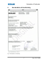
3 Declaration of Conformity
Fig. 2: Declaration of Conformity
Declaration of Conformity
7 Rev. 01-01.2020

Dokumenten-Nr.:
document no.:
Erstelldatum:
date of issue:
Version / Revision:
version / revision:
Letze Änderung:
last changing:
Copyright
Ecolab Engineering GmbH
, 2020
Alle Rechte vorbehalten
All rights reserved
Nachdruck, auch auszugsweise, nur mit Genehmigung
der Firma
Ecolab Engineering GmbH
417101260417101260
30.01.2020
Rev. 01-01.2020
30.01.2020
Reproduction, also in part, only with permission of
Ecolab Engineering GmbH
-
 1
1
-
 2
2
-
 3
3
-
 4
4
-
 5
5
-
 6
6
-
 7
7
-
 8
8
-
 9
9
-
 10
10
-
 11
11
-
 12
12
-
 13
13
-
 14
14


Ecolab OGM PLUS Configuration manual
- Typ
- Configuration manual
- Dieses Handbuch eignet sich auch für
in anderen Sprachen
- English: Ecolab OGM PLUS
Andere Dokumente
-
Topcom deskmaster 125 Benutzerhandbuch
-
SWITEL DET0873 Bedienungsanleitung
-
-
-
EDENWOOD ANDROID ED32C00HD-VE Bedienungsanleitung
-
-
AUDIOLINE WAVE 18 Series Bedienungsanleitung
-
AUDIOLINE WAVE 18 Series Bedienungsanleitung
-
-