
Dell Energy Smart Rack
Enclosure
Installation Guide
Guide d'installation
Installationsanleitung
設置ガイド
Guía de instalación


Dell Energy Smart Rack
Enclosure
Installation Guide

Notes, Cautions, and Warnings
NOTE: A NOTE indicates important information that helps you make better use of
your computer.
CAUTION: A CAUTION indicates potential damage to hardware or loss of data if
instructions are not followed.
WARNING: A WARNING indicates a potential for property damage,
personal injury, or death.
____________________
Information in this publication is subject to change without notice.
© 2011 Dell Inc. All rights reserved.
Reproduction of these materials in any manner whatsoever without the written permission of Dell Inc.
is strictly forbidden.
Trademarks used in this text: Dell™, the DELL logo, and PowerEdge™ are trademarks of Dell Inc.
Other trademarks and trade names may be used in this publication to refer to either the entities claiming
the marks and names or their products. Dell Inc. disclaims any proprietary interest in trademarks and
trade names other than its own.
2011-04 P/N GY60R Rev. A00

Contents 3
Contents
Safety Instructions. . . . . . . . . . . . . . . . . . . . . 5
SAFETY: Rack Mounting of Systems
. . . . . . . . . 5
Rack Installation Instructions
. . . . . . . . . . . . . . . 6
Rack Specifications
. . . . . . . . . . . . . . . . . 6
Before You Begin
. . . . . . . . . . . . . . . . . . . 7
Recommended Tools and Supplies
. . . . . . . . . . 8
Installing Rack Cabinets
. . . . . . . . . . . . . . . 8
Opening and Closing the Front Rack Door
. . . . . . 9
Removing and Replacing the Rack Doors
. . . . . . 9
Removing and Replacing the Side Panels
. . . . . 13
Installing the Brushes
. . . . . . . . . . . . . . . 16
Removing and Replacing the Extension
Service Cover
. . . . . . . . . . . . . . . . . . . . 18
Removing and Replacing the Extension
. . . . . . 20
Reversing the Front Door (Optional)
. . . . . . . . 21
Securing the Rack Leveling Feet
. . . . . . . . . . 29
Installing the Rack Stabilizer Feet
. . . . . . . . . 31
Adjusting the Rear Rack Posts (Optional)
. . . . . 34
Routing Cables
. . . . . . . . . . . . . . . . . . . 36
Coupling Two Racks
. . . . . . . . . . . . . . . . . . . 41

4 Contents

Installation Guide 5
Safety Instructions
Use the following safety guidelines to ensure your own personal safety and to
protect your equipment and working environment from potential damage.
For complete safety and regulatory information, see the safety instructions
that shipped with your equipment. Warranty information may be included in
this document or as a separate document.
SAFETY: Rack Mounting of Systems
Observe the following precautions for rack stability and safety. Also see the
rack installation documentation accompanying the system and the rack for
specific caution statements and procedures.
Systems are considered to be components in a rack. Component refers to any
system as well as to various peripherals or supporting hardware.
CAUTION: Instructions for Rack-Mounted Systems:
• Your rack kit has been approved only for the rack cabinet provided.
It is your responsibility to ensure that installation of the equipment
into any other rack complies with all applicable standards. Dell disclaims
all liability and warranties with respect to combinations of equipment
with any other rack.
• The rack enclosure is cooled by air through the vented tiles of a raised
floor. The rack enclosure should be positioned over the vented tiles before
installing components in the enclosure.
• Before installing your equipment in a rack, ensure that the rack is properly
secured as directed in "Installing the Rack Stabilizer Feet" on page 31.
• Always load from the bottom up and load the heaviest items first.
• Do not overload the AC power supply branch circuit that provides
power to the rack.
• Do not stand or step on any components in the rack.

6 Installation Guide
• The air channel located at the bottom of the rack is used to direct cool air
from the floor to the front of the rack enclosure. The air channel must
always
remain at the bottom of the rack (in 1U and 2U) and must not be
moved to a different location in the rack.
• Do not use the air channel as a step or as a shelf to support components.
WARNING: All brushes supplied must be installed and the brush bristles must be
in contact with the floor to form a seal around the bottom perimeter of the rack
enclosure. Removing the brushes may reduce the cooling efficiency within the
enclosure.
WARNING: The extension service cover must only be removed when installing or
removing components from the upper rack unit spaces and must be reinstalled
immediately. Components in the rack may overheat if the extension service cover
is not installed in the rack enclosure.
Rack Installation Instructions
This installation guide provides instructions for trained service technicians
installing a rack enclosure. Information includes assembling the rack,
coupling two racks, and routing cables through the rack. The rack can be
installed using the recommended tools.
Before attempting this installation, read through this entire procedure carefully.
Rack Specifications
NOTE: The rack meets the specifications of American National Standards Institute
(ANSI), Electronics Components Association (ECA) Standard EIA/ECA-310-E,
International Electrotechnical Commission (IEC) 60297-3-100, and Deutsche Industrie
Norm (DIN) 41494.

Installation Guide 7
Before You Begin
WARNING: Before you begin installing your rack, carefully read "Important
Safety Information" on page 7 and the safety instructions that came with the rack.
WARNING: When installing multiple systems in a rack, complete all the
procedures for the current system before attempting to install the next system.
WARNING: Rack cabinets can be extremely heavy and can move easily on the
casters. The cabinet has no brakes. Use extreme caution while moving the rack
cabinet. Retract the leveling feet when relocating the rack cabinet. Avoid long or
steep inclines, rough surfaces, or ramps where loss of cabinet control may occur.
Extend the leveling feet for support and to prevent the cabinet from rolling.
WARNING: Avoid rolling the rack cabinet over rough surfaces. Hard impacts to
the casters could cause them to break and the rack can become unstable and may
tip over.
WARNING: Do not attempt to move your rack with components installed. If you
move a fully loaded rack on a slightly uneven surface, the rack can become
unstable and may tip over.
Important Safety Information
Observe the safety precautions in the following subsections when installing
your system in the rack.
WARNING: You must strictly follow the procedures in this document to protect
yourself as well as others who may be involved. Your system may be very large
and heavy and proper preparation and planning are important to prevent injury
to yourself and to others. This becomes increasingly important when systems
are installed high up in the rack. Also verify that the vented tiles and floor sub-
structure are rated to support the weight of the rack enclosure with all the
components installed.
WARNING: Before installing systems in a rack, install front and side stabilizers
on stand-alone racks or the front stabilizers on racks joined to other racks.
Failure to install stabilizers accordingly before installing systems in a rack
could cause the rack to tip over, potentially resulting in bodily injury under certain
circumstances.
WARNING: After installing systems in a rack, never pull more than one system
out of the rack on its slide assemblies at one time. The weight of more than one
extended system could cause the rack to tip over and cause injury.

8 Installation Guide
Recommended Tools and Supplies
You may need the following tools and supplies to install the rack:
• #2 Phillips cross-tip screwdriver
• Flat head screwdriver
• 12 mm wrench
• 10 mm wrench (for reversing the front door)
• T20 Torx screwdriver (for reversing the front door)
• T30 Torx screwdriver (for reversing the front door)
• Keys to the rack doors and side panels
• 6 mm Allen wrench
• Adjustable wrench (for removing the rack from the pallet)
Installing Rack Cabinets
Installing a rack cabinet may involve:
1
Opening and closing the front rack door
2
Removing and replacing the rack doors
3
Removing and replacing the side panels
4
Installing the brushes
5
Removing and replacing the extension service cover
6
Removing and replacing the extension
7
Reversing the front door
8
Securing the rack leveling feet
9
Installing the rack stabilizer feet
10
Adjusting the rear rack posts
11
Routing cables
12
Coupling two racks

Installation Guide 9
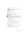
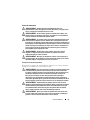
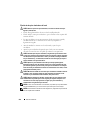
Opening and Closing the Front Rack Door
To open the front rack door:
1
Press in on the handle lock cylinder where the key is inserted. See Figure 1.
2
After the handle is released, pull it upwards to release the door from the
catches. See Figure 1.
3
Open the front door all the way. See Figure 1.
To close the door:
1
Push the door frame evenly against the extension frame and ensure that
the door is in contact with the extension frame.
2
Push the handle down to latch the door.
Removing and Replacing the Rack Doors
WARNING: Never attempt to remove or install the rack cabinet doors by yourself.
Due to the size and weight of the rack cabinet doors, this procedure requires at
least two people.
Removing the Front Door
1
Open the rack door. See "Opening and Closing the Front Rack Door" on
page 9.
2
While holding the door, remove the hinge pins starting from the bottom of the
rack. Ensure that the top hinge pin is the last pin to be removed from the door.
To remove the hinge pin:
a
Pull the hinge pin so that it clears the hinge-pin housing on the door.
For the hinge pins located at the bottom of the door, pull the two
hinge pins downward. For the hinge pins located at the top of the
door, pull the two hinge pins upward. See Figure 1.
The hinge pin's retention clip prevents the hinge from being
completely pulled out of the hinge body.
b
Pull the door slightly away from the rack so that the door clears the
hinge body.
WARNING: When storing the doors, lay the doors flat so they do not fall over
and accidentally injure someone.
WARNING: Due to the size and weight of the door, it is recommended that you lay
the removed door flat with its outer surface facing upward.
3
Lay the door in a safe location with the door's outer surface facing upward
to prevent damage to the door's badge and cosmetic coating.

10 Installation Guide
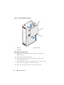
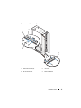
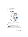
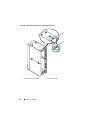
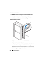
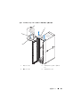
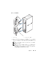
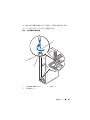
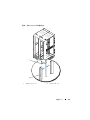
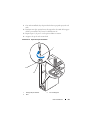
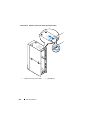
Figure 1. Removing the Front Door
Replacing the Front Door
To replace the front door, follow the steps for removing the front door in the
reverse order.
1 handle 2 hinge pins (4)
3 hinge body 4 hinge-pin housings (4)
5 lock cylinder
1
3
5
4
2

Installation Guide 11
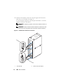
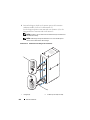
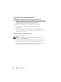
Removing the Back Doors
WARNING: Never attempt to remove or install the rack cabinet doors by yourself.
Due to the size and weight of the rack cabinet doors, this procedure requires
two people.
1
Rotate the door handle one-quarter turn clockwise to open the back doors.
See Figure 2.
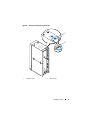
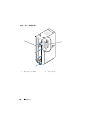
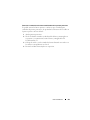
Figure 2. Opening the Back Doors
1 door handle 2 back doors (2)
2
1

12 Installation Guide
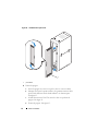
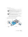
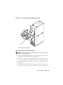
2
Remove the right back door.
a
While supporting the door, pull the pin for the top hinge out of the
door’s hinge-pin housing. See Figure 3.
You hear a click sound as you pull the pin out of the door’s hinge-pin
housing. The hinge pins are designed to prevent them from being pulled
out of the hinge body.
b
Repeat step a for the bottom hinge.
c
Pull the door away from the rack.
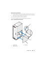
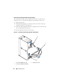
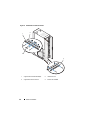
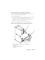
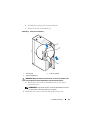
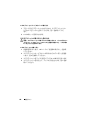
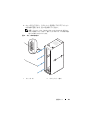
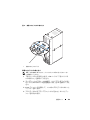
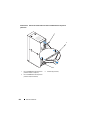
Figure 3. Removing the Back Doors
WARNING: Due to the size and weight of the door, it is recommended that you lay
the removed door flat with its outer surface facing upward.
1 hinge pin 2 hinge body
3 hinge-pin housing
1
2
3

Installation Guide 13
d
Lay the door in a safe location with the door’s outer surface
facing upward.
NOTE: Lay the door flat with the outer surface facing upward to prevent
damage to its cosmetic coating.
3
Repeat step a through step d for the left back door.
Replacing the Back Doors
To replace the back doors, follow the steps for removing the back doors in the
reverse order.
Removing and Replacing the Side Panels
NOTE: Remove the lower side panels in order to install the side brushes and the
side stabilizer feet.
NOTE: Although removing the side panels is not mandatory for installing
systems in a rack, having the sides open makes it easier to install slide assemblies
and support rails and to reverse the direction that the front door opens.
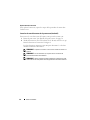
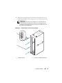
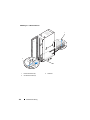
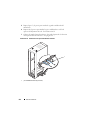
Removing the Upper Side Panels
1
Push both latches up and swing the bottom end of the panel away
from the rack. See Figure 4.
2
Grasp firmly on each side of the panel.
3
Lift the panel upward until the panel lip clears the top of the rack.
4
Lay the panel in a safe location with the panel’s outer surface facing
upward to prevent damage to its cosmetic coating.
5
Repeat step 1 through step 4 for the other upper side panel.
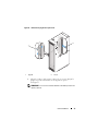
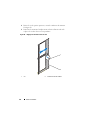
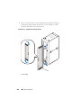
Replacing the Upper Side Panels
1
Lift the upper side panel up onto the rack, hooking the panel lip over the
top of the rack. See Figure 4.
2
Swing the bottom of the panel downward onto the rack.
3
Press the panel into the rack until both latches lock into place.

14 Installation Guide
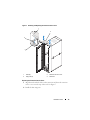
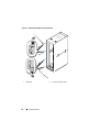
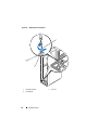
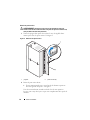
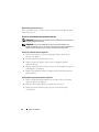
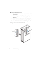
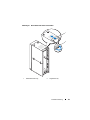
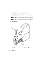
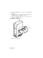
Figure 4. Replacing the Upper Side Panels
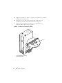
Removing the Lower Side Panels
1
Pull both latches down and allow the side panel to swing outward
slightly at the top.
2
Firmly grasp both sides of the panel.
3
Lift the panel upward until the panel hooks clear the holes in the
bottom of the rack frame.
4
Place the panel in a safe location with the panel’s outer surface facing
upward to prevent damage to its cosmetic coating.
5
Repeat step 1 through step 4 for the other lower side panel.
1 panel lip 2 upper side panel
3 latches (2)
2
3
1

Installation Guide 15
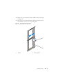
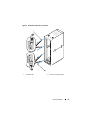
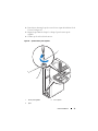
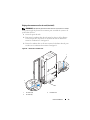
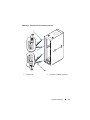
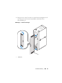
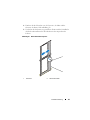
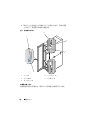
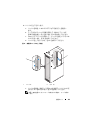
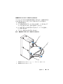
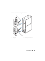
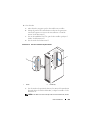
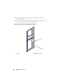
Replacing the Lower Side Panels
1
Lower the panel into the rack, inserting the panel hook into the back hole
in the bottom of the rack frame and the front hook into the corresponding
hole in the front of the rack frame. See Figure 5.
2
Swing the top end of the panel toward the rack.
3
Press the panel into the rack until both latches lock into place.
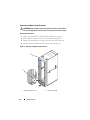
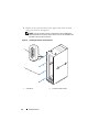
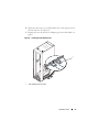
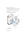
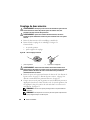
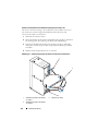
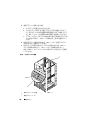
Figure 5. Replacing the Lower Side Panels
1 panel hooks (2) 2 latches (2)
3 lower side panel
1
2
3

16 Installation Guide
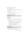
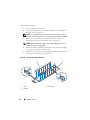
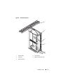
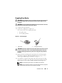
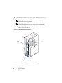
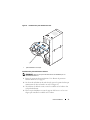
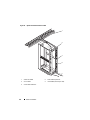
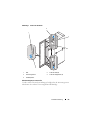
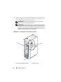
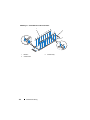
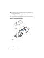
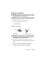
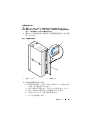
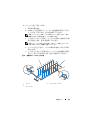
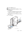
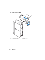
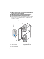
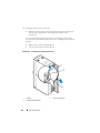
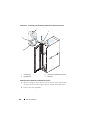
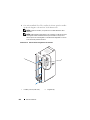
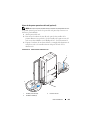
Installing the Brushes
WARNING: All brushes supplied must be installed and the brush bristles must be
in contact with the floor to form a seal around the bottom perimeter of the rack
enclosure. Removing the brushes may reduce the cooling efficiency within the
enclosure.
To install the brushes on the side of the rack:
1
Remove the lower side panel. See "Removing the Lower Side Panels" on
page 14.
2
Align the brush bracket with the rack frame and insert the brush bracket
into the rack frame. See Figure 6.
3
Secure the brush bracket using the four bolts and washers. See Figure 6.
4
Replace the lower side panel. See "Replacing the Lower Side Panels" on
page 15.
5
Repeat step 1 through step 4 for the other side of the rack.
To install the brush at the back of the rack:
1
Rotate the door handle one-quarter turn clockwise to open the back doors.
See Figure 2.
2
Align the brush bracket with the rack frame and insert the brush bracket
into the rack frame. See Figure 6.
3
Secure the brush bracket using the two bolts and washers. See Figure 6.
4
Close the back door.

Installation Guide 17
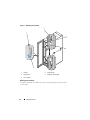
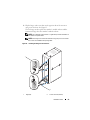
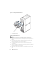
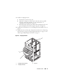
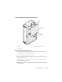
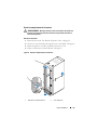
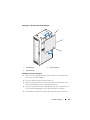
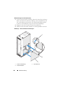
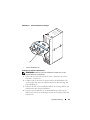
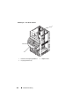
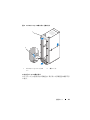
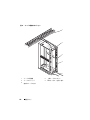
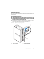
Figure 6. Installing and Removing the Brushes
1 side brush brackets (2) 2 rack frame
3 back brush bracket 4 bolts and washers
4
1
2
3

18 Installation Guide
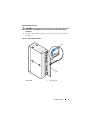
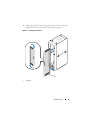
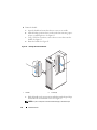
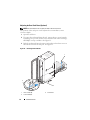
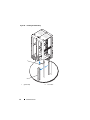
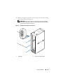
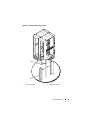
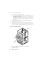
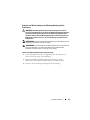
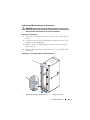
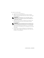
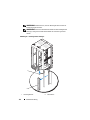
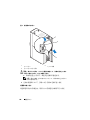
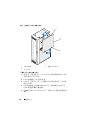
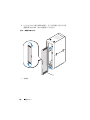
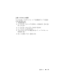
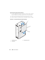
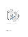
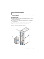
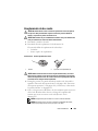
Removing and Replacing the Extension Service Cover
WARNING: The extension service cover must only be removed when installing or
removing components from the upper rack unit spaces and must be reinstalled
immediately. Components in the rack may overheat if the extension service cover
is not installed in the rack enclosure.
NOTE: Do not use the extension service cover as an outlet to route cables out of
the rack.
NOTE: Removing the extension service cover allows you to install and service the
equipment in the upper rack unit spaces more easily.
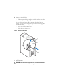
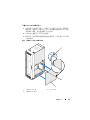
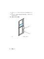
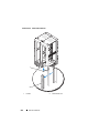
Removing the Extension Service Cover
1
Loosen and remove the four wing nuts located on the top surface inside of
the extension. See Figure 7.
2
Lift the extension service cover until the studs clear the holes in the extension.
3
Remove the extension service cover.
Seite wird geladen ...
Seite wird geladen ...
Seite wird geladen ...
Seite wird geladen ...
Seite wird geladen ...
Seite wird geladen ...
Seite wird geladen ...
Seite wird geladen ...
Seite wird geladen ...
Seite wird geladen ...
Seite wird geladen ...
Seite wird geladen ...
Seite wird geladen ...
Seite wird geladen ...
Seite wird geladen ...
Seite wird geladen ...
Seite wird geladen ...
Seite wird geladen ...
Seite wird geladen ...
Seite wird geladen ...
Seite wird geladen ...
Seite wird geladen ...
Seite wird geladen ...
Seite wird geladen ...
Seite wird geladen ...
Seite wird geladen ...
Seite wird geladen ...
Seite wird geladen ...
Seite wird geladen ...
Seite wird geladen ...
Seite wird geladen ...
Seite wird geladen ...
Seite wird geladen ...
Seite wird geladen ...
Seite wird geladen ...
Seite wird geladen ...
Seite wird geladen ...
Seite wird geladen ...
Seite wird geladen ...
Seite wird geladen ...
Seite wird geladen ...
Seite wird geladen ...
Seite wird geladen ...
Seite wird geladen ...
Seite wird geladen ...
Seite wird geladen ...
Seite wird geladen ...
Seite wird geladen ...
Seite wird geladen ...
Seite wird geladen ...
Seite wird geladen ...
Seite wird geladen ...
Seite wird geladen ...
Seite wird geladen ...
Seite wird geladen ...
Seite wird geladen ...
Seite wird geladen ...
Seite wird geladen ...
Seite wird geladen ...
Seite wird geladen ...
Seite wird geladen ...
Seite wird geladen ...
Seite wird geladen ...
Seite wird geladen ...
Seite wird geladen ...
Seite wird geladen ...
Seite wird geladen ...
Seite wird geladen ...
Seite wird geladen ...
Seite wird geladen ...
Seite wird geladen ...
Seite wird geladen ...
Seite wird geladen ...
Seite wird geladen ...
Seite wird geladen ...
Seite wird geladen ...
Seite wird geladen ...
Seite wird geladen ...
Seite wird geladen ...
Seite wird geladen ...
Seite wird geladen ...
Seite wird geladen ...
Seite wird geladen ...
Seite wird geladen ...
Seite wird geladen ...
Seite wird geladen ...
Seite wird geladen ...
Seite wird geladen ...
Seite wird geladen ...
Seite wird geladen ...
Seite wird geladen ...
Seite wird geladen ...
Seite wird geladen ...
Seite wird geladen ...
Seite wird geladen ...
Seite wird geladen ...
Seite wird geladen ...
Seite wird geladen ...
Seite wird geladen ...
Seite wird geladen ...
Seite wird geladen ...
Seite wird geladen ...
Seite wird geladen ...
Seite wird geladen ...
Seite wird geladen ...
Seite wird geladen ...
Seite wird geladen ...
Seite wird geladen ...
Seite wird geladen ...
Seite wird geladen ...
Seite wird geladen ...
Seite wird geladen ...
Seite wird geladen ...
Seite wird geladen ...
Seite wird geladen ...
Seite wird geladen ...
Seite wird geladen ...
Seite wird geladen ...
Seite wird geladen ...
Seite wird geladen ...
Seite wird geladen ...
Seite wird geladen ...
Seite wird geladen ...
Seite wird geladen ...
Seite wird geladen ...
Seite wird geladen ...
Seite wird geladen ...
Seite wird geladen ...
Seite wird geladen ...
Seite wird geladen ...
Seite wird geladen ...
Seite wird geladen ...
Seite wird geladen ...
Seite wird geladen ...
Seite wird geladen ...
Seite wird geladen ...
Seite wird geladen ...
Seite wird geladen ...
Seite wird geladen ...
Seite wird geladen ...
Seite wird geladen ...
Seite wird geladen ...
Seite wird geladen ...
Seite wird geladen ...
Seite wird geladen ...
Seite wird geladen ...
Seite wird geladen ...
Seite wird geladen ...
Seite wird geladen ...
Seite wird geladen ...
Seite wird geladen ...
Seite wird geladen ...
Seite wird geladen ...
Seite wird geladen ...
Seite wird geladen ...
Seite wird geladen ...
Seite wird geladen ...
Seite wird geladen ...
Seite wird geladen ...
Seite wird geladen ...
Seite wird geladen ...
Seite wird geladen ...
Seite wird geladen ...
Seite wird geladen ...
Seite wird geladen ...
Seite wird geladen ...
Seite wird geladen ...
Seite wird geladen ...
Seite wird geladen ...
Seite wird geladen ...
Seite wird geladen ...
Seite wird geladen ...
Seite wird geladen ...
Seite wird geladen ...
Seite wird geladen ...
Seite wird geladen ...
Seite wird geladen ...
Seite wird geladen ...
Seite wird geladen ...
Seite wird geladen ...
Seite wird geladen ...
Seite wird geladen ...
Seite wird geladen ...
Seite wird geladen ...
Seite wird geladen ...
Seite wird geladen ...
Seite wird geladen ...
Seite wird geladen ...
Seite wird geladen ...
Seite wird geladen ...
Seite wird geladen ...
Seite wird geladen ...
Seite wird geladen ...
Seite wird geladen ...
Seite wird geladen ...
Seite wird geladen ...
Seite wird geladen ...
Seite wird geladen ...
Seite wird geladen ...
Seite wird geladen ...
Seite wird geladen ...
Seite wird geladen ...
Seite wird geladen ...
Seite wird geladen ...
Seite wird geladen ...
Seite wird geladen ...
Seite wird geladen ...
Seite wird geladen ...
-
 1
1
-
 2
2
-
 3
3
-
 4
4
-
 5
5
-
 6
6
-
 7
7
-
 8
8
-
 9
9
-
 10
10
-
 11
11
-
 12
12
-
 13
13
-
 14
14
-
 15
15
-
 16
16
-
 17
17
-
 18
18
-
 19
19
-
 20
20
-
 21
21
-
 22
22
-
 23
23
-
 24
24
-
 25
25
-
 26
26
-
 27
27
-
 28
28
-
 29
29
-
 30
30
-
 31
31
-
 32
32
-
 33
33
-
 34
34
-
 35
35
-
 36
36
-
 37
37
-
 38
38
-
 39
39
-
 40
40
-
 41
41
-
 42
42
-
 43
43
-
 44
44
-
 45
45
-
 46
46
-
 47
47
-
 48
48
-
 49
49
-
 50
50
-
 51
51
-
 52
52
-
 53
53
-
 54
54
-
 55
55
-
 56
56
-
 57
57
-
 58
58
-
 59
59
-
 60
60
-
 61
61
-
 62
62
-
 63
63
-
 64
64
-
 65
65
-
 66
66
-
 67
67
-
 68
68
-
 69
69
-
 70
70
-
 71
71
-
 72
72
-
 73
73
-
 74
74
-
 75
75
-
 76
76
-
 77
77
-
 78
78
-
 79
79
-
 80
80
-
 81
81
-
 82
82
-
 83
83
-
 84
84
-
 85
85
-
 86
86
-
 87
87
-
 88
88
-
 89
89
-
 90
90
-
 91
91
-
 92
92
-
 93
93
-
 94
94
-
 95
95
-
 96
96
-
 97
97
-
 98
98
-
 99
99
-
 100
100
-
 101
101
-
 102
102
-
 103
103
-
 104
104
-
 105
105
-
 106
106
-
 107
107
-
 108
108
-
 109
109
-
 110
110
-
 111
111
-
 112
112
-
 113
113
-
 114
114
-
 115
115
-
 116
116
-
 117
117
-
 118
118
-
 119
119
-
 120
120
-
 121
121
-
 122
122
-
 123
123
-
 124
124
-
 125
125
-
 126
126
-
 127
127
-
 128
128
-
 129
129
-
 130
130
-
 131
131
-
 132
132
-
 133
133
-
 134
134
-
 135
135
-
 136
136
-
 137
137
-
 138
138
-
 139
139
-
 140
140
-
 141
141
-
 142
142
-
 143
143
-
 144
144
-
 145
145
-
 146
146
-
 147
147
-
 148
148
-
 149
149
-
 150
150
-
 151
151
-
 152
152
-
 153
153
-
 154
154
-
 155
155
-
 156
156
-
 157
157
-
 158
158
-
 159
159
-
 160
160
-
 161
161
-
 162
162
-
 163
163
-
 164
164
-
 165
165
-
 166
166
-
 167
167
-
 168
168
-
 169
169
-
 170
170
-
 171
171
-
 172
172
-
 173
173
-
 174
174
-
 175
175
-
 176
176
-
 177
177
-
 178
178
-
 179
179
-
 180
180
-
 181
181
-
 182
182
-
 183
183
-
 184
184
-
 185
185
-
 186
186
-
 187
187
-
 188
188
-
 189
189
-
 190
190
-
 191
191
-
 192
192
-
 193
193
-
 194
194
-
 195
195
-
 196
196
-
 197
197
-
 198
198
-
 199
199
-
 200
200
-
 201
201
-
 202
202
-
 203
203
-
 204
204
-
 205
205
-
 206
206
-
 207
207
-
 208
208
-
 209
209
-
 210
210
-
 211
211
-
 212
212
-
 213
213
-
 214
214
-
 215
215
-
 216
216
-
 217
217
-
 218
218
-
 219
219
-
 220
220
-
 221
221
-
 222
222
-
 223
223
-
 224
224
-
 225
225
-
 226
226
-
 227
227
-
 228
228


