
User and Maintenance
Instructions
Induction Cooker
(Electric)
Handleiding Voor
Bediening En
Onderhoud
Inductiekookplaat
(Elektrisch)
Betriebs- und
Wartungsanleitung
Induktionsherd
(Elektrisch)
Manuel d’Utilisation
et de Maintenance
Plaque À
Induction
(Électrique)

2
Table of Contents / Inhoudsopgave /
Inhaltsverzeichnis / Table des Matières
I. ENGLISH ………………………………………………………………. 3
A. Description
B. Products
C. Mounting Instructions
D. Operator Instructions and Attention Points
E. Figures
F. Product Drawings
G. Electrical Connection Drawing
II. NEDERLANS ………………………………………………………… 23
A. Beschrijving
B. Producten
C. Montage-Instructies
D. Instructies van de bediener en aandachtspunten
E. Figuur
F. Producttekeningen
G. Elektrische Aansluittekeningen
III. DEUTSCH …………………………………………………………….. 44
A. Beschreibung
B. Produkte
C. Installationsanleitung
D. Benutzerhinweise und zu Beachtende Punkte
E. Abbildung
F. Produktzeichnungen
G. Elektrische Anschlusszeichnung
IV. FRANÇAIS …………………………………………………………… 65
A. Explications
B. Des Produits
C. Instructions de Montage
D. Instructions a L’utilisateur et Points a Considérer
E. Les Figures
F. Dessins des Produits
G. Dessin de connexion électrique

3
User and Maintenance
Instructions
Induction Cooker (Electric)

4
A. DESCRIPTION
Our dear customer,
Your preferred COMBISTEEL is nature and technology friendly. We thank you for your
choice.
COMBISTEEL has been produced with the understanding of "Total Quality" in modern
production facilities.
Important Safety Information
Carefully read this guide and keep it for future review.
WARNING: Installation of the devices must be done by an authorized service person.
WARNING: Equipment must be grounded.
WARNING: If the surface is cracked, immediately disconnect the appliance or appropriate
part of the appliance from the supply.
Indicates that there is a risk of personal injury or property damage.
Explosion / fire hazard
High voltage, be careful when repairing operation, non-professionals do not
disassemble
Induction cooker generates a magnetic field when it is working, pay attention
when operating.
The instructions in this manual contain important information on the safe mounting,
usage, cleaning and maintenance of the device. Thus, keep the manual at a place easily
accessible by the person who will use the machine, and the technician.
Mounting, electrical connection and maintenance works of the device should be
performed by a specialist authorized in this subject and in accordance with the
instructions of the manufacturer company.
Electrical connection of the device should be arranged according to the tables and
electrical diagram given in this manual.
Manufacturer Company accepts no responsibility for the final damages incurred in
humans or properties that are caused by any procedure not conforming to the instruction
manual, or maintenance or technical interventions that are not performed by authorized
people.
The instructions for appliances with hob surfaces of glass-ceramic or similar material
shall state that aluminium foil and plastic vessels are not to be placed on the hot surfaces.
They shall also state that these surfaces are not to be used for storage

5
Metallic objects such as kitchen utensils, cutlery etc. shall not be placed on the hob
surface within the cooking zones since they could get hot;
Take care when operating the appliance, as rings, watches and similar objects worn by
the user could get hot when in close proximity to the hob surface;
Only use vessels of the type and size recommended.
B. PRODUCTS
C. MOUNTING INSTRUCTION
Placement
Installation and adjustment of the device should be carried out by technical staff of the
Authorized Service.
Place the device beneath a filtered exhaust hood in order to eliminate smell and fume
that may be emitted during cooking.
Device should be placed on a flat surface by suitably balancing on the four adjustable
legs. (Figure A)
Remove the protective nylon on the device. Clean the adhesive particles left on the
device with a suitable cleaner.
Leave a space of about 20cm behind the stove to facilitate the fan to dissipate heat.
Electrical Connection
Connect the device to the electrical installation according to the electrical standards of
the relevant country.
Feed the device with suitable network voltage written on the information plate.
CODE
DESCRIPTION
SERIE
7178.0130
Electric induction cooker, tabletop model, 1 round plate
600
7178.0570
Electric induction cooker, 2 round plates
700
7178.0575
Electric induction cooker, 4 round plates
700
7178.0580
Electric wok cooker, 1 round plate
700
7178.0330
Electric induction cooker, tabletop model, 2 round plates
700S
7178.0335
Electric induction cooker, tabletop model, 4 round plates
700S
7178.0340
Electric wok cooker, tabletop model 1 round plate
700S
7178.3140
Electric induction cooker, 2 round plates
900
7178.3145
Electric induction cooker, 4 round plates
900

6
Connect to the electrical installation over a suitable automatic fuse. Fix the said fuse on
a place that is easily accessible in case of a danger.
The cable connecting the device to the electrical installation should be at least type H07
RNF.
Before connecting the electrical inlet cable to the inlet clamp on the device, connect the
cable by passing it through the inlet coupling. And then tighten the coupling cover in a
manner that does not allow cable return.
Electrical inlet is indicated with a label on the device.
If the device will be used in a commercial kitchen, apply a correct grounding system.
Here, consider DIN VDE D100 Article 540.
Grounding screw " " is indicated with a label behind the device.
D. OPERATOR INSTRUCTIONS AND ATTENTION POINTS
The induction cooker is a new type of stove in the kitchen ware market. It breaks the
traditional open flame cooking method. The working principle of electromagnetic
heating is to pass a high-frequency current through the coil disk to generate a magnetic
field on both sides of the coil disk. When the iron pot is within the magnetic field, the
pot cuts the alternating magnetic field lines produce alternating currents in the pot (ie.
eddy current). The eddy current causes the iron molecules of the pot to move randomly
at high speed. The molecules collide with each other and rub against each other to
generate heat energy to make the appliance itself heat up at high speed for heating and
cooking food. So as to achieve the purpose of
BEFORE USE
Electrical system check
After mounting, check the controlling members and heaters by operating at different
temperatures.
After the installation and maintenance, check the heating power of device.
During first operation, device will emit fume and smell for a short period. This fume and
smell is the result of the insulation material and the substances such as oil, etc. on the
metal sheet surfaces. This is not dangerous and will disappear by itself.
STARTING-UP COOKERS
Power on: Turn on the power, the indicator lights are all on, and the digital tube displays
the corresponding model, such as "P350" for 3500W flat-hearth furnace series, "A350"
for 3500W concave furnace series, " P250" for 2500W flat-head furnace series, "A250"
"Means 2500W concave furnace series, "P500" means 5000W flat-top furnace series,
and "A500" means 5000W concave furnace series. "P-15" means 15KW flat-top stove
series, "A-20" means 20KW concave type frying stove series. After about 2S, the
indicator light is off, the power light flashes, and the digital display " ----" indicates the
standby state.

7
TURN ON
After about 2S, the indicator light is off, the power light flashes, and the digital display
"----" indicates the standby state.
Power on: Press the power "switch"(1) button once (Note: When all touch buttons are
operated, press the finger at the center of the corresponding button pattern. Each time
you press it, you should stay for a while, and then let go. Because the button has the
function of preventing misoperation, the button. The action should not be too fast,
otherwise the key will be invalid, the digital display "on", press the "firepower"(2) key
again, the corresponding power will be displayed, the default maximum gear; or press
the "fixed temperature" key once to display the corresponding set temperature, The
default is 200°C. All the indicator lights are on, and it can be heated after putting the pot.
If you press the "Firepower" key during the constant temperature process, it can also be
set to the heating function.
Firepower/Temperature Adjustment: Adjust the appropriate power (firepower) and
temperature through the knob (3). Turn clockwise to increase firepower (temperature),
and turn counterclockwise to decrease firepower (temperature). The gears are divided
into 9 levels (3).

8
Constant Temperature Function: Turn on, press the "fixed temperature" button, or
press the "fixed temperature" button (5) once when the induction cooker is working in
the heating function, the display will show the gear position, such as the digital display
"200C" means 200°C, enter the temperature function, the appropriate temperature can
be adjusted through the knob (6). Clockwise rotation temperature increases, counter
clockwise rotation temperature decreases, and the gears are divided into 9 gears.
TIME SETTING
The timing function can be set for the heating mode or constant temperature mode of the
induction cooker. Firstly press power mode or temperature mode button(8) once, after
press the time button(9) then the number flashes, enter the timing shutdown setting.
When the time key is pressed for the first time
The nixie tube displays "00:00" flashing, indicating that the timing time is 0 minutes
(that is, there is no timing).
The required timing time can be adjusted through the knob(10). The clockwise rotation
time adds 10 minutes, and the counterclockwise rotation time subtracts 1 minute. The
maximum timing time can be set to 23:59. If you do not adjust the knob, it will
automatically confirm after about 5 seconds and enter the countdown. If you press the
"timing" key again within 5 seconds, the timing setting will be cancelled; in addition, the
timing will not work when it displays 00:00.
After the time setting is completed, the timing starts. After the timer is started, the display
will switch back and forth between time and firepower (temperature).

9
SHUT DOWN
During the operation of the induction cooker, press the power switch button (7) once, the
power light flashes, the digital tube displays " --- ", and the other indicator lights are off,
indicating that it enters the standby state.
MAINTENANCE
Do not perform maintenance when the device is loaded with electrical power.
Before it cools down completely, wipe the device with a cloth immersed in warm soapy
water.
Do not use cleaning substances and tools that may cause scratches on device surface.
Do not clean the device with water or vapour pressure. Otherwise, you may cause
electrical plate failure.
If the device will not be used for a long period, coat the surfaces with a thin layer of
Vaseline. In case of any dangerous condition with the device, notify to the authorized
service. Never let unauthorized people to interfere in the device.
Do not perform maintenance when the device is loaded with electrical power.
CONTROL PANEL CHANGE
Remove the front panel with appropriate screwdriver from panel bottom. (11)
Turn the panel to back for easy remove and after remove the panel screws from back
with screw driver. (12)
Remove the control panel cable connection socket with hand from the PCB. (13)
COIL CHANGE
Unscrew the top plate with the appropriate wrench from the inside and turn the top plate
sideways (14)
Remove the coil fixing part screw by suitable wrench (15)
Unscrew the coil connection screw with suitable wrench (16)

10
PCB&FAN CHANGE
Remove the front panel and top table from bottom with suitable wrench (17)
After removing front panel and top table, remove the fan sockets with hand and coil
cables from screws. (18)
CERAMIC GLASS CHANGE
Remove the glass by cleaning the silicon around the ceramic glass.
Clean the surface on which the glass will be attached with a silicone cleaner spray,
squeeze the appropriate silicone and place the glass in the middle.
After placing a suitable weight on it, smooth the overflowing silicones with the plastic
apparatus and wait for it to dry for 12 hours.

11
ATTENTIONS
Dry burning in empty pot is strictly prohibited;
Before the power is disconnected, the induction cooker must be turned off and in a
standby state;
Please disconnect the power if not used for a long time;
When the stove has glass-ceramics, please avoid being hit by hard objects and use
matching pots;
If the glass-ceramic is damaged, please stop using it immediately and disconnect the
power supply;
Please pay attention to waterproofing when cleaning the stove (cannot be cleaned with
jet water);
This induction cooker cannot be used to cook porridge or soy milk, otherwise it will
easily cause dry burning and danger;
The concave cookware used in this stove is matched with the manufacturer. If the user
needs to replace it, please choose the same size and material (iron) as the manufacturer,
or contact the manufacturer to purchase. Otherwise, the firepower may not meet the
requirements, and it may even break the glass and cause danger. Table-top flat pots
should be made of iron pots with a bottom diameter greater than 26cm. Pots with a
diameter less than 33cm should not exceed 10kg in total weight. Pots with a diameter
greater than 33cm should not exceed 20kg in total weight to avoid damage. Glass is
dangerous.
During the use of the stove, metal objects such as kitchen utensils, knives and forks are
not allowed
Put it in the cooking area on the cooktop, otherwise, when it is near the wok (within the
magnetic field), it will automatically heat up and cause danger;
Do not place aluminum foil or plastic containers on a hot surface, and do not stack objects
on the surface of the stove;
During operation, if the operator wears metal (iron) jewelry (rings, bracelets, watches,
etc.) on his hands, the jewelry may automatically heat up when his hands are near the
wok (within the magnetic field). At this time, stop the operation immediately and remove
the accessories.
Users with pacemakers should consult with the manufacturer before operating the stove;
When the stove fails, it can only be repaired by personnel trained or recommended by
the manufacturer.

12
Troubleshooting
Error Code
Failure Phenomenon
Method of Exclusion
''E01'' flashes
IGBT sensor open circuit
1.Check whether the IGBT sensor is open
2.Check whether the IGBT terminal is loose
''E02'' flashes
IGBT sensor short circuit
1.Check whether the IGBT sensor is open
2.Check whether the IGBT terminal is loose
''E03'' flashes
Wire reel sensor open circuit
1.Check whether the IGBT sensor is damaged
2.Check whether the sensor cable is disconnected and
whether there is poor contact.
''E04'' flashes
The wire reel temperature is
high or the wire reel sensor is
short-circuit
1.Check whether the sensor is damaged
2.Check whether the sensor cable is disconnected
3.Check whether the sensor interface is loose
4.Check whether the coil disk cooling fan rotates or the
speed or the speed is too slow
5.Check whether the air inlet or exhaust vent is
blocked.
''E05'' flashes
Furnace sensor open circuit
1.Check whether the sensor cable is disconnected and
whether there is poor contact
''E06'' flashes
Furnace sensor open circuit
1.Check whether the sensor is damaged
2.Check whether the sensor line is short-circuited
''E07'' flashes
Grid voltage is too low
1.For 220V models, check whether the grid voltage is
lower than 150V, and for 380V models, check whether
the grid voltage is lower than 350V
2.Check whether the core power transformer is
damaged
''E08'' flashes
Grid voltage is too high
1.For the 220V models, check whether the grid voltage
is higher than 260V, and for 380V, check whether the
grid voltage is higher than 450V
''F'' flashes
IGBT temperature is too high
1.Check whether the movement fan rotates or the speed
is too slow
2.Check whether the air inlet or exhaust vent is blocked
''E00'' flashes
No pot or inappropriate pot
1.Check whether the wire reel and the wire reel
terminal are loose
2. Check whether the pot is severely deformed
3. Check whether the pot material used is suitable
whether the bottom of the pot is seriously deformed,
and whether the pot is placed in the correct position.

13
Compatibility Information
This device is designed and manufactured in accordance with the following directives and
standards.
marking directive, 93/68/CEE
TS EN 60335-1:2012/AC
TS EN 60335-2:37
Related to CE Directive(s):
2014/35/EU (Low Voltage)
Limitation of Liability: All technical information contained in this manual, operating
instructions, operation and maintenance of the device, contains the latest information on your
device. The manufacturer accepts no responsibility for damage or injury which may result
from failure to follow the instructions in this manual, use outside of the intended use,
unauthorized repair, unauthorized modifications to the device, or use of spare parts not
approved by the manufacturer.
E. FIGURES
Figure A

14
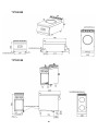
F. PRODUCT DRAWINGS
Product
Width
(W)
Depth
(D)
Height
(H)
Electrical
Inlet
Power
Cable
Sections
Weight
Volume
7178.0130
400 mm
600 mm
300 mm
230V AC
1N PE
3,5 kW
3x1.5
H05RNF
30 kg
0.18 m³
7178.0570
400 mm
700 mm
900 mm
230V AC
1N PE
7 kW
3x2.5
H05RNF
36 kg
0.44
m³
7178.0575
800 mm
700 mm
900 mm
400V AC
3N PE
14 kW
5x4
H05RNF
57 kg
0.84
m³
7178.0580
400 mm
700 mm
900 mm
230V AC
1N PE
5 kW
3x2.5
H05RNF
45 kg
0.44
m³
7178.0330
400 mm
700 mm
300 mm
230V AC
1N PE
7 kW
3x2.5
H05RNF
34 kg
0.21
m³
7178.0335
800 mm
700 mm
300 mm
400V AC
3N PE
14 kW
5x4
H05RNF
52 kg
0.36
m³
7178.0340
400 mm
700 mm
300 mm
230V AC
1N PE
5 kW
3x2.5
H05RNF
29 kg
0.21
m³
7178.3140
400 mm
900 mm
900 mm
400V AC
3N PE
10 kW
5x4
H05RNF
90 kg
0.55
m³
7178.3145
800 mm
900 mm
900 mm
400V AC
3N PE
20 kW
5x4
H05RNF
185 kg
1.05
m³

15
7178.0130
7178.0570

16
7178.0575
7178.0580

17
7178.0330
7178.0335

18
7178.0340
7178.3140

19
7178.3145

20
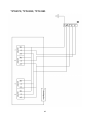
G.ELECTRICAL CONNECTION DRAWING
7178.0130 / 7178.0570 / 7178.0580 / 7178.0330 / 7178.0340 /
7178.3140
Seite laden ...
Seite laden ...
Seite laden ...
Seite laden ...
Seite laden ...
Seite laden ...
Seite laden ...
Seite laden ...
Seite laden ...
Seite laden ...
Seite laden ...
Seite laden ...
Seite laden ...
Seite laden ...
Seite laden ...
Seite laden ...
Seite laden ...
Seite laden ...
Seite laden ...
Seite laden ...
Seite laden ...
Seite laden ...
Seite laden ...
Seite laden ...
Seite laden ...
Seite laden ...
Seite laden ...
Seite laden ...
Seite laden ...
Seite laden ...
Seite laden ...
Seite laden ...
Seite laden ...
Seite laden ...
Seite laden ...
Seite laden ...
Seite laden ...
Seite laden ...
Seite laden ...
Seite laden ...
Seite laden ...
Seite laden ...
Seite laden ...
Seite laden ...
Seite laden ...
Seite laden ...
Seite laden ...
Seite laden ...
Seite laden ...
Seite laden ...
Seite laden ...
Seite laden ...
Seite laden ...
Seite laden ...
Seite laden ...
Seite laden ...
Seite laden ...
Seite laden ...
Seite laden ...
Seite laden ...
Seite laden ...
Seite laden ...
Seite laden ...
Seite laden ...
Seite laden ...
Seite laden ...
-
 1
1
-
 2
2
-
 3
3
-
 4
4
-
 5
5
-
 6
6
-
 7
7
-
 8
8
-
 9
9
-
 10
10
-
 11
11
-
 12
12
-
 13
13
-
 14
14
-
 15
15
-
 16
16
-
 17
17
-
 18
18
-
 19
19
-
 20
20
-
 21
21
-
 22
22
-
 23
23
-
 24
24
-
 25
25
-
 26
26
-
 27
27
-
 28
28
-
 29
29
-
 30
30
-
 31
31
-
 32
32
-
 33
33
-
 34
34
-
 35
35
-
 36
36
-
 37
37
-
 38
38
-
 39
39
-
 40
40
-
 41
41
-
 42
42
-
 43
43
-
 44
44
-
 45
45
-
 46
46
-
 47
47
-
 48
48
-
 49
49
-
 50
50
-
 51
51
-
 52
52
-
 53
53
-
 54
54
-
 55
55
-
 56
56
-
 57
57
-
 58
58
-
 59
59
-
 60
60
-
 61
61
-
 62
62
-
 63
63
-
 64
64
-
 65
65
-
 66
66
-
 67
67
-
 68
68
-
 69
69
-
 70
70
-
 71
71
-
 72
72
-
 73
73
-
 74
74
-
 75
75
-
 76
76
-
 77
77
-
 78
78
-
 79
79
-
 80
80
-
 81
81
-
 82
82
-
 83
83
-
 84
84
-
 85
85
-
 86
86


CombiSteel 7178.0340 Benutzerhandbuch
- Typ
- Benutzerhandbuch
in anderen Sprachen
- English: CombiSteel 7178.0340 User manual
- français: CombiSteel 7178.0340 Manuel utilisateur
- Nederlands: CombiSteel 7178.0340 Handleiding