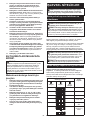
Makita DFT087F Benutzerhandbuch
- Kategorie
- Kraftschraubendreher
- Typ
- Benutzerhandbuch

DFT087F
DFT129F
EN Cordless Screwdriver INSTRUCTION MANUAL 4
FR Visseuse sans Fil MANUEL D’INSTRUCTIONS 11
DE Akku-Schrauber BETRIEBSANLEITUNG 19
IT Avvitatore a batteria ISTRUZIONI PER L’USO 28
NL Accuschroefmachine GEBRUIKSAANWIJZING 36
ES Atornillador Inalámbrico MANUAL DE
INSTRUCCIONES 44
PT Parafusadeira a Bateria MANUAL DE INSTRUÇÕES 52
DA Akku skruetrækker BRUGSANVISNING 60
EL 68
TR KULLANMA KILAVUZU 76

2
1
2
3
Fig.1
1
2
Fig.2
1
Fig.3
1
Fig.4
1
AB
Fig.5
1
Fig.6
1
Fig.7
1
2
Fig.8

3
1
23
Fig.9
Fig.10
12
Fig.11
132
Fig.12
1
2
2
Fig.13
Fig.14

4ENGLISH
ENGLISH (Original instructions)
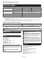
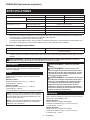
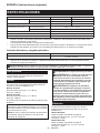
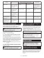
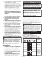
SPECIFICATIONS
Model: DFT087F DFT129F
Fastening torque Hard joint 3 - 8 N•m 5 - 12 N•m
Soft joint 3 - 8 N•m 5 - 12 N•m
No load speed (RPM) 100 - 1,250 min-1 70 - 900 min-1
Dimensions (L x W x H) with BL1815N battery 179 mm x 75 mm x 242 mm
with BL1860B battery 179 mm x 75 mm x 258 mm
Rated voltage D.C. 18 V
Net weight 1.3 - 1.6 kg
Applicable USB cable 661432-2
without notice.
-
est combinations, according to EPTA-Procedure 01/2014, are shown in the table.
Applicable battery cartridge and charger
Battery cartridge BL1815N / BL1820B / BL1830B / BL1840B / BL1850B / BL1860B
Charger DC18RC / DC18RD / DC18RE / DC18SD / DC18SE / DC18SF /
DC18SH / DC18WC
• Some of the battery cartridges and chargers listed above may not be available depending on your region of
residence.
WARNING: Only use the battery cartridges and chargers listed above. Use of any other battery cartridges
Intended use
The tool is intended for screw driving in wood, metal
and plastic.
Noise
The typical A-weighted noise level determined accord-
ing to EN62841-2-2:
Model DFT087F
Sound pressure level (LpA) : 71 dB(A)
Uncertainty (K) : 3 dB(A)
Model DFT129F
Sound pressure level (LpA) : 71 dB(A)
Uncertainty (K) : 3 dB(A)
The noise level under working may exceed 80 dB (A).
NOTE: The declared noise emission value(s) has
been measured in accordance with a standard test
method and may be used for comparing one tool with
another.
NOTE: The declared noise emission value(s)
may also be used in a preliminary assessment of
exposure.
WARNING: Wear ear protection.
WARNING: The noise emission during actual
value(s) depending on the ways in which the
tool is used especially what kind of workpiece is
processed.
WARNING: Be sure to identify safety mea-
sures to protect the operator that are based on an
estimation of exposure in the actual conditions of
use (taking account of all parts of the operating
cycle such as the times when the tool is switched
trigger time).
Vibration
The vibration total value (tri-axial vector sum) deter-
mined according to EN62841-2-2:
Model DFT087F
Work mode: screwdriving without impact
Vibration emission (ah) : 2.5 m/s2 or less
Uncertainty (K) : 1.5 m/s2
Model DFT129F
Work mode: screwdriving without impact
Vibration emission (ah) : 2.5 m/s2 or less
Uncertainty (K) : 1.5 m/s2

5ENGLISH
NOTE: The declared vibration total value(s) has been
measured in accordance with a standard test method
and may be used for comparing one tool with another.
NOTE: The declared vibration total value(s) may also
be used in a preliminary assessment of exposure.
WARNING: The vibration emission during
declared value(s) depending on the ways in which
the tool is used especially what kind of workpiece
is processed.
WARNING: Be sure to identify safety mea-
sures to protect the operator that are based on an
estimation of exposure in the actual conditions of
use (taking account of all parts of the operating
cycle such as the times when the tool is switched
trigger time).
EC Declaration of Conformity
For European countries only
The EC declaration of conformity is included as Annex A
to this instruction manual.
SAFETY WARNINGS
General power tool safety warnings
WARNING: Read all safety warnings, instruc-
with this power tool. Failure to follow all instructions
serious injury.
Save all warnings and instruc-
tions for future reference.
The term "power tool" in the warnings refers to your
mains-operated (corded) power tool or battery-operated
(cordless) power tool.
Cordless screwdriver safety
warnings
1. Hold the power tool by insulated gripping
surfaces, when performing an operation
where the fastener may contact hidden wiring.
Fasteners contacting a "live" wire may make
exposed metal parts of the power tool "live" and
could give the operator an electric shock.
2.
Be sure no one is below when using the tool in
high locations.
3.
4. Keep hands away from rotating parts.
5. Do not touch the bit or the workpiece immedi-
ately after operation; they may be extremely
hot and could burn your skin.
6. Always secure workpiece in a vise or similar
hold-down device.
7. Make sure there are no electrical cables, water
pipes, gas pipes etc. that could cause a hazard
if damaged by use of the tool.
SAVE THESE INSTRUCTIONS.
WARNING: DO NOT let comfort or familiarity
with product (gained from repeated use) replace
strict adherence to safety rules for the subject
product.
MISUSE or failure to follow the safety rules stated
in this instruction manual may cause serious
personal injury.
Important safety instructions for
battery cartridge
1.
Before using battery cartridge, read all instruc-
tions and cautionary markings on (1) battery
charger, (2) battery, and (3) product using battery.
2. Do not disassemble or tamper with the battery
cartridge.
or explosion.
3. If operating time has become excessively
shorter, stop operating immediately. It may
result in a risk of overheating, possible burns
and even an explosion.
4.
If electrolyte gets into your eyes, rinse them out
with clear water and seek medical attention right
away. It may result in loss of your eyesight.
5. Do not short the battery cartridge:
(1) Do not touch the terminals with any con-
ductive material.
(2) Avoid storing battery cartridge in a con-
tainer with other metal objects such as
nails, coins, etc.
(3) Do not expose battery cartridge to water
or rain.
A battery short can cause a large current
breakdown.
6. Do not store and use the tool and battery car-
tridge in locations where the temperature may
reach or exceed 50 °C (122 °F).
7. Do not incinerate the battery cartridge even if
it is severely damaged or is completely worn
8. Do not nail, cut, crush, throw, drop the battery
cartridge, or hit against a hard object to the
battery cartridge. Such conduct may result in a
9. Do not use a damaged battery.
10.
The contained lithium-ion batteries are subject to
the Dangerous Goods Legislation requirements.
For commercial transports e.g. by third parties,
forwarding agents, special requirement on pack-
aging and labeling must be observed.
For preparation of the item being shipped, consult-
ing an expert for hazardous material is required.
Please also observe possibly more detailed
national regulations.
battery in such a manner that it cannot move
around in the packaging.

6ENGLISH
11. When disposing the battery cartridge, remove
it from the tool and dispose of it in a safe
place. Follow your local regulations relating to
disposal of battery.
12. Use the batteries only with the products
Installing the batteries to
-
sive heat, explosion, or leak of electrolyte.
13. If the tool is not used for a long period of time,
the battery must be removed from the tool.
14. During and after use, the battery cartridge may
take on heat which can cause burns or low
temperature burns. Pay attention to the han-
dling of hot battery cartridges.
15. Do not touch the terminal of the tool imme-
diately after use as it may get hot enough to
cause burns.
16. Do not allow chips, dust, or soil stuck into the
terminals, holes, and grooves of the battery
cartridge.
burst and malfunction of the tool or battery car-
tridge, resulting in burns or personal injury.
17. Unless the tool supports the use near
high-voltage electrical power lines, do not use
the battery cartridge near high-voltage electri-
cal power lines. It may result in a malfunction or
breakdown of the tool or battery cartridge.
18. Keep the battery away from children.
SAVE THESE INSTRUCTIONS.
CAUTION: Only use genuine Makita batteries.
Use of non-genuine Makita batteries, or batteries that
have been altered, may result in the battery bursting
also void the Makita warranty for the Makita tool and
charger.
Tips for maintaining maximum
battery life
1. Charge the battery cartridge before completely
discharged. Always stop tool operation and
charge the battery cartridge when you notice
less tool power.
2. Never recharge a fully charged battery car-
tridge. Overcharging shortens the battery
service life.
3. Charge the battery cartridge with room tem-
perature at 10 °C - 40 °C (50 °F - 104 °F). Let
a hot battery cartridge cool down before
charging it.
4. When not using the battery cartridge, remove
it from the tool or the charger.
5. Charge the battery cartridge if you do not use
it for a long period (more than six months).
FUNCTIONAL DESCRIPTION
CAUTION: Always be sure that the tool is
before adjusting or checking function on the tool.
Installing or removing battery cartridge
CAUTION:
installing or removing of the battery cartridge.
CAUTION: Hold the tool and the battery car-
cartridge. Failure to hold the tool and the battery
and result in damage to the tool and battery cartridge
and a personal injury.
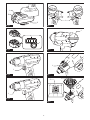
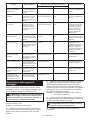
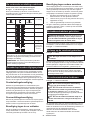
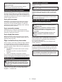
Fig.1: 1. Red indicator 2. Button 3. Battery cartridge
To remove the battery cartridge, slide it from the tool
while sliding the button on the front of the cartridge.
To install the battery cartridge, align the tongue on the
battery cartridge with the groove in the housing and slip
it into place. Insert it all the way until it locks in place
with a little click. If you can see the red indicator as
CAUTION: Always install the battery cartridge
fully until the red indicator cannot be seen. If not,
it may accidentally fall out of the tool, causing injury to
you or someone around you.
CAUTION: Do not install the battery cartridge
forcibly. If the cartridge does not slide in easily, it is
not being inserted correctly.
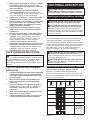
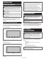
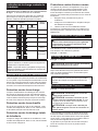
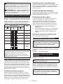
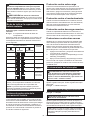
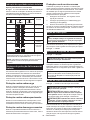
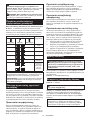
Indicating the remaining battery capacity
Only for battery cartridges with the indicator
Fig.2: 1. Indicator lamps 2. Check button
Press the check button on the battery cartridge to indi-
cate the remaining battery capacity. The indicator lamps
light up for a few seconds.
Indicator lamps Remaining
capacity
Lighted Blinking
75% to 100%
50% to 75%
25% to 50%
0% to 25%
Charge the
battery.
The battery
may have
malfunctioned.

7ENGLISH
NOTE: Depending on the conditions of use and the
from the actual capacity.
NOTE:
the battery protection system works.
Tool / battery protection system
The tool is equipped with a tool/battery protection sys-
motor to extend tool and battery life. The tool will auto-
matically stop during operation if the tool or battery is
placed under one of the following conditions:
Overload protection
When the tool/battery is operated in a manner that
causes it to draw an abnormally high current, the tool
and stop the application that caused the tool to become
overloaded. Then turn the tool on to restart.
Overheat protection
When the tool/battery is overheated, the tool stops
automatically. In this situation, let the tool/battery cool
before turning the tool on again.
Overdischarge protection
When the battery capacity is not enough, the tool stops
automatically. In this case, remove the battery from the
tool and charge the battery.
Protections against other causes
Protection system is also designed for other causes
that could damage the tool and allows the tool to stop
automatically. Take all the following steps to clear the
causes, when the tool has been brought to a temporary
halt or stop in operation.
restart.
2. Charge the battery(ies) or replace it/them with
recharged battery(ies).
3. Let the tool and battery(ies) cool down.
If no improvement can be found by restoring protection
system, then contact your local Makita Service Center.
Switch action
WARNING: Before installing the battery car-
tridge into the tool, always check to see that the
switch trigger actuates properly and returns to
the "OFF" position when released.
To start the tool, simply pull the switch trigger. Release
the switch trigger to stop.
Fig.3: 1. Switch trigger
Lighting up the front lamp
Fig.4: 1. Lamp
CAUTION: Do not look in the light or see the
source of light directly.
Pull the switch trigger to light up the lamp. The lamp
keeps on lighting while the switch trigger is being pulled.
The lamp goes out approximately 10 seconds after
releasing the switch trigger.
NOTE:
the lamp. Be careful not to scratch the lens of lamp, or
it may lower the illumination.
Reversing switch action
Fig.5: 1. Reversing switch lever
CAUTION: Always check the direction of
rotation before operation.
CAUTION: Use the reversing switch only after
the tool comes to a complete stop. Changing the
direction of rotation before the tool stops may dam-
age the tool.
CAUTION: When not operating the tool,
always set the reversing switch lever to the neu-
tral position.
This tool has a reversing switch to change the direction
of rotation. Depress the reversing switch lever from the
A side for clockwise rotation or from the B side for coun-
terclockwise rotation.
When the reversing switch lever is in the neutral posi-
tion, the switch trigger cannot be pulled.
Electric brake
This tool is equipped with an electric brake. If the tool
consistently fails to quickly stop after the switch trigger
is released, have the tool serviced at a Makita service
center.
NOTE: An electric brake function can be activated or
deactivated in application preferences. For detailed
information, refer to the instruction manual supplied
with the application software designed for this tool.

8ENGLISH
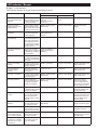
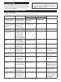
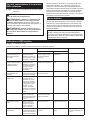
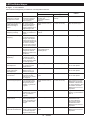
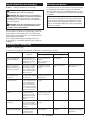
LED indicator / Beeper
Fig.6: 1. LED indicator
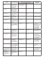
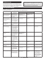
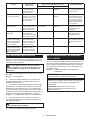
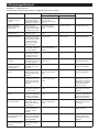
LED indicator / Beeper on the tool shows the following functions.
Function Status of the tool Status of the LED indicator/beeper Action to be taken
LED indicator Beeper
Check of the LED indi-
cator, lamp and beeper
operation
When the battery car-
tridge is installed, the tool
checks for its LED indica-
tor, lamp and beeper.
next red.
(And then the lamp
comes on.)
A series of very short
beeps
–
Detection of switch
trigger operation when
installing battery
When the battery cartridge
is installed with the switch
trigger pulled, the tool stops
to avoid unintentional start.
Blinks in red and green
alternatively.
A series of short beeps Release the switch
trigger.
Auto-stop with fastening
completion
The tool setting has
been achieved and the
tool has stopped.
Lights up in green for
approximately one
second.
– –
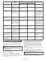
-
cient fastening
The tool has not completed
the tool setting because the
switch trigger has released
before reaching the set val-
ues. Otherwise, the settings
of "Failure Criteria for Phase"
has been achieved.
Lights up in red. A long beep Retighten the screw.
Intermission between
the phases
The tool is in the inter-
by the setting of "Shift to
the next Phase".
Lights up or blinks in
green (depending on
settings)
– –
Double-hitting detection
When the operator starts
to re-fasten an already-fas-
tened screw, the tool detect
it and stops.
Lights up in red. A long beep –
Alarm for low battery
capacity
The battery power became
low and it is time to replace
the battery cartridge.
Blinks in red slowly. A series of long beeps Replace the battery with
fully charged one.
Auto-stop with low
remaining battery
capacity
The battery power is
almost used up and the
tool stopped.
Lights up in red. A long beep Replace the battery with
fully charged one.
Anti-reset of controller
The battery voltage dropped
abnormally for some reason,
and the tool stopped.
Blinks in red and green
alternatively.
A series of short beeps Replace the battery with
fully charged one.
Overload protection An abnormally high
through the controller
and the tool stopped.
Blinks in red and green
alternatively.
A series of short beeps
Remove the cause of
overload and restart the
tool. If no improvement is
found, ask your local Makita
Service Center for repair.
Overheat protection The motor or the control-
ler heated up abnormally
and the tool stopped.
Blinks in red quickly. A series of short beeps Remove the battery car-
tridge immediately and
cool the tool down.
Failure to detect heat
of motor
The detection unit of
the motor fails to detect
the heat because the
cord has broken or other
reasons.
Blinks in red quickly. A series of short beeps
Remove the battery cartridge
and cool the tool down. If the
indicator does not stop, ask
your local Makita Service
Center for repair.
Motor or controller failure
detection
Motor or controller failure
has been detected. At this
time, tool does not work.
Blinks in red and green
alternatively.
A series of short beeps Ask your local Makita
Service Center for repair.
Maintenance alarm
A maintenance time has
come according to your pre-
set number of screws driven.
Blinks in yellow. –Reset the alarm with the
application software.
Alarm for unavailable data
communication (with the
tool in connection with PC)
Data cannot be exchanged
between the tool and PC in
spite of the connection.
Blinks in yellow. –Restart the application
software and re-connect
the USB cable.
Indication that data com-
munication is available
(with the tool in connec-
tion with PC)
The tool is connected to
PC and data communi-
cation is available.
Blinks in green. – –

9ENGLISH
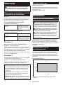
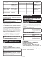
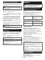
Adjusting the fastening torque
When you wish to drive machine screws, hex bolts,
etc. with the predetermined torque, adjust the fastening
torque as follows.
CAUTION: When adjusting the fastening
torque, remove the battery cartridge (excluding
the process of working with the battery cartridge
attached).
1. Open the change plate by hand so that you can
see a hole.
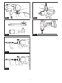
Fig.7: 1. Change plate
2. Pull the switch trigger and release it so that the
adjust ring rotates and the hole becomes visible. And
then remove the battery cartridge.
3. Use an optional adjust grip to adjust the fastening
torque. Insert the pin of the adjust grip into the hole
in the front of the tool. And then, turn the adjust grip
clockwise to set a greater fastening torque, and coun-
terclockwise to set a smaller fastening torque.
Fig.8: 1. Adjust grip 2. Hole for adjust grip
4. Insert the battery cartridge and be sure that a
fastening torque has been set up by using a fastening
torque tester.
CAUTION: Remove the adjust grip before
turning on the power of the tool.
5. Close the change plate by hand securely.
Adjusting no-load speed and
revolution angle etc.
You can adjust the no-load speed, number of turn, etc.
of the tool with your computer. Install the application
software in your computer and connect it to the tool with
an USB cable.
Fig.9: 1. USB port 2. USB cover 3. USB cable
NOTICE: Make sure that the USB cover closed
when fastening.
NOTE: Use the Makita genuine USB cable to con-
nect your computer to the tool. Refer to the section
"SPECIFICATIONS".
NOTE: For the application software, please contact
Makita sales representative.
ASSEMBLY
CAUTION: Always be sure that the tool is
before carrying out any work on the tool.
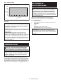
Installing or removing driver bit/socket bit
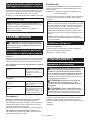
Fig.10
Use only driver bit/socket bit that has inserting portion
socket bit.
For tool with shallow driver bit hole
A=12mm
B=9mm
Use only these type of driver
bit. Follow the procedure
1. (Note) Bit-piece is not
necessary.
For tool with deep driver bit hole
A=17mm
B=14mm
To install these types of driver
bits, follow the procedure 1.
A=12mm
B=9mm
To install these types of driver
bits, follow the procedure 2.
(Note) Bit-piece is necessary
for installing the bit.
Procedure 1
For tool without one-touch type sleeve
Fig.11: 1. Driver bit 2. Sleeve
To install the driver bit, pull the sleeve in the direction of the
arrow and insert the driver bit into the sleeve as far as it will go.
Then release the sleeve to secure the driver bit.
For tool with one-touch type sleeve
To install the driver bit, insert the driver bit into the
sleeve as far as it will go.
Procedure 2
In addition to Procedure 1, insert the bit-piece into the
sleeve with its pointed end facing in.
Fig.12: 1. Driver bit 2. Bit-piece 3. Sleeve
To remove the driver bit, pull the sleeve in the direction
of the arrow and pull the driver bit out.
NOTE: If the driver bit is not inserted deep enough
into the sleeve, the sleeve will not return to its original
position and the driver bit will not be secured. In this
case, try re-inserting the bit according to the instruc-
tions above.
NOTE:
the sleeve and insert it into the sleeve as far as it will
go.
NOTE: After inserting the driver bit, make sure that it
Installing hook
Optional accessory
The hook is useful to hang the tool. Install the hook to
the holes on the tool body.
Fig.13: 1. Hook 2. Hole

10 ENGLISH
OPERATION
Screwdriving operation
CAUTION:
driver bit/socket bit securely over the screw head/bolt
head during fastening operation. Failure to do so may
cause mishandling of the tool resulting in personal injury.
CAUTION: Make sure that the bit is inserted
straight in the screw head, or the screw and/or bit
may be damaged.
CAUTION: Keep hands away from the rotating
parts during operation. Failure to do so may cause
your hands to be caught in the moving parts, resulting
in personal injury.
Place the point of the driver bit in the screw head and
apply pressure to the tool. Then switch the tool on.
When the clutch cuts in, the motor will stop automati-
cally. Then release the switch trigger.
Fig.14
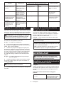
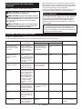
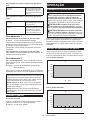
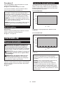
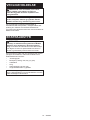
Limits of fastening capacity
Use the tool within the limits of fastening capacity. If you
use the tool beyond the limits, the clutch does not work.
And the tool cannot deliver enough fastening torque.
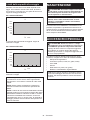
For model DFT087F
38
4567
360°
300°
240°
180°
120°
60°
30°
1
3
2
N•m
1. Range of fastening capacity 2. Rotation angle
3. Torque
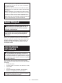
For model DFT129F
5867 9101112
360°
300°
240°
180°
120°
60°
30°
1
3
2
N•m
1. Range of fastening capacity 2. Rotation angle
3. Torque
NOTE: The rotation angle is the angle from the point
that the bolt is tightened in 50% of desired torque to
the point that the bolt is tightened in 100% torque.
NOTE: This reference value is measured by the mea-
NOTE: Use of a cold battery cartridge may give
warning for battery capacity by LED indicator and
beeper and stop the tool immediately, even if it is fully
charged. In this case, the fastening capacity may be
MAINTENANCE
CAUTION: Always be sure that the tool is
before attempting to perform inspection or
maintenance.
NOTICE: Never use gasoline, benzine, thinner,
alcohol or the like. Discoloration, deformation or
cracks may result.
To maintain product SAFETY and RELIABILITY,
repairs, any other maintenance or adjustment should
be performed by Makita Authorized or Factory Service
Centers, always using Makita replacement parts.
OPTIONAL
ACCESSORIES
CAUTION: These accessories or attachments
are recommended for use with your Makita tool
The use of any other
accessories or attachments might present a risk of
injury to persons. Only use accessory or attachment
for its stated purpose.
If you need any assistance for more details regard-
ing these accessories, ask your local Makita Service
Center.
• Adjust grip
• Protector (Natural, Red, Blue, Yellow, Green)
• USB cable
• Hook
• Lock nut (Red, Blue, Yellow)
• Makita genuine battery and charger
NOTE: Some items in the list may be included in the
tool package as standard accessories. They may

11 FRANÇAIS
FRANÇAIS (Instructions originales)
SPÉCIFICATIONS
Modèle : DFT087F DFT129F
Couple de serrage Joint rigide 3 - 8 N•m 5 - 12 N•m
Joint souple 3 - 8 N•m 5 - 12 N•m
Vitesse à vide (tr/min) 100 - 1 250 min-1 70 - 900 min-1
Dimensions (L x l x H) batterie BL1815N incluse 179 mm x 75 mm x 242 mm
batterie BL1860B incluse 179 mm x 75 mm x 258 mm
Tension nominale 18 V CC
Poids net 1,3 - 1,6 kg
Câble USB applicable 661432-2
plus lourde, conformément à la procédure EPTA 01/2014, sont indiquées dans le tableau.
Batterie et chargeur applicables
Batterie BL1815N / BL1820B / BL1830B / BL1840B / BL1850B / BL1860B
Chargeur DC18RC / DC18RD / DC18RE / DC18SD / DC18SE / DC18SF /
DC18SH / DC18WC
• Certains chargeurs et batteries répertoriés ci-dessus peuvent ne pas être disponibles selon la région où vous
résidez.
AVERTISSEMENT : N’utilisez que les batteries et les chargeurs répertoriés ci-dessus. L’utilisation
d’autres batteries et chargeurs peut provoquer des blessures et/ou un incendie.
Utilisations
L’outil est conçu pour serrer des vis dans le bois, le
métal et le plastique.
Bruit
Niveau de bruit pondéré A typique, déterminé selon
EN62841-2-2 :
Modèle DFT087F
Niveau de pression sonore (LpA) : 71 dB (A)
Incertitude (K) : 3 dB (A)
Modèle DFT129F
Niveau de pression sonore (LpA) : 71 dB (A)
Incertitude (K) : 3 dB (A)
Le niveau de bruit en fonctionnement peut dépasser 80 dB (A).
NOTE : La ou les valeurs d’émission de bruit décla-
rées ont été mesurées conformément à la méthode
de test standard et peuvent être utilisées pour com-
parer les outils entre eux.
NOTE : La ou les valeurs d’émission de bruit décla-
rées peuvent aussi être utilisées pour l’évaluation
préliminaire de l’exposition.
AVERTISSEMENT : Portez un serre-tête
antibruit.
AVERTISSEMENT : L’émission de bruit
lors de l’usage réel de l’outil électrique peut être
la façon dont l’outil est utilisé, particulièrement
selon le type de pièce usinée.
AVERTISSEMENT : Les mesures de sécurité
à prendre pour protéger l’utilisateur doivent être
basées sur une estimation de l’exposition dans
des conditions réelles d’utilisation (en tenant
compte de toutes les composantes du cycle
d’utilisation, comme par exemple le moment de
sa mise hors tension, lorsqu’il tourne à vide et le
moment de son déclenchement).
Vibrations
Valeur totale de vibrations (somme de vecteur triaxial)
déterminée selon EN62841-2-2 :
Modèle DFT087F
Mode de travail : vissage sans impact
Émission de vibrations (ah) : 2,5 m/s2 ou moins
Incertitude (K) : 1,5 m/s2
Modèle DFT129F
Mode de travail : vissage sans impact
Émission de vibrations (ah) : 2,5 m/s2 ou moins
Incertitude (K) : 1,5 m/s2

12 FRANÇAIS
NOTE : La ou les valeurs de vibration totales décla-
rées ont été mesurées conformément à la méthode
de test standard et peuvent être utilisées pour com-
parer les outils entre eux.
NOTE : La ou les valeurs de vibration totales décla-
rées peuvent aussi être utilisées pour l’évaluation
préliminaire de l’exposition.
AVERTISSEMENT : L’émission de vibrations
lors de l’usage réel de l’outil électrique peut être
la façon dont l’outil est utilisé, particulièrement
selon le type de pièce usinée.
AVERTISSEMENT : Les mesures de sécurité
à prendre pour protéger l’utilisateur doivent être
basées sur une estimation de l’exposition dans
des conditions réelles d’utilisation (en tenant
compte de toutes les composantes du cycle
d’utilisation, comme par exemple le moment de
sa mise hors tension, lorsqu’il tourne à vide et le
moment de son déclenchement).
Déclaration de conformité CE
Pour les pays européens uniquement
La déclaration de conformité CE est fournie en Annexe
A à ce mode d’emploi.
CONSIGNES DE SÉCURITÉ
Consignes de sécurité générales
pour outils électriques
AVERTISSEMENT : Veuillez lire les
consignes de sécurité, instructions, illustrations
électrique. Le non-respect de toutes les instructions
indiquées ci-dessous peut entraîner une électrocu-
tion, un incendie et/ou de graves blessures.
Conservez toutes les mises en
garde et instructions pour réfé-
rence ultérieure.
Le terme « outil électrique » dans les avertissements
fait référence à l’outil électrique alimenté par le secteur
(avec cordon d’alimentation) ou à l’outil électrique fonc-
tionnant sur batterie (sans cordon d’alimentation).
Consignes de sécurité pour
1. Tenez l’outil électrique par des surfaces de
sous tension peut transmettre du courant dans les
et électrocuter l’opérateur.
2. Assurez-vous toujours d’avoir une bonne
assise.
Veillez à ce que personne ne se trouve en
dessous de vous quand vous utilisez l’outil en
hauteur.
3. Tenez l’outil fermement.
4. Gardez vos mains à l’écart des pièces en
rotation.
5. Ne touchez pas l’embout ou la pièce immé-
diatement après l’exécution du travail ; ils
peuvent être extrêmement chauds et vous
brûler la peau.
6. Immobilisez toujours la pièce dans un étau ou
un dispositif de retenue similaire.
7. -
triques, de conduites d’eau, de conduites
de gaz, etc., présentant un risque s’ils sont
endommagés suite à l’utilisation de l’outil.
CONSERVEZ CES
INSTRUCTIONS.
AVERTISSEMENT : NE vous laissez PAS
sentiment d’aisance et de familiarité avec le
produit, en négligeant le respect rigoureux des
consignes de sécurité qui accompagnent le pro-
duit en question.
La MAUVAISE UTILISATION de l’outil ou l’igno-
rance des consignes de sécurité indiquées
dans ce mode d’emploi peut entraîner de graves
blessures.
Consignes de sécurité importantes
pour la batterie
1. Avant d’utiliser la batterie, lisez toutes les
instructions et précautions relatives (1) au
chargeur de batterie, (2) à la batterie, et (3) au
produit utilisant la batterie.
2.
batterie. Cela pourrait entraîner un incendie, une
chaleur excessive ou une explosion.
3. Cessez immédiatement l’utilisation si le temps
de fonctionnement devient excessivement
voire d’explosion.
4. Si l’électrolyte pénètre dans vos yeux, rin-
cez-les à l’eau claire et consultez immédiate-
ment un médecin. Il y a risque de perte de la
vue.
5. Ne court-circuitez pas la batterie :
(1) Ne touchez les bornes avec aucun maté-
riau conducteur.
(2) Évitez de ranger la batterie dans un
conteneur avec d’autres objets métal-
liques, par exemple des clous, des pièces
de monnaie, etc.
(3) N’exposez pas la batterie à l’eau ou à la
pluie.
Un court-circuit de la batterie peut provoquer
une intensité de courant élevée, une sur-
panne.

13 FRANÇAIS
6. Ne rangez ni n’utilisez l’outil et la batterie dans
un endroit où la température risque d’atteindre
ou de dépasser 50 °C.
7.
Ne jetez pas la batterie au feu même si elle est
sérieusement endommagée ou complètement épui-
sée. La batterie peut exploser au contact du feu.
8. Abstenez-vous de clouer, couper, écraser,
jeter, laisser tomber la batterie, ou de la heur-
ter contre un objet dur. Cela pourrait entraîner
un incendie, une chaleur excessive ou une
explosion.
9. N’utilisez pas la batterie si elle est
endommagée.
10. Les batteries au lithium-ion contenues sont
soumises aux exigences de la législation sur
les marchandises dangereuses.
Lors du transport commercial par des tierces
parties ou des transitaires par exemple, des exi-
d’emballage doivent être respectées.
Pour la préparation de l’article expédié, il est
nécessaire de consulter un expert en matériau
dangereux. Veuillez également respecter les
réglementations nationales susceptibles d’être
plus détaillées.
Recouvrez les contacts exposés avec du ruban
adhésif ou du ruban de masquage et emballez la
batterie de telle sorte qu’elle ne puisse pas bouger
dans l’emballage.
11. Lors de la mise au rebut de la batterie, reti-
rez-la de l’outil et jetez-la en lieu sûr. Suivez les
réglementations locales en matière de mise au
rebut des batteries.
12. Utilisez les batteries uniquement avec les
L’insertion de
batteries dans des produits non conformes peut
provoquer un incendie, une chaleur excessive,
une explosion ou une fuite de l’électrolyte.
13. Lorsque vous n’utilisez pas l’outil pendant une
période prolongée, la batterie doit être retirée
de l’outil.
14. Pendant et après l’utilisation, la batterie peut
compris en cas de température relativement
basse. Manipulez les batteries chaudes avec
précaution.
15. Ne touchez pas la borne de l’outil immédiate-
ment après utilisation car elle peut être assez
chaude pour provoquer des brûlures.
16. Évitez que des copeaux, de la poussière ou
du sol adhèrent aux bornes, aux trous et aux
rainures de la batterie. Cela peut provoquer un
dysfonctionnement de l’outil ou de la batterie, ce
qui peut entraîner des brûlures ou des blessures.
17. À moins que l’outil prenne en charge un tel
usage, n’utilisez pas la batterie à proximité de
lignes électriques haute tension. Cela pourrait
entraîner un dysfonctionnement ou casser l’outil
ou la batterie.
18. Conservez la batterie hors de portée des
enfants.
CONSERVEZ CES
INSTRUCTIONS.
ATTENTION :
N’utilisez que des batteries Makita
d’origine. L’utilisation de batteries de marque autre que
des batteries, ce qui présente un risque d’incendie, de dom-
mages matériels et corporels. Cela annulera également la
garantie Makita pour l’outil et le chargeur Makita.
Conseils pour assurer la durée
de vie optimale de la batterie
1. Chargez la batterie avant qu’elle ne soit com-
plètement déchargée. Arrêtez toujours l’outil
et rechargez la batterie quand vous remarquez
que la puissance de l’outil diminue.
2.
Ne rechargez jamais une batterie complètement chargée.
La surcharge réduit la durée de service de la batterie.
3.
Chargez la batterie à une température ambiante
comprise entre 10 °C et 40 °C. Avant de charger
une batterie chaude, laissez-la refroidir.
4. Lorsque vous n’utilisez pas la batterie, reti-
rez-la de l’outil ou du chargeur.
5.
Rechargez la batterie si elle est restée inutilisée
pendant une période prolongée (plus de six mois).
DESCRIPTION DU
FONCTIONNEMENT
ATTENTION : Assurez-vous toujours que
l’outil est hors tension et que sa batterie est
fonctionnement.
Insertion ou retrait de la batterie
ATTENTION : Éteignez toujours l’outil avant
de mettre en place ou de retirer la batterie.
ATTENTION : Tenez fermement l’outil et la
batterie lors de la mise en place ou du retrait de
la batterie. Si vous ne tenez pas fermement l’outil
et la batterie, ils peuvent vous glisser des mains, et
s’abîmer ou vous blesser.
Fig.1: 1. Indicateur rouge 2. Bouton 3. Batterie
Pour retirer la batterie, faites-la glisser hors de l’outil
tout en faisant glisser le bouton à l’avant de la batterie.
Pour mettre la batterie en place, alignez la languette de la batterie
avec la rainure du compartiment puis insérez la batterie. Insérez-la
est bien en place. Si vous pouvez voir l’indicateur rouge comme
ATTENTION : Insérez toujours complètement
la batterie jusqu’à ce que l’indicateur rouge ne
soit plus visible. Sinon, elle pourrait tomber acciden-
tellement de l’outil, au risque de vous blesser ou de
ATTENTION : N’insérez pas la batterie de
force. Si elle ne glisse pas facilement, c’est que vous
ne l’insérez pas correctement.

14 FRANÇAIS
Indication de la charge restante de
la batterie
Uniquement pour les batteries avec voyant lumineux
Fig.2: 1. Témoins 2.
pour indiquer la charge restante de la batterie. Les
témoins s’allument pendant quelques secondes.
Témoins Charge
restante
Allumé Éteint Clignotant
75 % à 100 %
50 % à 75 %
25 % à 50 %
0 % à 25 %
Chargez la
batterie.
Anomalie
possible
de la batterie.
NOTE : Selon les conditions d’utilisation et la tem-
NOTE :
protection de la batterie.
Système de protection de l’outil/la batterie
-
moteur pour prolonger la durée de vie de l’outil et de la batte-
rie. Si l’outil ou la batterie se trouve dans l’une des situations
suivantes, l’outil cessera automatiquement de fonctionner.
Protection contre la surcharge
provoquant un appel de courant anormalement élevé,
l’outil s’arrête automatiquement. Dans ce cas, éteignez
l’outil et arrêtez la tâche ayant provoqué la surcharge
de l’outil. Puis rallumez l’outil pour reprendre la tâche.
s’arrête automatiquement. Dans ce cas, laissez l’outil
ou la batterie refroidir avant de rallumer l’outil.
Protection contre la décharge totale
de la batterie
s’arrête automatiquement. Dans ce cas, retirez la batte-
rie de l’outil et chargez-la.
Protections contre d’autres causes
d’autres causes qui pourraient endommager l’outil
et lui permet de s’arrêter automatiquement. Suivez
toutes les étapes ci-dessous pour éliminer les causes,
lorsque l’outil a été arrêté provisoirement ou a cessé de
fonctionner.
1. Éteignez l’outil, puis rallumez-le pour le
redémarrer.
2. Chargez la ou les batteries ou remplacez-les par
des batteries rechargées.
3. Laissez l’outil et la ou les batteries refroidir.
-
Makita local.
AVERTISSEMENT : Avant d’insérer la batte-
fonctionne bien et revient en position d’arrêt
Pour arrêter l’outil, relâchez la gâchette.
Fig.3: 1. Gâchette
Allumage de la lampe avant
Fig.4: 1. Lampe
ATTENTION : Évitez de regarder directement
le faisceau lumineux ou sa source.
Enclenchez la gâchette pour allumer la lampe. La
lampe reste allumée tant que la gâchette est enclen-
avoir relâché la gâchette.
NOTE : Retirez la saleté sur la lentille de la lampe
la lentille de la lampe sous peine de diminuer son
éclairage.
Fonctionnement de l’inverseur
Fig.5: 1. Levier de l’inverseur
ATTENTION :
rotation avant d’utiliser l’outil.
ATTENTION : N’utilisez l’inverseur qu’une
fois que l’outil est complètement arrêté. Si vous
changez le sens de rotation avant l’arrêt de l’outil,
vous risquez de l’endommager.
ATTENTION : Lorsque vous n’utilisez pas
l’outil, placez toujours le levier de l’inverseur en
position neutre.
le sens de rotation. Enfoncez le levier de l’inverseur
du côté A pour une rotation dans le sens des aiguilles
d’une montre, ou du côté B pour une rotation dans le
sens inverse des aiguilles d’une montre.
La gâchette ne peut pas être enclenchée lorsque le
levier de l’inverseur se trouve en position neutre.

15 FRANÇAIS
Frein électrique
Cet outil est équipé d’un frein électrique. Si systémati-
le relâchement de la gâchette, faites réparer l’outil dans
un centre de service Makita.
NOTE : Une fonction de frein électrique peut être acti-
vée ou désactivée dans les préférences de l’applica-
tion. Pour des informations détaillées, reportez-vous
au manuel d’instructions accompagnant le logiciel
d’application conçu pour cet outil.
Témoin DEL/avertisseur sonore
Fig.6: 1. Témoin DEL
Le témoin DEL/l’avertisseur sonore sur l’outil indique les fonctions suivantes.
Fonction État de l’outil État du témoin DEL/de l’avertisseur sonore Mesure à prendre
Témoin DEL Avertisseur sonore
-
nement du témoin DEL,
de la lampe et de l’aver-
tisseur sonore
Lorsque la batterie est
témoin DEL, la lampe et
l’avertisseur sonore.
S’allume d’abord en vert,
puis en rouge.
(Ensuite la lampe
s’allume.)
signaux sonores
-
Détection du fonctionne-
ment de la gâchette lors
de la mise en place de la
batterie
Lorsque la batterie est
insérée avec la gâchette
enclenchée, l’outil
s’arrête pour éviter un
démarrage intempestif.
Clignote alternativement
en rouge et en vert.
Série de courts signaux
sonores
Relâchez la gâchette.
Arrêt automatique à la
Le réglage de l’outil a été
obtenu et l’outil s’est arrêté.
S’allume en vert pendant
environ une seconde.
- -
Alarme en cas de ser-
le réglage de l’outil, car
la gâchette a été relâ-
chée avant d’atteindre
Autrement, les réglages
phase » ont été obtenus.
S’allume en rouge. Long signal sonore Resserrez la vis.
Interruption entre les
phases
L’outil est dans la
période d’interruption
de « Phase suivante ».
S’allume ou clignote en
vert (selon les réglages).
- -
Détection de double
frappe
Lorsque l’utilisateur se
met à reserrer une vis
déjà serrée, l’outil le
détecte et s’arrête.
S’allume en rouge. Long signal sonore -
Alarme en cas de faible
charge de la batterie
La puissance de la
batterie diminue et le
moment est venu de
changer la batterie.
Clignote lentement en
rouge.
Série de longs signaux
sonores
Remplacez la batterie
-
ment chargée.
Arrêt automatique en
cas de faible charge
restante de la batterie
La batterie est presque
et l’outil s’est arrêté.
S’allume en rouge. Long signal sonore Remplacez la batterie
-
ment chargée.
Anti-réinitialisation du
contrôleur
Une baisse anormale
de tension est survenue
sur la batterie pour une
raison quelconque et
l’outil s’est arrêté.
Clignote alternativement
en rouge et en vert.
Série de courts signaux
sonores
Remplacez la batterie
-
ment chargée.
Protection contre la
surcharge
Un courant anormale-
ment élevé continuait de
circuler dans le contrô-
leur et l’outil s’est arrêté.
Clignote alternativement
en rouge et en vert.
Série de courts signaux
sonores
Éliminez la cause de la
surcharge et redémarrez
l’outil. En l’absence
réparation à votre centre
de service Makita local.
Protection contre la
Le moteur ou le contrô-
leur ont présenté une
l’outil s’est arrêté.
Clignote rapidement en
rouge.
Série de courts signaux
sonores
Retirez immédiatement
la batterie et laissez
refroidir l’outil.
Incapacité à détecter la
L’unité de détection du
moteur n’a pas pu détec-
cordon est rompu ou
pour toute autre raison.
Clignote rapidement en
rouge.
Série de courts signaux
sonores
Retirez la batterie et lais-
sez refroidir l’outil. Si le
voyant ne s’arrête pas,
sollicitez une réparation
service Makita.

16 FRANÇAIS
Fonction État de l’outil État du témoin DEL/de l’avertisseur sonore Mesure à prendre
Témoin DEL Avertisseur sonore
Détection de défail-
lance du moteur ou du
contrôleur
Une défaillance du
moteur ou du contrôleur
a été détectée. À ce
moment précis, l’outil ne
fonctionne pas.
Clignote alternativement
en rouge et en vert.
Série de courts signaux
sonores
votre centre de service
local.
Alarme pour l’entretien Le moment est venu de
procéder à l’entretien
-
Clignote en jaune. -Réinitialisez l’alarme
avec le logiciel
d’application.
Alarme en cas de com-
munication de données
non disponible (avec
l’outil connecté à un
ordinateur)
Les données ne
peuvent pas être
échangées entre l’outil
et l’ordinateur malgré la
connexion.
Clignote en jaune. -Redémarrez le logiciel
d’application et rebran-
chez le câble USB.
Indication que la com-
munication de données
est disponible (avec
l’outil connecté à un
ordinateur)
L’outil est connecté à
l’ordinateur et la commu-
nication des données est
disponible.
Clignote en vert. - -
Réglage du couple de serrage
Pour serrer des vis mécaniques, des boulons à six pans
creux, etc., avec un couple de serrage donné, procédez
au réglage du couple de serrage de la façon suivante.
ATTENTION : Lors du réglage du couple de
serrage, retirez la batterie (sauf dans le cas de
1. Ouvrez manuellement la plaque de changement
de sorte que vous puissiez voir un trou.
Fig.7: 1. Plaque de changement
2. Enclenchez la gâchette et relâchez-la de sorte
que la bague de réglage pivote et que le trou devienne
visible. Puis, retirez la batterie.
3. Utilisez une poignée de réglage en option pour
procéder au réglage du couple de serrage. Insérez la
broche de la poignée de réglage dans le trou à l’avant
de l’outil. Tournez ensuite la poignée de réglage dans
le sens des aiguilles d’une montre pour augmenter
le couple de serrage, et dans le sens inverse pour le
réduire.
Fig.8: 1. Poignée de réglage 2. Trou pour la poi-
gnée de réglage
4. Insérez la batterie et assurez-vous que le couple
de serrage est bien réglé, au moyen d’un testeur de
couple de serrage.
ATTENTION : Retirez la poignée de réglage
avant de mettre l’outil sous tension.
5. Fermez soigneusement la plaque de changement
à la main.
Réglage de la vitesse à vide et de
l’angle de rotation, etc.
Vous pouvez régler la vitesse à vide, le nombre de
tours, etc., de l’outil avec votre ordinateur. Installez le
logiciel d’application sur votre ordinateur et connec-
tez-le à l’outil avec un câble USB.
Fig.9: 1. Port USB 2. Cache USB 3. Câble USB
REMARQUE : Assurez-vous que le cache USB est
fermé lors du serrage.
NOTE : Utilisez le câble USB Makita d’origine pour
raccorder votre ordinateur à l’outil. Reportez-vous à la
section « SPÉCIFICATIONS ».
NOTE : Veuillez contacter un représentant commer-
cial de Makita à propos du logiciel d’application.
ASSEMBLAGE
ATTENTION : Assurez-vous toujours que
l’outil est hors tension et que sa batterie est reti-
Installation ou retrait de l’embout de
vissage/embout à douille
Fig.10
Utilisez exclusivement un embout de vissage/embout à
N’utilisez aucun autre embout de vissage/embout à
douille.
profond
A = 12 mm
B = 9 mm
Utilisez exclusivement ces
types d’embout de vissage.
Suivez la procédure 1. (Note)
Porte-embout non requis.

17 FRANÇAIS
A = 17 mm
B = 14 mm
Pour installer ces types
d’embout de vissage, suivez
la procédure 1.
A = 12 mm
B = 9 mm
Pour installer ces types
d’embout de vissage, suivez
la procédure 2. (Note) Un
porte-embout est requis pour
installer l’embout.
Procédure 1
Pour les outils sans manchon une pression
Fig.11: 1. Embout de vissage 2. Manchon
Pour installer l’embout de vissage, tirez le manchon
à fond dans le manchon.
vissage.
Pour les outils avec manchon une pression
Pour installer l’embout de vissage, introduisez-le à fond
dans le manchon.
Procédure 2
En plus de la Procédure 1, insérez le porte-embout
dans le manchon avec son bout pointu tourné vers
l’intérieur.
Fig.12: 1. Embout de vissage 2. Porte-embout
3. Manchon
Pour retirer l’embout de vissage, tirez sur le manchon
vissage.
NOTE : Si l’embout de vissage n’est pas inséré assez
profondément dans le manchon, celui-ci ne revient
pas à sa position d’origine et l’embout de vissage
nouveau l’embout conformément aux instructions
ci-dessus.
NOTE :
l’embout de vissage, tirez sur le manchon et insérez
l’embout à fond dans le manchon.
NOTE :-
sort du manchon.
Installation du crochet
Accessoire en option
Installez le crochet sur les trous sur le corps de l’outil.
Fig.13: 1. Crochet 2. Trou
UTILISATION
Vissage
ATTENTION : Maintenez fermement l’outil
et placez l’embout de vissage/embout à douille
solidement sur la tête de vis/la tête de boulon
pendant l’opération de serrage. Le non-respect de
cette précaution pourrait provoquer une mauvaise uti-
lisation de l’outil entraînant des blessures corporelles.
ATTENTION : Assurez-vous que l’embout est
inséré bien droit dans la tête de vis sous peine
d’endommager la vis et/ou l’embout.
ATTENTION : Gardez les mains éloignées des
pièces en rotation pendant le fonctionnement.
Autrement, vous risquez de vous coincer les mains
Placez la pointe de l’embout de vissage dans la tête de vis
et exercez une pression sur l’outil. Mettez ensuite l’outil
sous tension. Lorsque l’embrayage s’active, le moteur
s’arrête automatiquement. Relâchez ensuite la gâchette.
Fig.14
Limites de la capacité de serrage
Utilisez l’outil dans les limites de la capacité de serrage. Si vous
utilisez l’outil au-delà de ces limites, l’embrayage ne fonctionnera
Pour le modèle DFT087F
38
4567
360°
300°
240°
180°
120°
60°
30°
1
3
2
N•m
1. Plage de la capacité de serrage 2. Angle de rotation 3. Couple
Pour le modèle DFT129F
5867 9101112
360°
300°
240°
180°
120°
60°
30°
1
3
2
N•m
1. Plage de la capacité de serrage 2. Angle de rotation 3. Couple

18 FRANÇAIS
NOTE : L’angle de rotation correspond à l’angle
depuis le point où le boulon est serré à 50 % du
couple souhaité au point où le boulon est serré à 100
% du couple.
NOTE : Cette valeur de référence est mesurée dans
NOTE : L’utilisation d’une batterie froide peut entraî-
ner un avertissement pour la charge de la batterie
via le témoin DEL et l’avertisseur sonore et arrêter
-
tement chargée. Dans ce cas, la capacité de serrage
d’emploi.
ENTRETIEN
ATTENTION : Assurez-vous toujours que
l’outil est hors tension et que la batterie est reti-
d’entretien.
REMARQUE : N’utilisez jamais d’essence, ben-
zine, diluant, alcool ou autre produit similaire.
Cela risquerait de provoquer la décoloration, la
Pour assurer la SÉCURITÉ et la FIABILITÉ du produit,
toute réparation, tout travail d’entretien ou de réglage
ACCESSOIRES EN
OPTION
ATTENTION : Ces accessoires ou pièces
complémentaires sont recommandés pour l’utili-
d’emploi. L’utilisation de tout autre accessoire ou
-
Pour obtenir plus de détails sur ces accessoires,
contactez votre centre d’entretien local Makita.
• Poignée de réglage
• Dispositif de protection (naturel, rouge, bleu,
jaune, vert)
• Câble USB
• Crochet
• Contre-écrou (rouge, bleu, jaune)
• Batterie et chargeur Makita d’origine
NOTE : Il se peut que certains éléments de la liste
soient compris dans l’emballage de l’outil en tant
qu’accessoires standard. Ils peuvent varier d’un pays
à l’autre.

19 DEUTSCH
DEUTSCH (Original-Anleitung)
TECHNISCHE DATEN
Modell: DFT087F DFT129F
Anzugsmoment Hartverbindung 3 - 8 N•m 5 - 12 N•m
Weichverbindung 3 - 8 N•m 5 - 12 N•m
Leerlaufdrehzahl (U/min) 100 - 1.250 min-1 70 - 900 min-1
Abmessungen (L × B × H) mit Akku BL1815N 179 mm x 75 mm x 242 mm
mit Akku BL1860B 179 mm x 75 mm x 258 mm
Nennspannung 18 V Gleichstrom
Nettogewicht 1,3 - 1,6 kg
Geeignetes USB-Kabel 661432-2
• Wir behalten uns vor, Änderungen der technischen Daten im Zuge der Entwicklung und des technischen
Fortschritts ohne vorherige Ankündigung vorzunehmen.
• Die technischen Daten können von Land zu Land unterschiedlich sein.
• Das Gewicht kann abhängig von dem Aufsatz (den Aufsätzen), einschließlich des Akkus, unterschiedlich
sein. Die leichteste und die schwerste Kombination, gemäß dem EPTA-Verfahren 01/2014, sind in der Tabelle
angegeben.
Akku BL1815N / BL1820B / BL1830B / BL1840B / BL1850B / BL1860B
Ladegerät DC18RC / DC18RD / DC18RE / DC18SD / DC18SE / DC18SF /
DC18SH / DC18WC
• Einige der oben aufgelisteten Akkus und Ladegeräte sind je nach Ihrem Wohngebiet eventuell nicht erhältlich.
WARNUNG: Bei Verwendung irgend-
welcher anderer Akkus und Ladegeräte besteht Verletzungs- und/oder Brandgefahr.
Vorgesehene Verwendung
Das Werkzeug ist für das Eindrehen von Schrauben in
Typischer A-bewerteter Geräuschpegel ermittelt gemäß
EN62841-2-2:
Modell DFT087F
Schalldruckpegel (LpA): 71 dB (A)
Messunsicherheit (K): 3 dB (A)
Modell DFT129F
Schalldruckpegel (LpA): 71 dB (A)
Messunsicherheit (K): 3 dB (A)
Der Geräuschpegel kann während des Betriebs 80 dB
(A) überschreiten.
HINWEIS: Der (Die) angegebene(n)
Schallemissionswert(e) wurde(n) im Einklang mit der
Standardprüfmethode gemessen und kann (können)
für den Vergleich zwischen Werkzeugen herangezo-
gen werden.
HINWEIS: Der (Die) angegebene(n)
Schallemissionswert(e) kann (können) auch für eine
Vorbewertung des Gefährdungsgrads verwendet
werden.
WARNUNG: Einen Gehörschutz tragen.
WARNUNG:
kann je nach der Benutzungsweise des
Werkzeugs, und speziell je nach der Art des bear-
beiteten Werkstücks, von dem (den) angegebenen
Wert(en) abweichen.
WARNUNG:
Sicherheitsmaßnahmen zum Schutz des
-
lichen Benutzungsbedingungen (unter
Berücksichtigung aller Phasen des Arbeitszyklus,
wie z. B. Ausschalt- und Leerlaufzeiten des
Schwingungen
Schwingungsgesamtwert (Drei-Achsen-Vektorsumme)
ermittelt gemäß EN62841-2-2:
Modell DFT087F
Arbeitsmodus: Schraubbetrieb ohne Schlag
Schwingungsemission (ah): 2,5 m/s2 oder weniger
Messunsicherheit (K): 1,5 m/s2
Modell DFT129F
Arbeitsmodus: Schraubbetrieb ohne Schlag
Schwingungsemission (ah): 2,5 m/s2 oder weniger
Messunsicherheit (K): 1,5 m/s2

20 DEUTSCH
HINWEIS: Der (Die) angegebene(n)
Vibrationsgesamtwert(e) wurde(n) im Einklang mit der
Standardprüfmethode gemessen und kann (können)
für den Vergleich zwischen Werkzeugen herangezo-
gen werden.
HINWEIS: Der (Die) angegebene(n)
Vibrationsgesamtwert(e) kann (können) auch für eine
Vorbewertung des Gefährdungsgrads verwendet
werden.
WARNUNG: Die Vibrationsemission
des Elektrowerkzeugs kann je nach der
Benutzungsweise des Werkzeugs, und speziell
je nach der Art des bearbeiteten Werkstücks,
von dem (den) angegebenen Emissionswert(en)
abweichen.
WARNUNG:
Sicherheitsmaßnahmen zum Schutz des
-
lichen Benutzungsbedingungen (unter
Berücksichtigung aller Phasen des Arbeitszyklus,
wie z. B. Ausschalt- und Leerlaufzeiten des
Nur für europäische Länder
Die EG-Konformitätserklärung ist als Anhang A in dieser
Bedienungsanleitung enthalten.
SICHERHEITSWARNUNGEN
Allgemeine Sicherheitswarnungen
für Elektrowerkzeuge
WARNUNG: Lesen Sie alle mit die-
sem Elektrowerkzeug gelieferten
Sicherheitswarnungen, Anweisungen,
Abbildungen und technischen Daten durch. Eine
Missachtung der unten aufgeführten Anweisungen
kann zu einem elektrischen Schlag, Brand und/oder
schweren Verletzungen führen.
Bewahren Sie alle Warnungen
Bezugnahme auf.
Der Ausdruck „Elektrowerkzeug“ in den Warnhinweisen
bezieht sich auf Ihr mit Netzstrom (mit Kabel) oder Akku
(ohne Kabel) betriebenes Elektrowerkzeug.
Sicherheitswarnungen für
Akku-Schrauber
1. Halten Sie das Elektrowerkzeug nur an den
ausführen, bei denen die Gefahr besteht, dass
das Befestigungselement verborgene Kabel
kontaktiert. Bei Kontakt mit einem Strom führen-
den Kabel können die freiliegenden Metallteile
des Elektrowerkzeugs ebenfalls Strom führend
werden, so dass der Benutzer einen elektrischen
Schlag erleiden kann.
2. Achten Sie stets auf sicheren Stand.
Vergewissern Sie sich bei Einsatz des
dass sich keine Personen darunter aufhalten.
3.
4.
fern.
5. Vermeiden Sie eine Berührung des Einsatzes
oder des Werkstücks unmittelbar nach der
Bearbeitung, weil die Teile noch sehr heiß sind
und Hautverbrennungen verursachen können.
6. Spannen Sie Werkstücke stets in einen
Aufspannvorrichtung ein.
7. Vergewissern Sie sich, dass keine Stromkabel,
Wasserrohre, Gasrohre usw. vorhanden sind,
Werkzeugs eine Gefahr darstellen können.
DIESE ANWEISUNGEN
AUFBEWAHREN.
WARNUNG: Lassen Sie sich NICHT durch
Bequemlichkeit oder Vertrautheit mit dem Produkt
(durch wiederholten Gebrauch erworben) von der
strikten Einhaltung der Sicherheitsregeln für das
vorliegende Produkt abhalten.
MISSBRAUCH oder Missachtung der
Sicherheitsvorschriften in dieser Anleitung kön-
nen schwere Verletzungen verursachen.
Wichtige Sicherheitsanweisungen
für Akku
1. Lesen Sie vor der Benutzung des Akkus alle
Anweisungen und Warnhinweise, die an (1)
angebracht sind.
2. Unterlassen Sie Zerlegen oder Manipulieren
des Akkus. Es kann sonst zu einem Brand, über-
mäßiger Hitzeentwicklung oder einer Explosion
kommen.
3.
geworden ist, stellen Sie den Betrieb sofort
ein. Anderenfalls besteht die Gefahr von
Überhitzung, möglichen Verbrennungen und
sogar einer Explosion.
4. Falls Elektrolyt in Ihre Augen gelangt, waschen
Sie sie mit sauberem Wasser aus, und
Behandlung. Anderenfalls können Sie Ihre
Sehkraft verlieren.
Seite laden ...
Seite laden ...
Seite laden ...
Seite laden ...
Seite laden ...
Seite laden ...
Seite laden ...
Seite laden ...
Seite laden ...
Seite laden ...
Seite laden ...
Seite laden ...
Seite laden ...
Seite laden ...
Seite laden ...
Seite laden ...
Seite laden ...
Seite laden ...
Seite laden ...
Seite laden ...
Seite laden ...
Seite laden ...
Seite laden ...
Seite laden ...
Seite laden ...
Seite laden ...
Seite laden ...
Seite laden ...
Seite laden ...
Seite laden ...
Seite laden ...
Seite laden ...
Seite laden ...
Seite laden ...
Seite laden ...
Seite laden ...
Seite laden ...
Seite laden ...
Seite laden ...
Seite laden ...
Seite laden ...
Seite laden ...
Seite laden ...
Seite laden ...
Seite laden ...
Seite laden ...
Seite laden ...
Seite laden ...
Seite laden ...
Seite laden ...
Seite laden ...
Seite laden ...
Seite laden ...
Seite laden ...
Seite laden ...
Seite laden ...
Seite laden ...
Seite laden ...
Seite laden ...
Seite laden ...
Seite laden ...
Seite laden ...
Seite laden ...
Seite laden ...
-
 1
1
-
 2
2
-
 3
3
-
 4
4
-
 5
5
-
 6
6
-
 7
7
-
 8
8
-
 9
9
-
 10
10
-
 11
11
-
 12
12
-
 13
13
-
 14
14
-
 15
15
-
 16
16
-
 17
17
-
 18
18
-
 19
19
-
 20
20
-
 21
21
-
 22
22
-
 23
23
-
 24
24
-
 25
25
-
 26
26
-
 27
27
-
 28
28
-
 29
29
-
 30
30
-
 31
31
-
 32
32
-
 33
33
-
 34
34
-
 35
35
-
 36
36
-
 37
37
-
 38
38
-
 39
39
-
 40
40
-
 41
41
-
 42
42
-
 43
43
-
 44
44
-
 45
45
-
 46
46
-
 47
47
-
 48
48
-
 49
49
-
 50
50
-
 51
51
-
 52
52
-
 53
53
-
 54
54
-
 55
55
-
 56
56
-
 57
57
-
 58
58
-
 59
59
-
 60
60
-
 61
61
-
 62
62
-
 63
63
-
 64
64
-
 65
65
-
 66
66
-
 67
67
-
 68
68
-
 69
69
-
 70
70
-
 71
71
-
 72
72
-
 73
73
-
 74
74
-
 75
75
-
 76
76
-
 77
77
-
 78
78
-
 79
79
-
 80
80
-
 81
81
-
 82
82
-
 83
83
-
 84
84


Makita DFT087F Benutzerhandbuch
- Kategorie
- Kraftschraubendreher
- Typ
- Benutzerhandbuch
in anderen Sprachen
- français: Makita DFT087F Manuel utilisateur
- español: Makita DFT087F Manual de usuario
- italiano: Makita DFT087F Manuale utente
- Nederlands: Makita DFT087F Handleiding
- português: Makita DFT087F Manual do usuário
- dansk: Makita DFT087F Brugermanual
- Türkçe: Makita DFT087F Kullanım kılavuzu
Verwandte Papiere
-
Makita DFT128F Benutzerhandbuch
-
Makita DFL202 Benutzerhandbuch
-
-
-
-
-
Makita TD110D Bedienungsanleitung
-
Makita DDF482 Benutzerhandbuch
-
Makita BFL402F Bedienungsanleitung
-