
1
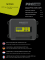
SCM30
MPPT Solar Panel Battery Controller
12V/24V WWW.PRO-USER.COM
OPERATING MANUAL P.2
BEDIENUNGSANLEITUNG P.13
GEBRUIKSAANWIJZING P.24
MODE D’EMPLOI P.35
MPPT SOLAR BATTERY CONTROLLER 30A
SUITABLE FOR STANDARD LEAD-ACID, AGM & LiFePO4 (12V) BATTERIES
SOLARMODUL-LADESTROMREGLER MPPT 30A
EIGNET SICH FÜR STANDARD BLEI-SÄURE, AGM & LiFePO4 (12V) BATTERIEN
ZONNEPANEEL LAADSTROOMREGELAAR MPPT 30A
GESCHIKT VOOR STANDAARD LOODZUUR, AGM & LiFePO4 (12V) ACCU'S
CONTRÔLEUR DE BATTERIE DE PANNEAU SOLAIRE MPPT 30A
POUR LES BATTERIES STANDARD PLOMP-ACIDE, AGM & LiFePO4 (12V)

2
Read this manual before using this product.
Failure to do so can result in serious injury.
CONTENTS
Important safety instruction & warnings P.2
Product specifications P.4
Wiring scheme / Explanations front & LCD screen P.5
LCD menu settings P.8
Load time settings P.9
Additional solar panel battery controller information / warnings P.10
Failures P.11
Temperature sensor P.11
Warranty P.12
SAVE THESE INSTRUCTIONS:
: :
: This manual contains important safety and
operating instructions for the Pro-User Electronics solar panel battery controller.
Pro-User Electronics accepts no liability for direct or indirect damage caused by faulty
assembly or connection, a usage of damaged or altered products, a usage for purposes other
than described and especially caused by failure to follow these instructions.
• Battery posts, terminals and related accessories contain lead and lead components, and other
chemicals known to the State of European to cause cancer and birth defects or other
reproductive harm. Always wash your hands after handling these devices.
• Do not operate the solar panel battery controller with damaged wiring. Replace wires imme-
diately if damaged.
• All lead acid batteries have the potential to emit gasses that may combine into a combustible
or explosive mixture. In many cases, it is possible that lead acid batteries will emit these
gasses during normal discharge and charging operations. Because of this potential danger, it
is important that you follow the precautions recommended by both the battery and battery
charger manufacturers before using either one. For example, do not exceed the recommen-
ded maximum recharge rate (charger output current limit), or remove cell caps while charging
flooded batteries.
• Install the solar panel battery controller as far away from the battery as possible and in a well
ventilated area.
• Do not expose the Solar Charger Controller to any rain, snow, spray, or moisture of any kind.
This device is not designed for outdoor use.
IMPORTANT SAFETY INSTRUCTIONS & WARNINGS

3
• Do not use attachments that are not recommended or sold by the charger manufacturer. To
do otherwise may result in the risk of electric shock, fire, or possibly some other unforeseen
potential personal injury situations.
• When leaving a battery charger connected to either a sealed (AGM or GEL) or non-sealed
(flooded battery) for extended periods of time (weeks, months, etc.), periodically check the
battery to see if it is unusually warm. This is an indication that the battery may have a weak
cell and that it could go into a thermal runaway condition. If the battery releases an excessi-
ve amount of gas or if the battery gets hotter than 55 degrees during charging, disconnect
the charger and allow the battery to cool. Overheating may result in plate distortion, internal
shorting, drying out or other damage. For flooded batteries, also check individual cell fluid
levels against manufacturer's recommendations for safe operation.
• Never smoke or allow a source of electric spark or open flame in the vicinity of the battery or
engine. (For example: don't charge the battery next to a gas water heater.)
• Do not operate the solar panel battery controller where ventilation is restricted. The intent
here is to allow sucient airflow to minimize and dissipate the heat generated by the Solar
Charger Controller and to diuse the gasses that may be emitted by the battery.
• Never disassemble or attempt to do internal repairs. This voids the warranty. Disassembling
the Solar Charger Controller incorrectly may result in the risk of electric shock or create a fire
hazard.
• Never charge a visibly damaged or frozen battery.
• After opening the package, examine all parts for visible damage. If you have found any
damage, please contact the company you purchased this unit from.
• Electrical devices are not toys. Keep the product away from children.
Personal precautions when you work near lead-acid batteries:
• Someone should be within range of your voice or close enough to come to your aid if you
have an accident.
• Have plenty of fresh water and soap nearby in case battery acid contacts skin, clothing, or
eyes.
• Wear complete eye protection and protective clothing. Avoid touching your eyes while
working near a battery. If battery acid contacts your skin or clothing, wash immediately with
soap and water. If acid enters an eye, immediately flood the eye with running cold water for
at least 10 minutes and get medical attention as soon as possible.
• Be extra cautious when handling metal tools around a battery. If you drop a metal tool near a
battery it might spark or create a short circuit between the battery terminals and some other
metal part. Either event may cause a dangerous electrical shock hazard, a fire, or even an
explosion.
• Remove all personal metal items such as rings, bracelets, necklaces, and watches when wor-
king with a lead-acid battery. A lead-acid battery can produce a short-circuited current high
enough to weld a metal ring or other piece of jewelry, causing a severe burn.

4
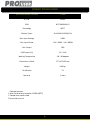
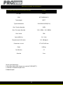
PRODUCT SPECIFICATIONS
Solar Panel Battery Controller SCM30
Max. Input Voltage 100V
Max. Input Power 12V / 450W - 24V / 900W
Max. Output 30A
USB Output (2x) 5V / 2.4A
Working Temperature -10 - 40 degrees
Dimensions LxWxH 177x237x63 mm
Weight 1450 gr.
Art. No. 18282
EAN 8717809182821
Technology MPPT
Battery Types SLA/AGM/LiFePO4(12V)
Certification CE
Warranty 2 Years
Package contents:
1. Solar panel battery controller SCM30 (MPPT)
2. Temperature sensor cable
3. Instruction manual

5
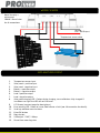
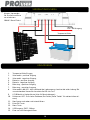
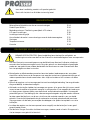
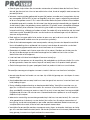
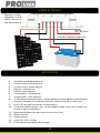
WIRING SCHEME
EXPLANATIONS FRONT
1. Temperature sensor input
2. Solar panel + positive input
3. Solar panel - negative input
4. Battery + positive output
5. Battery - negative output
6. Load + positive output
7. Load - negative output
8. Solar panel charging LED – flashes during charging, turns solid when fully charged. If
insucent sun light the LED will not illiminate.
9. LCD Screen (see next page for descriptions)
10. Error warning LED – Green no issues, Red inicates a fault (see failure section for details).
11. Scroll up and down menu buttons.
12. Enter/OK button
13. Menu button
14. USB output – 5VDC, 2.4Amp.
15. One of four mounting slots.
12V / 30A Output
Note: Use only a
minimum of
10AWG / 6mm2 wire
for all connections
Temperature sensor cable

6

7
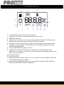
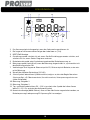
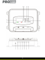
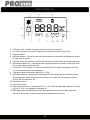
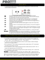
1. Sun icon displayed when solar panel is connected.
2. Sunlight rays, 8 in total, shows the charging current rate. (1-8).
3. PWM/MPPT indication.
4. Settings icon: turn on when entering the setting parameters and turn owhen exiting.
5. Battery level icon; displays icons according to the battery voltage.
6. Load icon: turns on when the load is turned on, synchronized with the load switch ON.
7. Connections: Three segments. Top corresponds to PV, middle corresponds to battery,
bottom corresponds to load.
8. Currently identified battery type (12/24V).
9. Protection icon. When this icon appears, it indicates that the controller has some
protection such as load overcurrent, short circuit protection, undervoltage protection, etc.
(Refer to the failure code).
10. Load timing clock 2.
11. Load timing clock 1.
12. Daytime and nighttime Icons. When PV is > 12V the half sun icon will appear. When PV is
<12V the half-moon icon will appear.
13. Numerical Display (8888 characters). Can be switched by the menu button to display
Battery Voltage/Load Voltage/PV voltage/time.
EXPLANATIONS LCD

8
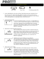
LCD MENU INSTELLINGEN
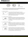
Menu button Enter button Settings icon (LCD)
To enter the menu screen press the menu button once, then press again and hold for two (2)
seconds. The settings icon will then appear and the first LCD settings screen will also appear. To
move to the next LCD settings screen press the menu button.
Battery type selection:
There are three (3) battery chemistry types to chose from. S=Standard lead acid. L=Lithium.
A=AGM. Press the enter button and the battery type will flash. Then use the up/down scroll but-
ton to change the battery type. Press enter button to set. Press menu button to move to the
next LCD screen.
Low voltage protection cut o value:
When your battery reaches this voltage the output load will be turned o. Press the enter button
and the voltage# will flash. Then use the up/down scroll button to change the voltage. Press
enter button to set. Default is set at 10.0V. Press menu button to move to the next LCD screen.
Low voltage recovery re-engage:
When your battery voltage has charged back up to this voltage the outload will reactivate. Press
the enter button and the voltage# will flash. Then use the up/down scroll button to change the
voltage. Press enter button to set. Default is set at 12.5V. Press menu button to move to the
next LCD screen.
Time Setting (24hr):
Set the time in 24hr format. Press the enter button and the hour# will flash. Then use the up/
down scroll button to change the hour. Press enter button to set. The minute# will then flash.
Then use the up/down scroll button to change the minutes. Press enter button to set . Pressme-
nu button to move to the next screen.

9
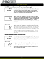
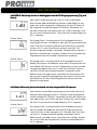
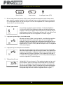
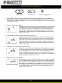
LdU MODE: Load on/o based on the PV input voltage (Day and night):
LdU MODE: Load on/o based on the PV input voltage (Day and night): LdU MODE: Load on/o based on the PV input voltage (Day and night):
LdU MODE: Load on/o based on the PV input voltage (Day and night):
When the PV input voltage drops below 10V (during the night hours
or cloud cover) you can set the regulator to activate the output load
automatically. Press the enter button and the OFF/ON will flash.
Then use the up/down scroll button to change to ON. Press enter
button to set. The clock 1 screen will then appear.
Clock 1 screen
Clock 1 symbol is on. The default is sixty (60) minutes. This means
when the PV input voltage drops below 10V, sixty (60) minutes later
the load output will be activated. Clock 1 is a power on timer and can
be set from 0 to 120 minutes. Use the up/down scroll button to
change the minutes. Press enter button to set. The clock screen will
then appear.
Clock 2 screen
Clock 2 symbol is on. The default is thirty (30) minutes. This means
when the PV input voltage rises to 12.5V (morning time) after thirty
(30) minutes the output load will be shut o. Clock 2 is a power o
timer and can be set from 0 to 120 minutes. Use the up/down scroll
button to change the minutes. Press enter button to set . This will
then take you back to the LdU screen, Press enter to move to the
next screen.
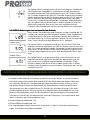
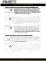
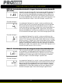
Ld1 mode: Load on/o based on a set length of time:
Ld1 mode: Load on/o based on a set length of time: Ld1 mode: Load on/o based on a set length of time:
Ld1 mode: Load on/o based on a set length of time:
This allows you to set the load output to be active for a set length of
time. Press the enter button and the OFF/ON will flash. Then use the
up/down scroll button to change to ON. Press enter button to set.
The clock 1 screen will then appear.
Clock 1 screen
Clock 1 symbol is on. The default is three (3) hours. This means when
the PV input voltage drops below 10V, the output load will be active
for 3 hours. This can be set from 0 to 12 hours. Use the up/down
scroll button to change the minutes. Press enter button to set. The
clock 2 screen will then appear.
LOAD TIME SETTINGS

10
Clock 2 Screen
Clock 2 symbol is on. This timer will begin after the clock 1 counting
has finished. In this case, after the PV input voltage has dropped to
10V (night hours), the output load will power on for 3 hours, then
switch o for 4 hours, then back on again until the PV input voltage
has risen to 12.5V at witch time the load will be cut o. This can be
set from 0 to 12 hours. Use the up/down scroll button to change the
minutes. Press enter button to set. This will then take you back to
the Ld1 screen, Press enter to move to the next screen.
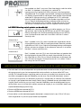
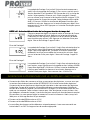
LdS MODE: Load On/O based on the real time
LdS MODE: Load On/O based on the real timeLdS MODE: Load On/O based on the real time
LdS MODE: Load On/O based on the real time
This allows you to set the output load based on 24 hour time
(military time). Press the enter button and the OFF/ON will flash.
Then use the up/down scroll button to change to ON. Press enter
button to set. The clock 1 screen will then appear.
Clock 1 screen
Clock 1 symbol is on. This is a power on timer, and means the output
load will be activated at 5.00. This can be set from 0 to 24 hours.
Use the up/down scroll button to change the hours minutes. Press
enter button to set. The clock 2 screen will then appear.
Clock 2 screen
Clock 2 symbol is on. This is a power o timer, and means the output
load will will shut o at 6.00. This can be set from 0 to 24 hours. Use
the up/down scroll button to change the hours minutes. Press enter
button to set. This will then take you back to the LDs screen
• Wire the solar panels cables into the connector on the controller; make sure the solar panel
input voltage DOES NOT exceed the max limit of the controller. Wire up the battery’s positive
and negative terminals to the correct connector on the controller (marked by the battery
image). The controller will automatically detect the battery voltage scale it is connected to
and charge. The switchable output is marked with a bulb. This output is designed to run a
modest load(s), such as lights. Read the manual for the full workings of the controller as you
can adjust time as to when the output switches on and o ideal for something like security
lighting.
• Maximum 450W solar panel at 12V.
• Maximum 900W solar panel at 24V.
• The solar charger controller will automatically detect if you have connected up to a 12V or
24V battery. It will then charge appropriately.
ADDITIONAL SOLAR PANEL BATTERY CONTROLLER INFORMATION/WARNINGS

11
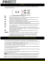
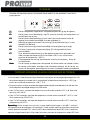
THE RED ERROR LED ON THE FRONT PANEL WILL BE RED IF THERE IS A FAiLURE WITH THE
OUTPUT REGULATOR.
E1
E1E1
E1
Battery reverse connection / reverse polarity (please correct).
E2
E2E2
E2
Battery open circuit protection / low DC voltage (battery not connected / or
battery voltage too low.
E3
E3E3
E3
Battery over current protection (circuit has constant current function; the
controller may be damaged if there is a problem).
E4
E4E4
E4 Load over current / short circuit protection (Turn on the load after eliminating
the error).
E5
E5E5
E5
Battery over voltage (battery damaged or battery voltage too high).
E6
E6E6
E6
PV (solar) input over voltage protection. (PV voltage has exceeded the limit).
E7
E7E7
E7
Over temperature protection, controller will automatically stop charging when
the heat sink temperature is ≥ 90°C; and will resume when the temperature is
≤ 60°C.
E8
E8E8
E8
PV reverse connection (check the voltage and correct) - please ensure polarity is
correct.
Note:
Note: Note:
Note:
Please eliminate the fault according to the error code. If the controller does not
respond after the error is eliminated remove the power source (battery). If the
error persists the controller may be damaged and may need servicing.
• The system will automatically adjust the float voltage according to the ambient temperature.
If the external temperature probe is not connected (or the external temperature is <40°C), it
uses (temperature ≥ 20°C - 5°C) by default.
• The voltage may vary when the input energy is insucient to stabilize the energy required
for the float charging.
• For 12/24V batteries, when the external probe temperature ≤ 0°C, the float charging voltage
is 14.1/28.2V.
• For 12/24V batteries, when the external probe temperature is 0°C~20°C, the float charging
voltage is 13.8/27.6V.
• For 12/24V batteries, when the external probe temperature ≥ 20°C, the float charging
voltage is 13.5/27V.
Note:
Note: Note:
Note: If internal head sink temperature exceeds 80°C, the device shall go into approxima-
tely half power mode. Shall resume normal operation when internal head sink drops below 75°C
If internal head sink exceeds 90°C, the device shall turn o. It will resume charging again when
temperature drops below 60°C.
FAILURES
TEMPERATURE SENSOR (ONLY LEAD ACID/AGM BATTERIES)

12
WARRANTY
Pro-User Electronics warrants this product for a period of 2 years from the date of purchase
to the original purchaser. Warranty is not transferable. Warranty covers defect against
workmanship and materials only. To obtain warranty service, please return the unit to the
place of purchase or authorized Pro-User Electronics dealer together with your proof of
purchase. The warranty is void if the product has been damaged or not used as described in
this manual. Warranty is void if a non-authorized repair has been performed. Pro-User Electro-
nics makes no other warranty expressed or implied. Pro-User Electronics is only responsible
for repair or replacement of the defective product and is not responsible for any
consequential damage or inconvenience caused by the defect.
Contact information:
Tradekar Benelux BV
Ohmweg 1
4104 BM Culemborg
The Netherlands
+31(0)345470990
Pro-User Electronics is part of Tradekar House of Leisure Brands
WWW.PRO
WWW.PROWWW.PRO
WWW.PRO-
--
-USER.COM
USER.COMUSER.COM
USER.COM

13
Lesen Sie dieses Betriebsanleitung, bevor Sie dieses Produkt benutzen.
Eine Nichtbeachtung kann zu schweren Verletzungen führen.
INHALT
Wichtige Sicherheitsanweisungen und Warnhinweise P.13
Produktspezifikationen P.15
Verdrahtungsschema/ Erklärungen & LCD-Bildschirm P.16
LCD-Menü-Einstellungen P.19
Einstellungen der Belastungszeit P.20
Zusätzliche Informationen/Warnungen zum Solarmodul-Ladestromregler P.21
Fehler P.22
Temperaturfühler P.22
Garantie P.22
BEWAHREN SIE DIESE ANLEITUNG AUF: Dieses Betriebsanleitung enthält wichtige
Sicherheits- und Betriebsanweisungen für den Pro-User Electronics Solarmodul-
Ladestromregler.
Pro-User Electronics übernimmt keine Haftung für direkte oder indirekte Schäden, die durch
eine fehlerhafte Montage oder einen fehlerhaften Anschluss, eine Verwendung von
beschädigten oder veränderten Produkten, eine Verwendung für andere als die beschriebe-
nen Zwecke und insbesondere durch die Nichtbeachtung dieser Anleitung entstehen.
• Batteriepole, -klemmen und zugehöriges Zubehör enthalten Blei und Bleibestandteile sowie
andere Chemikalien, die dem Staat Europa als krebserregend, geburtsschädigend oder
fortpflanzungsgefährdend bekannt sind. Waschen Sie sich nach dem Umgang mit diesen
Geräten immer die Hände.
• Betreiben Sie den Solarmodul-Ladestromregler nicht mit beschädigter Verkabelung. Ersetzen
Sie beschädigte Kabel sofort.
• Alle Blei-Säure-Batterien können Gase freisetzen, die sich zu einem brennbaren oder
explosiven Gemisch verbinden können. In vielen Fällen ist es möglich, dass Blei-Säure-
Batterien diese Gase während des normalen Entlade- und Ladevorgangs freisetzen. Aufgrund
dieser potenziellen Gefahr ist es wichtig, dass Sie die vom Hersteller der Batterie und des
Batterieladegeräts empfohlenen Vorsichtsmaßnahmen beachten, bevor Sie eine der beiden
Batterien verwenden. Überschreiten Sie z. B. nicht die empfohlene maximale
Ladegeschwindigkeit (Ausgangsstromgrenze des Ladegeräts) und entfernen Sie beim Laden
von gefluteten Batterien nicht die Zellendeckel.
• Installieren Sie den Solarmodul-Batterieregler so weit wie möglich von der Batterie entfernt
und an einem gut belüfteten Ort.
• Setzen Sie den Solarladeregler nicht Regen, Schnee, Spritzwasser oder Feuchtigkeit jeglicher
Art aus. Dieses Gerät ist nicht für den Außeneinsatz geeignet.
WICHTIGE SICHERHEITSANWEISUNGEN UND WARNHINWEISE

14
• Verwenden Sie keine Zubehörteile, die nicht vom Hersteller des Ladegeräts empfohlen oder
verkauft werden. Andernfalls besteht die Gefahr eines elektrischen Schlages, eines Feuers
oder einer anderen unvorhergesehenen Situation, die zu Verletzungen führen kann.
• Wenn Sie ein Batterieladegerät über einen längeren Zeitraum (Wochen, Monate usw.) an eine
verschlossene (AGM- oder GEL-Batterie) oder nicht verschlossene (geflutete) Batterie
angeschlossen lassen, sollten Sie die Batterie regelmäßig darauin überprüfen, ob sie
ungewöhnlich warm ist. Dies ist ein Anzeichen dafür, dass die Batterie möglicherweise eine
schwache Zelle hat und in einen thermischen Durchlaufzustand geraten könnte. Wenn die
Batterie übermäßig viel Gas abgibt oder während des Ladevorgangs heißer als 55 Grad wird,
Trennen Sie das Ladegerät ab und lassen Sie die Batterie abkühlen. Überhitzung kann zu
Plattenverformung, internem Kurzschluss, Austrocknung oder anderen Schäden führen.
Überprüfen Sie bei gefluteten Batterien auch den Flüssigkeitsstand der einzelnen Zellen
anhand der Empfehlungen des Herstellers für einen sicheren Betrieb.
• In der Nähe der Batterie oder des Motors darf nicht geraucht werden, und es darf keine
Funkenquelle oder oene Flamme vorhanden sein. (Beispiel: Laden Sie die Batterie nicht
neben einem Gas-Wassererhitzer auf).
• Betreiben Sie den Solarladeregler nicht an Orten, an denen die Belüftung eingeschränkt ist.
Damit soll ein ausreichender Luftstrom gewährleistet werden, um die vom Solarladeregler
erzeugte Wärme zu minimieren und abzuführen und die von der Batterie möglicherweise
abgegebenen Gase zu verteilen.
• Versuchen Sie niemals, das Gerät zu zerlegen oder interne Reparaturen durchzuführen.
Dadurch wird die Garantie ungültig. Wenn Sie den Solarladeregler unsachgemäß zerlegen,
besteht die Gefahr eines elektrischen Schlags oder Brandgefahr.
• Überprüfen Sie nach dem Önen der Verpackung alle Teile auf sichtbare Schäden. Wenn Sie
einen Schaden gefunden haben, wenden Sie sich bitte an das Unternehmen, bei dem Sie das
Gerät gekauft haben.
• Elektrische Geräte sind kein Spielzeug. Halten Sie das Produkt von Kindern fern.
Persönliche Vorsichtsmaßnahmen bei Arbeiten in der Nähe von Blei-Säure-Batterien:
• Jemand sollte in Reichweite Ihrer Stimme sein oder nahe genug, um Ihnen bei einem Unfall zu
Hilfe zu kommen.
• Halten Sie reichlich frisches Wasser und Seife bereit, falls Batteriesäure mit Haut, Kleidung
oder Augen in Berührung kommt.
• Tragen Sie einen vollständigen Augenschutz und Schutzkleidung. Berühren Sie bei der Arbeit
in der Nähe einer Batterie nicht Ihre Augen. Wenn Batteriesäure mit Ihrer Haut oder Kleidung
in Berührung kommt, waschen Sie sie sofort mit Wasser und Seife ab. Wenn Säure in ein Auge
gelangt, spülen Sie das Auge sofort mindestens 10 Minuten lang mit fließendem kaltem
Wasser aus und suchen Sie so schnell wie möglich einen Arzt auf.
• Seien Sie besonders vorsichtig beim Umgang mit Metallwerkzeugen in der Nähe einer
Batterie. Wenn Sie ein Metallwerkzeug in der Nähe einer Batterie fallen lassen, kann es
Funken schlagen oder einen Kurzschluss zwischen den Batteriepolen und einem anderen
Metallteil verursachen. Beides kann zu einem gefährlichen elektrischen Schlag, einem Brand
oder sogar einer Explosion führen.
• Legen Sie alle persönlichen Metallgegenstände wie Ringe, Armbänder, Halsketten und Uhren
ab, wenn Sie mit einer Bleisäurebatterie arbeiten. Ein Blei-Säure-Akku kann einen
Kurzschlussstrom erzeugen, der hoch genug ist, um einen Metallring oder ein anderes
Schmuckstück zu verschweißen und schwere Verbrennungen zu verursachen.

15
PRODUKTSPEZIFIKATIONEN
SOLARMODUL-LADESTROMREGLER SCM30
Max. Eingangsspannung 100V
Max. Eingangsleistung 12V / 450W - 24V / 900W
Max. Ausgang 30A
USB Ausgang (2x) 5V / 2.4A
Betriebstemperatur -10 - 40 Grad
Abmessungen LxBxH 177x237x63 mm
Gewicht 1450 gr.
Art. Nr. 18282
EAN 8717809182821
Technologie MPPT
Batterie-Typen SLA/AGM/LiFePO4(12V)
Zertifizierung CE
Garantie 2 Jahre
Verpackungsinhalt:
1. Solarmodul-Ladestromregler SCM30 (MPPT)
2. Temperaturfühler
3. Bedienungsanleitung

16
VERDRAHTUNGSSCHEMA
ERKLÄRUNGEN
1. Temperaturfühler Eingang
2. Solarmodul + positiver Eingang
3. Solarmodul - negativer Eingang
4. Batterie + positiver Ausgang
5. Batterie - negativer Ausgang
6. Belastung + positiver Ausgang
7. Belastung - negativer Ausgang
8. Solarmodul-Lade-LED - blinkt während des Ladevorgangs, leuchtet bei voller Ladung. Bei
unzureichendem Sonnenlicht leuchtet die LED nicht auf.
9. LCD-Bildschirm (siehe nächste Seite für Beschreibungen)
10. Fehlerwarn-LED - Grün: keine Probleme, Rot: Fehler (siehe "Fehler" für weitere Informati-
onen).
11. Menütasten nach oben und unten blättern.
12. Enter/OK-Taste
13. Menu Taste
14. USB Ausgang– 5VDC, 2.4Amp.
15. Einer von vier Montageschlitzen.
12V / 30A Ausgang
Hinweis: Verwenden
Sie für alle Anschlüsse
nur mindestens
10AWG / 6mm2 Draht.
Temperaturfühler

17

18
1. Das Sonnensymbol wird angezeigt, wenn das Solarpanel angeschlossen ist.
2. Die insgesamt 8 Sonnenstrahlen zeigen den Ladestrom an. (1-8).
3. MPPT/PWM-Anzeige.
4. Einstellungssymbol: schaltet sich ein, wenn Sie die Einstellungsparameter aufrufen, und
schaltet sich aus, wenn Sie das Programm verlassen.
5. Batteriestandssymbol; zeigt Symbole entsprechend der Batteriespannung an.
6. Belastungssymbol: leuchtet auf, wenn die Belastung eingeschaltet ist, synchronisiert mit
dem Belastungsschalter ON.
7. Verbindungen: Drei Segmente. Oben entspricht PV, Mitte entspricht Batterie, unten ents-
pricht Belastung.
8. Aktuell identifizierter Batterietyp (12/24V).
9. Schutz-Symbol. Wenn dieses Symbol erscheint, zeigt es an, dass der Regler über einen
Schutz verfügt, z. B. Überstromschutz, Kurzschlussschutz, Unterspannungsschutz usw.
(siehe Fehlercode).
10. Belastung Zeitgeber 2.
11. Belastung Zeitgeber 2.
12. Tag- und Nachtsymbole. Wenn PV > 12V ist, erscheint das Symbol der halben Sonne.
Wenn PV <12 V ist, erscheint das Halbmond-Symbol.
13. Numerische Anzeige (8888 Zeichen). Kann mit der Menütaste umgeschaltet werden, um
Batteriespannung/Ladespannung/PV-Spannung/Zeit anzuzeigen.
ERKLÄRUNGEN LCD

19
LCD MENU SETTINGS
Menu Taste Enter Taste Einstellungssymbol (LCD)
1. Um den Menübildschirm aufzurufen, drücken Sie die Menütaste einmal und halten Sie sie
dann noch einmal für zwei (2) Sekunden gedrückt. Darauin erscheint das Einstellungs-
symbol und der erste LCD-Einstellungsbildschirm wird ebenfalls angezeigt. Um zum nächsten
LCD-Einstellungsbildschirm zu gelangen, drücken Sie die Menütaste.
2. Auswahl des Batterietyps:
Es stehen drei (3) Batterietypen zur Auswahl. S=Standard Bleisäure.
L=Lithium. A=AGM. Drücken Sie die Eingabetaste und der Batterietyp
wird blinken. Verwenden Sie dann die Bildlauftasten nach oben/
unten, um den Batterietyp zu ändern. Drücken Sie zum Einstellen die
Eingabetaste. Drücken Sie die Menütaste, um zum nächsten LCD-
Bildschirm zu gelangen.
3. Abschaltwert für den Unterspannungsschutz:
Wenn Ihre Batterie diese Spannung erreicht, wird die Ausgangslast
abgeschaltet. Drücken Sie die Eingabetaste und die Spannung# wird
blinken. Ändern Sie dann die Spannung mit den Auf-/Ab-Tasten.
Drücken Sie zum Einstellen die Enter-Taste. Die Standardeinstellung
ist 10,0 V. Drücken Sie die Menütaste, um zum nächsten LCD-
Bildschirm zu gelangen.
4. Wiedereinschaltung der Niederspannungswiederkehr:
Wenn Ihre Batteriespannung wieder auf diese Spannung aufgeladen
ist, wird die Entlastung wieder aktiviert. Drücken Sie die Eingabetas-
te und die Spannung# wird blinken. Ändern Sie dann die Spannung
mit den Auf-/Ab-Tasten. Drücken Sie zum Einstellen die Enter-Taste.
Die Standardeinstellung ist 12,5 V. Drücken Sie die Menütaste, um
zum nächsten LCD-Bildschirm zu gelangen.
5. Zeiteinstellung (24 Stunden):
Stellen Sie die Zeit im 24-Stunden-Format ein. Drücken Sie die
Eingabetaste und die Stundenzahl blinkt. Verwenden Sie dann die
Auf-/Ab-Taste, um die Stunde zu ändern. Drücken Sie zum Einstellen
die Eingabetaste. Die Minutennummer blinkt dann. Ändern Sie dann
mit den Auf-/Ab-Tasten die Minuten. Drücken Sie zum Einstellen die
Eingabetaste. Drücken Sie die Menütaste, um zum nächsten Bld-
schirm zu gelangen.

20
LdU
LdULdU
LdU-
--
-MODUS: Belastung ein/aus in Abhängigkeit von der PV
MODUS: Belastung ein/aus in Abhängigkeit von der PVMODUS: Belastung ein/aus in Abhängigkeit von der PV
MODUS: Belastung ein/aus in Abhängigkeit von der PV-
--
-Eingangsspannung (Tag und
Eingangsspannung (Tag und Eingangsspannung (Tag und
Eingangsspannung (Tag und
Nacht):
Nacht):Nacht):
Nacht):
Wenn die PV-Eingangsspannung unter 10 V fällt (während der
Nachtstunden oder bei Bewölkung), können Sie den Regler so eins-
tellen, dass er die Ausgangslast automatisch aktiviert. Drücken Sie
die Eingabetaste und die Anzeige OFF/ON blinkt. Verwenden Sie
dann die Scrolltasten nach oben/unten, um zu ON zu wechseln. Drüc-
ken Sie zum Einstellen die Enter-Taste. Darauin wird der Bildschirm
Uhr 1 angezeigt.
Display Clock 1
Das Symbol Clock 1 ist eingeschaltet. Die Standardeinstellung ist
sechzig (60) Minuten. Das bedeutet, wenn die PV-Eingangsspannung
unter 10 V fällt, wird sechzig (60) Minuten später der Lastausgang
aktiviert. Uhr 1 ist ein Einschalttimer und kann von 0 bis 120
Minuten eingestellt werden. Verwenden Sie die Aufwärts-/Abwärts-
Rolltaste, um die Minuten zu ändern. Drücken Sie zum Einstellen die
Eingabetaste. Darauin wird der Uhrbildschirm angezeigt.
Display Clock 2
Das Symbol Clock 2 ist eingeschaltet. Die Standardeinstellung ist
dreißig (30) Minuten. Das bedeutet, wenn die PV-Eingangsspannung
nach dreißig (30) Minuten auf 12,5 V (Morgenzeit) ansteigt, wird die
Ausgangslast abgeschaltet. Uhr 2 ist ein Ausschalttimer und kann
von 0 bis 120 Minuten eingestellt werden. Verwenden Sie die
Bildlauftasten nach oben/unten, um die Minuten einzustellen. Drüc-
ken Sie zum Einstellen die Eingabetaste. Dies bringt Sie zurück zum
LdU-Bildschirm. Drücken Sie die Eingabetaste, um zum nächsten
Bildschirm zu gelangen.
Ld1
Ld1Ld1
Ld1-
--
-Modus: Belastung ein/aus basierend auf einer eingestellten Zeitspanne:
Modus: Belastung ein/aus basierend auf einer eingestellten Zeitspanne:Modus: Belastung ein/aus basierend auf einer eingestellten Zeitspanne:
Modus: Belastung ein/aus basierend auf einer eingestellten Zeitspanne:
Damit können Sie den Belastungsausgang so einstellen, dass er für
eine bestimmte Zeitspanne aktiv ist. Drücken Sie die Eingabetaste
und die Anzeige OFF/ON blinkt. Verwenden Sie dann die Scrolltasten
nach oben/unten, um zu ON zu wechseln. Drücken Sie zum Einstellen
die Enter-Taste. Darauin wird der Bildschirm Uhr 1 angezeigt.
Display Clock 1
Das Symbol Clock 1 ist eingeschaltet. Die Standardeinstellung ist
drei (3) Stunden. Das bedeutet, wenn die PV-Eingangsspannung
unter 10 V fällt, ist die Ausgangslast für 3 Stunden aktiv. Dies kann
von 0 bis 12 Stunden eingestellt werden. Verwenden Sie die
Bildlauftasten nach oben/unten, um die Minuten zu ändern. Drücken
Sie zum Einstellen die Eingabetaste. Darauin wird der Bildschirm
Uhr 2 angezeigt.
LOAD TIME SETTINGS
Seite wird geladen ...
Seite wird geladen ...
Seite wird geladen ...
Seite wird geladen ...
Seite wird geladen ...
Seite wird geladen ...
Seite wird geladen ...
Seite wird geladen ...
Seite wird geladen ...
Seite wird geladen ...
Seite wird geladen ...
Seite wird geladen ...
Seite wird geladen ...
Seite wird geladen ...
Seite wird geladen ...
Seite wird geladen ...
Seite wird geladen ...
Seite wird geladen ...
Seite wird geladen ...
Seite wird geladen ...
Seite wird geladen ...
Seite wird geladen ...
Seite wird geladen ...
Seite wird geladen ...
Seite wird geladen ...
Seite wird geladen ...
-
 1
1
-
 2
2
-
 3
3
-
 4
4
-
 5
5
-
 6
6
-
 7
7
-
 8
8
-
 9
9
-
 10
10
-
 11
11
-
 12
12
-
 13
13
-
 14
14
-
 15
15
-
 16
16
-
 17
17
-
 18
18
-
 19
19
-
 20
20
-
 21
21
-
 22
22
-
 23
23
-
 24
24
-
 25
25
-
 26
26
-
 27
27
-
 28
28
-
 29
29
-
 30
30
-
 31
31
-
 32
32
-
 33
33
-
 34
34
-
 35
35
-
 36
36
-
 37
37
-
 38
38
-
 39
39
-
 40
40
-
 41
41
-
 42
42
-
 43
43
-
 44
44
-
 45
45
-
 46
46


in anderen Sprachen
- English: Pro-User 16434 Owner's manual
- français: Pro-User 16434 Le manuel du propriétaire
- Nederlands: Pro-User 16434 de handleiding
Verwandte Artikel
Andere Dokumente
-
Victron energy SmartSolar MPPT 150/45 up to 150/100 & 250/60 up to 250/100 Bedienungsanleitung
-
-
-
-
-
-
-
Goalzero GZ96110 Benutzerhandbuch
-
Western WRM20 Bedienungsanleitung
-
tbs electronics OCS 250-70 Bedienungsanleitung