ENCELIUM PS 30 Power Supply Benutzerhandbuch
- Typ
- Benutzerhandbuch

System Infrastructure and Accessories | Installation Instructions | Installationsanleitung | Instructions d'installation | Instrucciones de Instalación
OVERVIEW
ÜBERBLICK
APERÇU
VISIÓN GENERAL
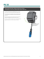
The PS 30 power supply has an output voltage of 24 VDC
and output current of 1.3 A. It is suitable for a wide-range of
applications and has a large input voltage range, so you are
bound to find it useful in many professional lighting projects.
For more information on product specifications and design
tools visit encelium.com.
Das Netzteil PS 30 hat eine Ausgangsspannung von 24 VDC und
einen Ausgangsstrom von 1,3 A. Es eignet sich für eine Vielzahl von
Anwendungen und hat einen großen Eingangsspannungsbereich,
sodass Sie es in vielen professionellen Beleuchtungsprojekten
nützlich finden werden . Weitere Informationen zu
Produktspezifikationen und Designtools Besuchen Sie encelium.com.
L'alimentation PS 30 a une tension de sortie de 24 VDC et un courant
de sortie de 1,3 A. Elle convient à un large éventail d'applications et
possède une large plage de tension d'entrée, vous la trouverez donc
utile dans de nombreux projets d'éclairage professionnels. Pour plus
d'informations sur les spécifications des produits et les outils de
conception visitez encelium.com.
La fuente de alimentación PS 30 tiene una tensión de salida de 24 V
CC y una corriente de salida de 1,3 A. Es adecuada para una amplia
gama de aplicaciones y tiene un amplio rango de tensión de entrada,
por lo que seguramente la encontrará útil en muchos proyectos de
iluminación profesional. Para obtener más información sobre las
especificaciones del producto y las herramientas de diseño
visite encelium.com.
PS 30
PS 30 Power Supply | Netzteil PS 30 |
Alimentation PS30 | Fuente de alimentación PS30
GETTING STARTED | EINSTIEG |
COMMENCER | EMPEZANDO

2PS 30 Installation Instructions | Installationsanleitung | Instructions d'installation | Instrucciones de Instalación
PS 30
PRODUCT SAFETY | PRODUKTSICHERHEIT | SÉCURITÉ DES PRODUITS | SEGURIDAD DEL PRODUCTO
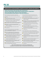
When using electrical equipment, basic safety
precautions should always be followed, including the
following:
Do not mount near gas or electric heaters or let power
supply cords touch hot surfaces.
Equipment should be mounted in locations and at
heights where it will not readily be subjected to
tampering by unauthorized personnel.
The use of accessory equipment is not recommended
by Encelium as it may cause an unsafe condition.
All DALI channels are internally connected
together to the control unit. Make sure to consider
this when installing.
Do not use this equipment for other than the
intended use.
Bei der Verwendung elektrischer Geräte sollten
immer grundlegende Sicherheitsvorkehrungen getroffen
werden, einschließlich der folgenden:
Montieren Sie das Gerät nicht in der Nähe von
Gas- oder Elektroheizungen und lassen Sie die
Netzkabel keine heißen Oberflächen berühren.
Die Ausrüstung sollte an Orten und in Höhen montiert
werden, an denen sie nicht leicht von unbefugtem
Personal manipuliert werden können.
Die Verwendung von Zubehörgeräten wird von
Encelium nicht empfohlen, da dies zu einem
unsicheren Zustand führen kann.
Alle DALI-Kanäle sind intern verbunden zusammen
mit dem Steuergerät. Berücksichtigen Sie dies
unbedingt bei der Installation.
Verwenden Sie dieses Gerät nicht für andere als die
bestimmungsgemäße Verwendung.
Lors de l'utilisation d'équipements électriques, des
précautions de sécurité de base doivent toujours être
suivies, notamment les suivantes:
Ne pas monter près de radiateurs à gaz ou électriques
ou laisser les cordons d'alimentation toucher des
surfaces chaudes.
L'équipement doit être monté à des emplacements et à
des hauteurs où il ne sera pas facilement soumis à des
manipulations par du personnel non autorisé.
L'utilisation d'équipements accessoires n'est pas
recommandée par Encelium car cela peut entraîner
une situation dangereuse.
Tous les canaux DALI sont connectés en interne
ensemble à l'unité de commande. Assurez-vous d'en
tenir compte lors de l'installation.
N'utilisez pas cet équipement à d'autres fins que
l'usage prévu.
Al usar equipo eléctrico, siempre se deben seguir las
precauciones básicas de seguridad, incluidas las siguientes:
No lo monte cerca de calentadores de gas o eléctricos
ni permita que los cables de alimentación toquen
superficies calientes.
El equipo debe montarse en lugares y en alturas donde
no pueda ser fácilmente manipulado por personal no
autorizado.
Encelium no recomienda el uso de equipos accesorios,
ya que puede causar una condición peligrosa.
Todos los canales DALI están conectados
internamente juntos a la unidad de control. Asegúrese
de tener esto en cuenta al instalar.
No utilice este equipo para otro uso que no sea
el indicado.
SAVE THESE INSTRUCTIONS. | ANLEITUNG AUFBEWAHREN.
CONSERVEZ CES INSTRUCTIONS. | GUARDA ESTAS INSTRUCCIONES.
READ THESE INSTRUCTIONS BEFORE USING THE PRODUCT
LESEN SIE DIESE ANWEISUNGEN BEVOR SIE DIESES PRODUKT VERWENDEN
LIRE CES INSTRUCTIONS AVANT D'UTILISER CE PRODUIT
LEA ESTAS INSTRUCCIONES ANTES DE USAR ESTE PRODUCTO

3
PS 30 Installation Instructions | Installationsanleitung | Instructions d'installation | Instrucciones de Instalación
PS 30
Terminal Block
Klemmenblock
Bornier
Bloque de Terminales
STEP 1 | SCHRITT 1 | ÉTAPE 1 | PASO 1
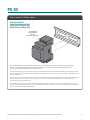
The PS 30 should be vertically mounted so that the terminal block is at the top. A clearance of at least 20 mm
(0.8 inch) should be maintained above and below. No space is required at the side. The PS 30 snaps onto a
35 mm (1.4 inches) DIN Rail within an electrical panel.
Der PS 30 sollte senkrecht montiert werden, so dass der Klemmblock oben ist. Ein Abstand von mindestens 20 mm (0.8 inch) sollte
oben und unten beibehalten werden. Seitlich wird kein Platz benötigt. Das PS 30 rastet auf a 35 mm (1.4 inches) DIN-Schiene innerh-
alb einer Schalttafel.
Le PS 30 doit être monté verticalement de manière à ce que le bornier soit en haut. Un dégagement d'au moins 20 mm (0.8 inch) doit
être maintenu au-dessus et au-dessous. Aucun espace n'est requis sur le côté. La PS 30 s'enclenche sur un Rail DIN de 35 mm
(1.4 inches) dans un panneau électrique.
El PS 30 debe montarse verticalmente de modo que el bloque de terminales quede en la parte superior. Una holgura de al menos
20 mm (0.8 inch) debe mantenerse por encima y por debajo. No se requiere espacio en el lateral. La PS 30 encaja en un Carril DIN de
35 mm (1.4 inches) dentro de un panel eléctrico.
DIN RAIL MOUNT
DIN-SCHIENENMONTAGE
MONTAGE SUR RAIL DIN
MONTAJE EN CARRIL DIN

4PS 30 Installation Instructions | Installationsanleitung | Instructions d'installation | Instrucciones de Instalación
PS 30
PS 30
Power Supply
Netzteil
Source de Courant
Fuente de Alimentación
+-
-24
VDC
+24
VDC
+-
LINE / LINIE /
LIGNE / LÍNEA
NEUTRAL / NEUTRAL /
NEUTRE / NEUTRAL
To Wired Manager — DALI or DALI Switch SO
An Wired Manager – DALI oder DALI Switch SO
Vers Wired Manager — DALI ou DALI Switch SO
Al administrador cableado: DALI o DALI Switch SO
STEP 2 | SCHRITT 2 | ÉTAPE 2 | PASO 2
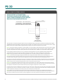
The Input AC is connected using terminal Line 1 (L1) and Neutral (N), and must be connected according to IEC 60364
and EN 50178. The Output DC is connected via the +24 VDC and -24 VDC terminals at the output of the power supply.
Make sure that the output cables are positioned correctly for the maximum output current value.
Notes: A protective device (miniature circuit-breaker or circuit-breaker) and a disconnection unit for the power supply
must be provided. A ground-fault circuit interrupter must not be used as the only protective measure against indirect
contact; this applies to the entire supply system that is protected by the residual current operated circuit-breaker.
Der AC-Eingang wird über die Klemme Line 1 (L1) und Neutral (N) angeschlossen und muss gemäß IEC 60364 und EN 50178
angeschlossen werden. Der DC-Ausgang wird über die Klemmen +24 VDC und -24 VDC am Ausgang des angeschlossen
Energieversorgung. Stellen Sie sicher, dass die Ausgangskabel für den maximalen Ausgangsstromwert richtig positioniert sind.
Hinweise: Eine Schutzeinrichtung (Leitungsschutzschalter oder Leitungsschutzschalter) und eine Trenneinrichtung für die
Stromversorgung sind vorzusehen. Ein Fehlerstromschutzschalter darf nicht als einzige Schutzmaßnahme gegen indirektes Berühren
verwendet werden; dies gilt für das gesamte Versorgungssystem, das durch den Fehlerstromschutzschalter geschützt wird.
L'entrée AC est connectée à l'aide des bornes Ligne 1 (L1) et Neutre (N) et doit être connectée conformément aux normes CEI 60364
et EN 50178. La sortie DC est connectée via les bornes +24 VDC et -24 VDC à la sortie du source de courant. Assurez-vous que les
câbles de sortie sont correctement positionnés pour la valeur maximale du courant de sortie.
Remarques: Un dispositif de protection (disjoncteur miniature ou disjoncteur) et un bloc de déconnexion de l'alimentation doivent
être prévus. Un disjoncteur de fuite à la terre ne doit pas être utilisé comme seule mesure de protection contre les contacts indirects;
cela s'applique à l'ensemble du système d'alimentation qui est protégé par le disjoncteur à courant résiduel.
La Entrada de CA se conecta mediante el terminal Línea 1 (L1) y Neutro (N), y debe conectarse de acuerdo con IEC 60364 y EN 50178.
La Salida de CC se conecta a través de los terminales +24 VCC y -24 VCC en la salida del fuente de alimentación. Asegúrese de que los
cables de salida estén colocados correctamente para el valor máximo de corriente de salida.
Notas: Se debe prever un dispositivo de protección (interruptor magnetotérmico o disyuntor) y una unidad de desconexión de la
alimentación. Un interruptor de circuito de falla a tierra no debe usarse como la única medida de protección contra el contacto indirecto;
esto se aplica a todo el sistema de suministro que está protegido por el interruptor automático accionado por corriente residual.
MAKE ELECTRICAL CONNECTIONS
ELEKTRISCHE ANSCHLÜSSE HERSTELLEN
FAIRE LES RACCORDEMENTS ÉLECTRIQUES
REALIZAR CONEXIONES ELÉCTRICAS

5
PS 30 Installation Instructions | Installationsanleitung | Instructions d'installation | Instrucciones de Instalación
PS 30
Release Ta b
Registerkarte freigeben
Onglet de libération
Pestaña Liberar
RELEASE FROM DIN RAIL | LÖSEN VON DER DIN-SCHIENE |
DEGAGEMENT DU RAIL DIN | DESBLOQUEO DESDE CARRIL DIN
To release the PS 30 from the DIN Rail, insert a screw
driver into the release tab and pull the PS 30 forward.
Um das PS 30 von der Hutschiene zu lösen, stecken Sie einen
Schraubendreher in die Löselasche und ziehen Sie das PS 30
nach vorne.
Pour libérer le PS 30 du rail DIN, insérez un tournevis dans la
languette de dégagement et tirez le PS 30 vers l'avant.
Para liberar la PS 30 del riel DIN, inserte un destornillador en la
lengüeta de liberación y tire de la PS 30 hacia adelante.

6PS 30 Installation Instructions | Installationsanleitung | Instructions d'installation | Instrucciones de Instalación
PS 30
L1 N++
V
--
24V O.K.
INPUT AC 100-240V OUTPUT DC 24V/1.3A
22.2 . . . 26.4V50mV 1.3A
Potentiometer
Potentiometer
Potentiomètre
Potenciómetro
Measuring Point (for output current
Messpunkt (für Ausgangsstrom)
Point de mesure (pour le courant de sortie)
Punto de Medición (para corriente de salida)
LED Indicator
LED-Anzeige
Indicateur LED
Indicador LED
The PS 30 features a LED Indicator, Potentiometer, and Measuring Point. The PS 30 24V power supply connects to a
1-phase AC system or a DC systems. The PS 30 is a power supply for the Wired Manager — DALI. The electronically
regulated DC voltage can be set anywhere from 22.2 to 26.4 via a potentiometer. The LED Indicator status signals
either ON or OFF.
Das PS 30 verfügt über eine LED-Anzeige, ein Potentiometer und einen Messpunkt. Das Netzteil PS 30 24V wird an ein 1-phasiges
Wechselspannungsnetz oder ein Gleichspannungsnetz angeschlossen. Das PS 30 ist ein Netzteil für den Wired Manager — DALI.
Die elektronisch geregelte Gleichspannung lässt sich über ein Potentiometer stufenlos von 22.2 bis 26.4 V einstellen. Der Status der
LED-Anzeige signalisiert entweder EIN oder AUS.
Le PS 30 dispose d'un indicateur LED, d'un potentiomètre et d'un point de mesure. L'alimentation PS 30 24V se connecte à un sys-
tème AC monophasé ou à un système DC. Le PS 30 est une alimentation électrique pour le Wired Manager — DALI. La tension con-
tinue à régulation électronique peut être réglée entre 22.2 et 26.4 via un potentiomètre. L'état de l'indicateur LED signale ON ou OFF.
La PS 30 cuenta con un indicador LED, un potenciómetro y un punto de medición. La fuente de alimentación PS 30 de 24 V se conecta
a un sistema de CA monofásico o a un sistema de CC. La PS 30 es una fuente de alimentación para Wired Manager — DALI. El voltaje
de CC regulado electrónicamente se puede configurar entre 22.2 y 26.4 mediante un potenciómetro. El estado del indicador LED
señala ON u OFF.
FEATURES | MERKMALE | CARACTÉRISTIQUES | CARACTERISTICAS

7
PS 30 Installation Instructions | Installationsanleitung | Instructions d'installation | Instrucciones de Instalación
PS 30
VISIT OUR HELP CENTER | BESUCHEN SIE UNSER HILFSZENTRUM |
VISITEZ NOTRE CENTRE D'AIDE | VISITE NUESTRO CENTRO DE AYUDA
For instructions to install, configure, test, or use Encelium products or systems, or to contact an
Encelium Technical Support Specialist, please scan the QR code or visit help.encelium.com.
Für Anweisungen zum Installieren, Konfigurieren, Testen oder Verwenden von Encelium-Produkten oder
-Systemen oder zum Kontaktieren eines Spezialisten des technischen Supports von Encelium scannen Sie bitte
den QR-Code oder besuchen Sie help.encelium.com.
Pour obtenir des instructions sur l'installation, la configuration, le test ou l'utilisation des produits ou systèmes
Encelium, ou pour contacter un spécialiste du support technique Encelium, veuillez scanner le code QR ou
visiter help.encelium.com.
Para obtener instrucciones para instalar, configurar, probar o utilizar productos o sistemas de Encelium, o para
ponerse en contacto con un especialista de soporte técnico de Encelium, escanee el código QR o
visite help.encelium.com.

Copyright © 2022 Digital Lumens, Incorporated. All rights reserved. Digital Lumens, the
Digital Lumens logo, We Generate Facility Wellness, SiteWorx, LightRules, Lightelligence,
Encelium, the Encelium logo, Polaris, GreenBus and any other trademark, service mark, or
tradename (collectively “the Marks”) are either trademarks or registered trademarks of
Digital Lumens, Inc. in the United States and/or other countries, or remain the property of
their respective owners that have granted Digital Lumens, Inc. the right and license to use
such Marks and/or are used herein as nominative fair use. Due to continuous improvements
and innovations, specifications may change without notice.
DOC-000462-00 Rev A 11-22
encelium.com
-
 1
1
-
 2
2
-
 3
3
-
 4
4
-
 5
5
-
 6
6
-
 7
7
-
 8
8


ENCELIUM PS 30 Power Supply Benutzerhandbuch
- Typ
- Benutzerhandbuch
in anderen Sprachen
Verwandte Artikel

Andere Dokumente
-
CARLO GAVAZZI SPD242401C Bedienungsanleitung
-
-
-
Perle MINI-SYS-PS-100-240AC/24DC/1.5 Installationsanleitung
-
CARLO GAVAZZI SPDM242401 Installationsanleitung
-
Puls ML70.100 Benutzerhandbuch
-
-
-
-
CARLO GAVAZZI SPMA15301SCC Bedienungsanleitung