Yamaha VL1 Bedienungsanleitung
- Kategorie
- Digitale Klaviere
- Typ
- Bedienungsanleitung
Dieses Handbuch eignet sich auch für


FCC INFORMATION (U.S.A.)
1. IMPORTANT NOTICE: DO NOT MODIFY THIS UNIT!
This product, when installed as indicated in the instructions contained in this manual, meets FCC requirements. Modifications not expressly approved
by Yamaha may void your authority, granted by the FCC, to use the product.
2. IMPORTANT: When connecting this product to accessories and/or another product use only high quality shielded cables. Cable/s supplied with this
product MUST be used. Follow all installation instructions. Failure to follow instructions could void your FCC authorization to use this product in the
USA.
3. NOTE: This product has been tested and found to comply with the requirements listed in FCC Regulations, Part 15 for Class ”B” digital devices.
Compliance with these requirements provides a reasonable level of assurance that your use of this product in a residential environment will not
result in harmful interference with other electronic devices. This equipment generates/uses radio frequencies and, if not installed and used according
to the instructions found in the users manual, may cause interference harmful to the operation of other electronic devices. Compliance with FCC
regulations does not guarantee that interference will not occur in all installations. If this product is found to be the source of interference, which can
be determined by turning the unit ”OFF” and ”ON”, please try to eliminate the problem by using one of the following measures:
Relocate either this product or the device that is being affected by the interference.
Utilize power outlets that are on different branch (circuit breaker or fuse) circuits or install AC line filter/s.
In the case of radio or TV interference, relocate/reorient the antenna. If the antenna lead-in is 300 ohm ribbon lead, change the lead-in to co-axial type
cable.
If these corrective measures do not produce satisfactory results, please contact the local retailer authorized to distribute this type of product. If you
can not locate the appropriate retailer, please contact Yamaha Corporation of America, Electronic Service Division, 6600 Orangethorpe Ave, Buena
Park, CA 90620
The above statements apply ONLY to those products distributed by Yamaha Corporation of America or its subsidiaries.
* This applies only to products distributed by YAMAHA CORPORATION OF AMERICA.
Dette apparat overholder det gaeldende EF-direktiv
vedrørende radiostøj.
Cet appareil est conforme aux prescriptions de la
directive communautaire 87/308/CEE.
Diese Geräte entsprechen der EG-Richtlinie 82/
499/EWG und/oder 87/308/EWG.
This product complies with the radio frequency
interference requirements of the Council Direc-
tive 82/499/EEC and/or 87/308/EEC.
Questo apparecchio è conforme al D.M.13 aprile
1989 (Direttiva CEE/87/308) sulla soppressione
dei radiodisturbi.
Este producto está de acuerdo con los requisitos
sobre interferencias de radio frequencia fijados
por el Consejo Directivo 87/308/CEE.
YAMAHA CORPORATION
Litiumbatteri!
Bör endast bytas av servicepersonal.
Explosionsfara vid felaktig hantering.
VAROITUS!
Lithiumparisto, Räjähdysvaara.
Pariston saa vaihtaa ainoastaan alan
ammattimies.
ADVARSEL!
Lithiumbatteri!
Eksplosionsfare. Udskiftning må kun foretages
af en sagkyndig, – og som beskrevet i
servicemanualen.
Connecting the Plug and Cord
IMPORTANT: The wires in this mains lead are coloured in accordance with the following code:
GREEN-AND-YELLOW : EARTH
BLUE : NEUTRAL
BROWN : LIVE
As the colours of the wires in the mains lead of this apparatus may not correspond with the coloured
markings identifying the terminals in your plug, proceed as follows:
The wire which is coloured GREEN and YELLOW must be connected to the terminal in the plug
which is marked by the letter E or by the safety earth symbol or coloured GREEN and YELLOW.
The wire which is coloured BLUE must be connected to the terminal which is marked with the letter
N or coloured BLACK.
The wire which is coloured BROWN must be connected to the terminal which is marked with the
letter L or coloured RED.
IMPORTANT NOTICE FOR THE UNITED KINGDOM
* This applies only to products distributed by YAMAHA - KEMBLE MUSIC (U.K.) LTD.
Bescheinigung des Importeurs
Hiermit wird bescheinigt, daß der/die/das
Virtual Acoustic Tone Generator Typ : VL1-m
(Gerät, Typ, Bezeichnung)
in Übereinstimmung mit den Bestimmungen der
VERFÜGUNG 1046/84
(Amtsblattverfügung)
funk-entstört ist.
Der Deutschen Bundespost wurde das Inverkehrbringen dieses
Gerätes angezeigt und die Berechtigung zur Überprüfung der Serie
auf Einhaltung der Bestimmungen eingeräumt.
Yamaha Europa GmbH
Name des Importeurs
* Dies bezieht sich nur auf die von der Yamaha Europa GmbH vertriebenen Produkte.

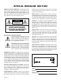
SPECIAL MESSAGE SECTION
PRODUCT SAFETY MARKINGS: Yamaha electronic prod-
ucts may have either labels similar to the graphics shown
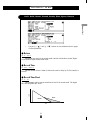
below or molded/stamped facsimiles of these graphics on the
enclosure. The explanation of these graphics appears on this
page. Please observe all cautions indicated on this page and
those indicated in the safety instruction section.
methods used to produce them, meet these goals. In keeping
with both the letter and the spirit of the law, we want you to
be aware of the following:
Battery Notice: This product MAY contain a small non-
rechargeable battery which (if applicable) is soldered in place.
The average life span of this type of battery is approximately
five years. When replacement becomes neccessary, contact a
qualified service representative to perform the replacement.
Warning: Do not attempt to recharge, disassemble, or incin-
erate this type of battery. Keep all batteries away from
children. Dispose of used batteries promptly and as regulated
by applicable laws. Note: In some areas, the servicer is
required by law to return the defective parts. However, you
do have the option of having the servicer dispose of these
parts for you.
Disposal Notice: Should this product become damaged be-
yond repair, or for some reason its useful life is considered
to be at an end, please observe all local, state, and federal
regulations that relate to the disposal of products that contain
lead, batteries, plastics, etc.
NOTICE: Service charges incurred due to lack of knowledge
relating to how a function or effect works (when the unit is
operating as designed) are not covered by the manufacturer’s
warranty, and are therefore the owners responsibility. Please
study this manual carefully and consult your dealer before
requesting service.
NAME PLATE LOCATION: The graphic below indicates
the location of the name plate. The model number, serial
number, power requirements, etc., are located on this plate.
You should record the model number, serial nunber, and the
date of purchase in the spaces provided below and retain this
manual as a permanent record of your purchase.
CAUTION: TO REDUCE THE RISK OF
ELECTRIC SHOCK, DO NOT REMOVE
COVER (OR BACK). NO USER-SERVICEABLE
PARTS INSIDE. REFER SERVICING TO
QUALIFIED SERVICE PERSONNEL
RISK OF ELECTRIC SHOCK
DO NOT OPEN
CAUTION
The exclamation point within the equilateral
triangle is intended to alert the user to the
presence of important operating and mainte-
nance (servicing) instructions in the litera-
ture accompanying the product.
The lightning flash with arrowhead symbol
within the equilateral triangle is intended to
alert the user to the presence of uninsulated
“dangerous voltage” within the product’s
enclosure that may be of sufficient magni-
tude to constitute a risk of electrical shock.
IMPORTANT NOTICE: All Yamaha electronic products are
tested and approvend by an independent safety testing labo-
ratory in order that you may be sure that when it is properly
installed and used in its normal and customary manner, all
foreseeable risks have been eliminated. DO NOT modify this
unit or commission others to do so unless specifically author-
ized by Yamaha. Product performance and/or safety standards
may be diminished. Claims filed under the expressed warranty
may be denied if the unit is/has been modified. Implied
warranties may also be affected.
SPECFICATIONS SUBJECT TO CHANGE: The informa-
tion contained in this manual is believed to be correct at the
time of printing. However, Yamaha reserves the right to
change or modify any of the specifications without notice or
obligation to update existing units.
ENVIRONMENTAL ISSUES: Yamaha strives to produce
products that are both user safe and environmentally friendly.
We sincerely believe that our products and the production
● Explanation of Graphical Symbols
92-469 q
Model
Serial No.
Purchase Date
R
L
OUTPUT
AC INLET
THRU OUT
MIDI
IN

IMPORTANT SAFETY INSTRUCTIONS
INFORMATION RELATING TO PERSONAL INJURY, ELECTRICAL SHOCK,
AND FIER HAZARD POSSIBILITIES HAS BEEN INCLUDED IN THIS LIST.
PLEASE KEEP THIS MANUAL
8. This product was NOT designed for use in wet/damp
locations and should not be used near water or exposed to
rain. Examples of wet/damp locations are; near a swim-
ming pool, spa, tub, sink, or wet basement.
9. This product should be used only with the components
supplied or; a cart, rack, or stand that is recommended by
the manufacturer. If a cart, rack, or stand is used, please
observe all safety markings and instructions that accom-
pany the accessory product.
10.The power supply cord (plug) should be disconnected
from the outlet when electronic products are to be left
unused for extended periods of time. Cords should also be
disconnected when there is a high probability of lightening
and/or electrical storm activity.
11.Care should be taken that objects do not fall and liquids
are not spilled into the enclosure through any openings
that may exist.
12.Electrical/electronic products should be serviced by a
qualified service person when:
a. The power supply cord has been damaged; or
b. Objects have fallen, been inserted, or liquids have been
spilled into the enclosure through openings; or
c. The product has been exposed to rain; or
d. The product does not operate, exhibits a marked change
in performance; or
e. The product has been dropped, or the enclosure of the
product has been damaged.
13.Do not attempt to service this product beyond that de-
scribed in the user-maintenance instructions. All other
servicing should be referred to qualified service personnel.
14.This product, either alone or in combination with an
amplifier and headphones or speaker/s, may be capable of
producing sound levels that could cause permanent hear-
ing loss. DO NOT operate for a long period of time at a
high volume level or at a level that is uncomfortable. If
you experience any hearing loss or ringing in the cars, you
should cousult an audiologist. IMPORTANT: The louder
the sound, the shorter the time period before damage
occurs.
15.Some Yamaha products may have benches and/or acces-
sory mounting fixtures that are either supplied as a part of
the product or as optional accessories. Some of these items
are designed to be dealer assembled or installed. Please
make sure that benches are stable and any optional fixtures
(where applicable) are well secured BEFORE using. Benches
supplied by Yamaha are designed for seating only. No
other uses are recommended.
WARNING — When using any electrical or electronic prod-
uct, basic precautions should always be followed. These
precautions include, but are not limited to, the following:
1. Read all Safety Instructions, Installation Instructions, Spe-
cial Message Section items, and any Assembly Instruc-
tions found in this manual BEFORE making any connec-
tions, including connection to the main supply.
2. Main Power Suplly Verifications: Yamaha products are
manufactured specifically for the supply voltage in the
area where they are to be sold. If you should move, or if
any doubt exists about the supply voltage in your area,
please contact your dealer for supply voltage verification
and (if applicable) instructions. The required supply volt-
age is printed on the name plate. For name plate location,
please refer to the graphic found in the Special Message
Section of this manual.
3. This product may be equipped with a polarized plug (one
blade wider than the other). If you are unable to insert the
plug into the outlet, turn the plug over and try again. If the
problem persists, contact electrician to have the obsolete
outlet replaced. Do NOT defeat the safety purpose of the
plug.
4. Some electronic products utilize external power supplies
or adapters. DO NOT connect this type of product to any
power supply or adapter other than one described in the
owners manual, on the name plate, or specifically recom-
mended by Yamaha.
5. WARNING: Do not place this product or any other objects
on the power cord or place it in a position where anyone
could walk on, trip over, or roll anything over power or
connecting cords of any kind. The use of an extension cord
is not recommended! If you must use an extension cord,
the minimume wire size for a 25' cord (or less) is 18 AWG.
NOTE: The smaller the AWG number, the larger the
current handling capacity. For longer extension cords,
consult a local electrician.
6. Ventilation: Electronic products, unless specifically de-
signed for enclosed installations, should be placed in
locations that do not interfere with proper ventilation. If
instructions for enclosed installations are not provided, it
must be assumed that unobstructed ventilation is required.
7. Temperature considerations: Electronic products should be
installed in locations that do not significantly contribute to
their operating temperature. Placement of this product
close to heat sources such as; radiators, heat registers and
other devices that produce heat should be avoided.
92-469-3

Owner’s Manual 2
Feature Reference
Virtual Acoustic Tone Generator

2
Feature Reference
Contents
■ 3: Feedback Delay . . . . . . . . . . . . . . . . . . . . . . 53
• Mono Delay . . . . . . . . . . . . . . . . . . . . . . . 53
• L,R Delay . . . . . . . . . . . . . . . . . . . . . . . . 55
• L,C,R Delay . . . . . . . . . . . . . . . . . . . . . . 57
■ 4:Reverberation . . . . . . . . . . . . . . . . . . . . . . . . 60
• Hall1, Hall2, Room1, Room2, Studio,
Plate, Space, Reverse . . . . . . . . . . . . . . . 61
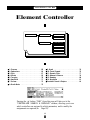
Element Controller . . . . . . . . . . . . . . . . . . . . . 64
■ 1: Pressure . . . . . . . . . . . . . . . . . . . . . . . . . . . . 65
■ 2: Embouchure . . . . . . . . . . . . . . . . . . . . . . . . 66
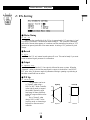
■ 3: Pitch . . . . . . . . . . . . . . . . . . . . . . . . . . . . . . . 67
■ 4: Vibrato . . . . . . . . . . . . . . . . . . . . . . . . . . . . . 69
■ 5: Tonguing . . . . . . . . . . . . . . . . . . . . . . . . . . . 70
■ 6: Amplitude . . . . . . . . . . . . . . . . . . . . . . . . . . 71
■ 7: Scream . . . . . . . . . . . . . . . . . . . . . . . . . . . . . 72
■ 8: Breath Noise . . . . . . . . . . . . . . . . . . . . . . . . 73
■ 9: Growl . . . . . . . . . . . . . . . . . . . . . . . . . . . . . . 74
■ 10: Throat Formant . . . . . . . . . . . . . . . . . . . . . 75
■ 11: Dynamic Filter . . . . . . . . . . . . . . . . . . . . . 77
■ 12; Harmonic Enhancer . . . . . . . . . . . . . . . . . 78
■ 13: Damping . . . . . . . . . . . . . . . . . . . . . . . . . . 80
■ 14: Absorption . . . . . . . . . . . . . . . . . . . . . . . . . 81
■ Controller Search & Replace . . . . . . . . . . . . . 82
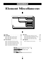
Element Miscellaneous . . . . . . . . . . . . . . . . . 84
■ 1: Setting . . . . . . . . . . . . . . . . . . . . . . . . . . . . . 85
■ 2: Breath Noise . . . . . . . . . . . . . . . . . . . . . . . . 86
• 2-1: Breath Noise Level Key Scaling . . 88
• 2-2: Breath Noise HPF Key Scaling . . . 89
• 2-3: Breath Noise LPF Key Scaling . . . . 90
■ 3: Throat Formant . . . . . . . . . . . . . . . . . . . . . . 91
• 3-1: Throat Formant Pitch Key Scaling . 93
• 3-2: Throat Formant Amount Key
Scaling . . . . . . . . . . . . . . . . . . . . . . . 94
• 3-3: Throat Formant Intensity Key
Scaling . . . . . . . . . . . . . . . . . . . . . . . 95
• 3-4: Throat Formant HPF Key Scaling . 96
• 3-5: Throat Formant LPF Key Scaling . 97
■ 4: Mixing . . . . . . . . . . . . . . . . . . . . . . . . . . . . . 98
• 4-1: Mixing Driver Output Key Scaling 100
• 4-2: Mixing Pipe/String Output Key
Scaling . . . . . . . . . . . . . . . . . . . . . . 101
About the Manuals . . . . . . . . . . . . . . . . . . . . . . 4
■ The Getting Started Manual . . . . . . . . . . . . . . . 4
■ The Feature Reference Manual (this manual) . 5
■ Conventions . . . . . . . . . . . . . . . . . . . . . . . . . . . . 5
General Operation
■ The Three Main Modes . . . . . . . . . . . . . . . . . . . 8
■ Finding Functions & Parameters . . . . . . . . . . . 9
■ Other Navigation Aids . . . . . . . . . . . . . . . . . . 11
■ Selecting & Editing Parameters . . . . . . . . . . . 12
Play Mode
■ The Main Play Mode Display . . . . . . . . . . . . . 14
■ Voice Selection . . . . . . . . . . . . . . . . . . . . . . . . 15
■ Controller Views . . . . . . . . . . . . . . . . . . . . . . . 17
■ Quick Editing In the Play Mode . . . . . . . . . . . 19
■ The Monitor Mode . . . . . . . . . . . . . . . . . . . . . 20
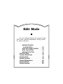
Edit Mode
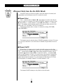
■ Element Selection In the Edit Mode . . . . . . . 22
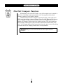
■ The Edit Compare Function . . . . . . . . . . . . . . 23
■ The Copy Function . . . . . . . . . . . . . . . . . . . . . 24
■ Storing Edited Data . . . . . . . . . . . . . . . . . . . . . 27
Initial Edit Page . . . . . . . . . . . . . . . . . . . . . . . . 30
Common Miscellanous . . . . . . . . . . . . . . . . . 34
■ 1: Setting . . . . . . . . . . . . . . . . . . . . . . . . . . . . . 35
■ 2: Controller . . . . . . . . . . . . . . . . . . . . . . . . . . 36
■ 3: Element Pitch . . . . . . . . . . . . . . . . . . . . . . . 37
■ 4: Element Level & Pan . . . . . . . . . . . . . . . . . 38
■ 5: Portamento . . . . . . . . . . . . . . . . . . . . . . . . . 40
■ 6: Micro Tuning . . . . . . . . . . . . . . . . . . . . . . . 42
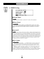
■ 7: Quick Edit Assign . . . . . . . . . . . . . . . . . . . . 43
Common Effect . . . . . . . . . . . . . . . . . . . . . . . . 44
■ 1: Setting . . . . . . . . . . . . . . . . . . . . . . . . . . . . . 45
■ 2: Modulation Effect . . . . . . . . . . . . . . . . . . . . 46
• Flanger . . . . . . . . . . . . . . . . . . . . . . . . . . . 47
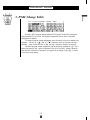
• Pitch Change . . . . . . . . . . . . . . . . . . . . . . 49
• Distortion . . . . . . . . . . . . . . . . . . . . . . . . . 51

3
Feature Reference
• 4-3: Mixing Tap Output Key Scaling . 102
• 4-4: Mixing Tap Location Key Scaling 103
■ 5: Amplitude . . . . . . . . . . . . . . . . . . . . . . . . . 104
• 5-1: Total Amplitude Level Key Scaling104
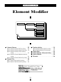
Element Modifier . . . . . . . . . . . . . . . . . . . . . 106
■ 1: Harmonic Enhancer . . . . . . . . . . . . . . . . . 107
•1-1: Harmonic Enhancer HPF Key
Scaling . . . . . . . . . . . . . . . . . . . . . . 110
•1-2: Harmonic Enhancer Overdrive Key
Scaling . . . . . . . . . . . . . . . . . . . . . . 111
• 1-3: Harmonic Enhancer Carrier Level
Key Scaling . . . . . . . . . . . . . . . . . . 112
• 1-4: Harmonic Enhancer Modulator
Index Key Scaling . . . . . . . . . . . . . 113
• 1-5: Harmonic Enhancer Balance Key
Scaling . . . . . . . . . . . . . . . . . . . . . . 114
■ 2: Dynamic Filter . . . . . . . . . . . . . . . . . . . . . 115
• 2-1: Dynamic Filter Cutoff Key Scaling 117
• 2-2: Dynamic Filter Resonance Key
Scaling . . . . . . . . . . . . . . . . . . . . . . 118
■ 3: Equalizer Auxiliary . . . . . . . . . . . . . . . . . . 119
• 3-1: Equalizer Auxiliary HPF Key
Scaling . . . . . . . . . . . . . . . . . . . . . . 120
• 3-2: Equalizer Auxiliary LPF Key
Scaling . . . . . . . . . . . . . . . . . . . . . . 121
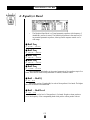
■ 4: Equalizer Band . . . . . . . . . . . . . . . . . . . . . 122
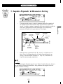
■ 5: Impulse Expander & Resonator Setting . . 123
■ 6: Impulse Expander . . . . . . . . . . . . . . . . . . . 125
■ 7: Resonator . . . . . . . . . . . . . . . . . . . . . . . . . . 126
Element Envelope . . . . . . . . . . . . . . . . . . . . . 128
■ 1: Pressure . . . . . . . . . . . . . . . . . . . . . . . . . . . 129
■ 2: Embouchure & Pitch . . . . . . . . . . . . . . . . . 130
• 2-1: Embouchure & Pitch Hold Time
Key Scaling . . . . . . . . . . . . . . . . . . 132
• 2-2: Embouchure & Pitch Initial Level
Key Scaling . . . . . . . . . . . . . . . . . . 133
• 2-3: Embouchure & Pitch Decay Rate
Key Scaling . . . . . . . . . . . . . . . . . . 134
■ 3: Vibrato . . . . . . . . . . . . . . . . . . . . . . . . . . . . 135
• 3-1: Vibrato Delay Time Key Scaling . 137
• 3-2: Vibrato Attack Rate Key Scaling . 138
• 3-3: Vibrato Depth Key Scaling . . . . . . 139
• 3-4: Vibrato Speed Key Scaling . . . . . . 140
■ 4: Growl . . . . . . . . . . . . . . . . . . . . . . . . . . . . . 141
• 4-1: Growl Speed Key Scaling . . . . . . . 142
■ 5: Amplitude & Filter . . . . . . . . . . . . . . . . . . 143
• 5-1: Amplitude & Filter Attack Rate
Key Scaling . . . . . . . . . . . . . . . . . . 146
• 5-2: Amplitude & Filter Attack 1 Level
Key Scaling . . . . . . . . . . . . . . . . . . 147
• 5-3: Amplitude & Filter Decay Rate
Key Scaling . . . . . . . . . . . . . . . . . . 148
• 5-4: Amplitude & Filter Sustain Level
Key Scaling . . . . . . . . . . . . . . . . . . 149
• 5-5: Amplitude & Filter Release Rate
Key Scaling . . . . . . . . . . . . . . . . . . 150
Utility Mode
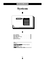
System . . . . . . . . . . . . . . . . . . . . . . . . . . . . . . 152
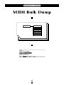
MIDI Bulk Dump . . . . . . . . . . . . . . . . . . . . . . 160
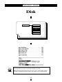
Disk . . . . . . . . . . . . . . . . . . . . . . . . . . . . . . . . . 162
Edit Recall . . . . . . . . . . . . . . . . . . . . . . . . . . . 172
Demo . . . . . . . . . . . . . . . . . . . . . . . . . . . . . . . 174
Appendix
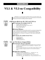
VL1 & VL1-m Compatibility . . . . . . . . . . . . 178
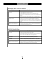
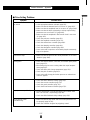
Troubleshooting . . . . . . . . . . . . . . . . . . . . . . 179
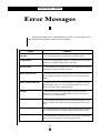
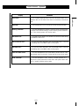
Error Messages . . . . . . . . . . . . . . . . . . . . . . . 182
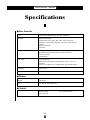
Specifications . . . . . . . . . . . . . . . . . . . . . . . . 184
Index . . . . . . . . . . . . . . . . . . . . . . . . . . . . . . . . 186

4
Feature Reference
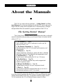
About the Manuals
The VL1-m comes with two manuals — Getting Started and Fea-
ture Reference. If you’re just starting out with the VL1-m we urge you to
begin with the Getting Started manual since it describes basic concepts
and procedures that are essential to proper operation of the VL1-m.
The Getting Started Manual
The Getting Started manual contains seven chapters that take you through
essential information and procedures you will need to know to become familiar
with your VL1-m:
1. VL1-m Basics [≥ Page 8]
Basic concepts you’ll need to understand in order to get the
most out of the VL1-m.
2. The Controls & Connectors [≥ Page 16]
Brief descriptions of the VL1-m controls and connectors, and
their functions.
3. Setting Up [≥ Page 22]
System connections, powering up, playing the demo, calibrating
the Breath Controller, and loading the pre-programmed voices.
4. Voice Selection [≥ Page 34]
Several ways to select and play the VL1-m’s 128 voices.
5. The Controllers [≥ Page 38]
The VL1-m controllers and how they can be assigned and
edited for optimum control.
6. Mixing & The Modifiers [≥ Page 48]
Customizing the sound to suit your own personal needs.
7. Effects [≥ Page 58]
An overview of the built-in digital effects that you can use to
add depth and ambience to the VL1-m sound.
We recommend that you go through the chapters in sequence and actually
try out the various operations described. Once you’ve gone through the entire
Getting Started manual in this way, you should be familiar enough with the
VL1-m to need only the VL1-m Feature Reference manual in future.

5
Feature Reference
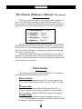
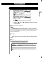
The Feature Reference Manual (this manual)
The Feature Reference manual is the “nuts and bolts” reference for
the VL1-m, individually describing its many functions in detail. The
Feature Reference manual is divided into five main sections, each describ-
ing the various functions within a particular VL1-m edit or utility mode.
1. General Operation [≥ Page 7]
2. Play Mode [≥ Page 13]
3. Edit Mode [≥ Page 21]
4. Utility Mode [≥ Page 151]
5. Appendix [≥ Page 177]
Once you have become familiar with the way the VL1-m works by
going through the Getting Started manual, you should only need to refer
to the Feature Reference manual from time to time to get details on func-
tions you’ve never used before, or refresh your memory about functions
that you don’t use very often.
Each section of the Feature Reference manual has its own table of
contents, so you should be able to locate any particular function quickly
and easily. Functions and references can also be located by referring to the
index at the back of the manual.
Conventions
The following conventions are used through the VL1-m manuals to
avoid confusion and make the text easier to read.
Buttons & Controls
Button and control names used on the VL1-m panel appear in the
text in capital letters within a border: “the P button”, for exam-
ple.
Parameter Names
Parameter names and other labels which appear on the VL1-m
display are printed in the courier typeface for easier identifica-
tion: for example, “adjust the “Balance” parameter as required”.
Parameter Ranges
An ellipsis is used to indicate a range of parameter values: e.g. “0
… 127”. This minimizes the confusion sometimes caused by the use
of a hyphen or dash for this purpose.

6
Feature Reference

General Operation
The VL1-m makes operation as easy as possible
by providing a consistent, logical control interface via
which its many functions and parameters can be
accessed and edited. Once you become familiar with
the system, operation should be smooth, efficient, and
easy.
● The Three Main Modes . . . . . . . . . . . . . 8
● Finding Functions & Parameters . . . . . 9
● Other Navigation Aids . . . . . . . . . . . . . 11
● Selecting & Editing Parameters . . . . . 12

8
Feature Reference
●
General Operation
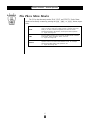
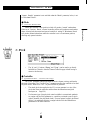
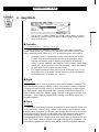
The Three Main Modes
The VL1-m has three main modes: PLAY, EDIT, and UTILITY. Each of these
modes can be directly accessed by pressing the P, E, or U button, respec-
tively.
The PLAY mode is the one you use to select and play the VL1-m
voices. The PLAY mode also includes several “Controller Views” that
allow you to check controller assignments, the status of several
important performance parameters, and the quick edit assignments.
≥
Pages 13 through 20.
All voice editing functions are accessed via the EDIT mode: controller
assignments, mixing, modifiers, effects, and more.
≥
Pages 21 through 150.
The UTILITY mode includes a range of functions that affect overall
operation of the VL1-m rather than individual voices. For example:
master tuning, MIDI settings, disk operations, etc.
≥
Pages 151 through 175.
PLAY
EDIT
UTILITY

9
Feature Reference
●
General Operation
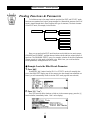
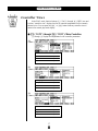
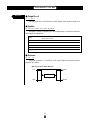
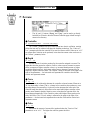
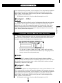
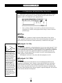
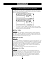
Finding Functions & Parameters
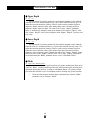
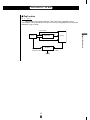
To facilitate access to the many functions provided, the EDIT and UTILITY mode
functions are organized into logical groups arranged in a hierarchical structure (the PLAY
mode is simple enough that it doesn’t require this type of structure). The basic structure
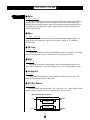
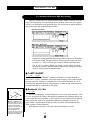
of the EDIT mode, for example, looks like this:
EDIT MODE
ELEMENT
EFFECT
CONTROLLER
MODIFIER
ENVELOPE
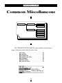
COMMON
MISCELLANEOUS
MISCELLANEOUS
Here you can see that the EDIT mode functions are divided into two main groups:
COMMON and ELEMENT, and that these are further sub-divided into related groups of
functions. The COMMON EFFECT group, for example, includes all the effect parameters
(flange, reverb, etc.) that apply to the entire voice. Here’s how you would access the
reverb parameters, starting from the PLAY mode:
●
Example: Locate the Effect Reverb Parameters
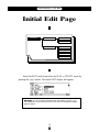
1. Press E
Pressing the E button from the PLAY or UTILITY mode will normally take
you to the initial EDIT display page (if the current voice has already been edited but not
stored, you will automatically return to the last EDIT mode page that was selected).
2. Press ¡ (“Com”)
Since you want the effect functions, which are in the common group, press the ¡
function button (immediately below “Com” on the display).

10
Feature Reference
●
General Operation
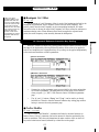
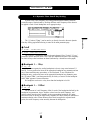
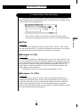
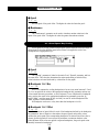
3. If Necessary, Press ™ (“Efct”)
If the miscellaneous directory is showing (in this case “Misc” above the ¡ button
will be highlighted), press the ™ button below “Efct” on the display to select the
effect directory.
4. Move the Cursor To “4:Reverberation” and Press [
Use the cursor buttons (or the - and = buttons, or the data dial)
to move the cursor to “4:Reverberation” and press the [ button. This will
take you to the first page of reverb parameters.
NOTES ■ Notice that the top line of the display shows the “path” to the current
level or function: “
EDIT/COM/EFFECT/REVERBERATION
”.
This example illustrates the two methods used to move downward through the EDIT
mode levels: 1) press the appropriate function button and 2) move the cursor to the
desired selection and press [.
From any point within the structure you can move upward toward the topmost level
(in this case the initial EDIT mode display) by pressing the ] button. You move up
one level each time the ] button is pressed, until the topmost level is reached.
To exit from the EDIT mode itself you must press either the P or U
button, depending on the mode you want to switch to. You can exit from the EDIT mode
at any level by doing this, and you will be returned automatically to the same display
page the next time you press the E button as long as the voice being edited is not
stored or a new voices is not selected.

11
Feature Reference
●
General Operation
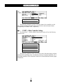
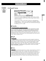
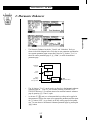
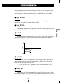
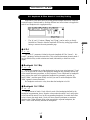
Other Navigation Aids
In addition to the standard procedures described in the previous section, the VL1-m
sometimes provides additional help in moving between related functions via the function
buttons.
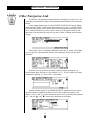
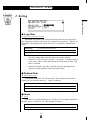
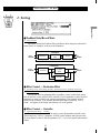
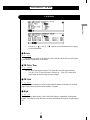
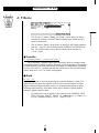
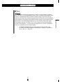
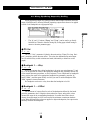
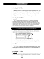
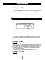
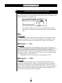
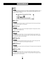
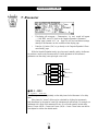
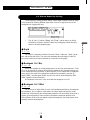
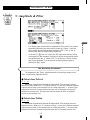
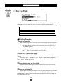
In this example display page from the ELEMENT CONTROLLER group, “Bpag”
(back page) and “Fpag” (forward page) appear above the § and ¶ function buttons.
In this case these buttons can be used to move forward and backward through the entire
list of controller functions so you don’t have to move up to the function directory and
then down to the next function every time you want to select a different element control-
ler page.
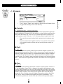
Also note the “Para” (Parameter) abbreviation above the • button. This enables
you to go directly to the parameters related to the current page: in this case the vibrato
parameters.
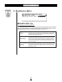
From here you can go back to the vibrato controller page by pressing the •
function button again (note that it is now labelled “Ctrl”), or to the vibrato key scaling
parameters by pressing ¶, below “KSC” on the display.
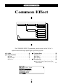
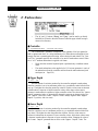
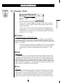
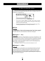
Another variation appears in the COMMON EFFECT parameter displays. In most
cases the number of parameters available for each effect exceeds the capacity of the
display, so the ¡ and ™ function buttons are used to scroll up and down the parameter
list — note the “>” and “<” arrows above the buttons in the display.

12
Feature Reference
●
General Operation
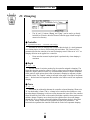
Selecting & Editing Parameters
Once you’ve locate the display page that contains the parameter(s) you want to edit,
simply use the cursor buttons to move the cursor to the parameter, and then use the data
dial or the = and - buttons to set the parameter as required. The data dial is ideal
for quickly covering a large range of settings, while the = and - buttons are best
for small stepwise changes.

Play Mode
The primary function of the PLAY mode is to
allow you to select and play voices. The VL1-m play
mode additionally offers a range of controller views
that let you check controller assignments, and simple
“quick edit” capability. Select the PLAY mode from
either the EDIT or UTILITY mode by pressing the
P button.
● The Main Play Mode Display . . . . . . . 14
● Voice Selection . . . . . . . . . . . . . . . . . . 15
● Controller Views . . . . . . . . . . . . . . . . . 17
● Quick Editing In the Play Mode . . . . . 19
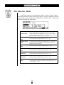
● The Monitor Mode . . . . . . . . . . . . . . . . 20

14
Feature Reference
●
Play Mode
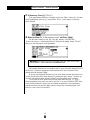
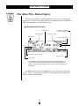
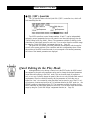
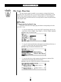
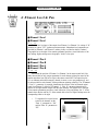
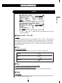
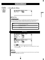
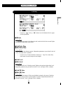
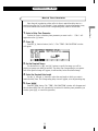
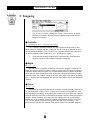
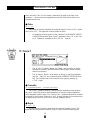
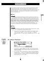
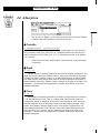
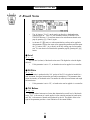
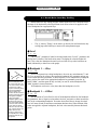
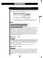
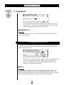
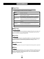
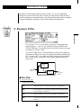
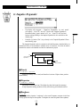
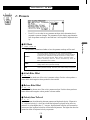
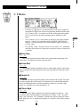
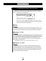
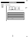
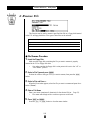
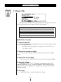
The Main Play Mode Display
When you select the PLAY mode by pressing the P button, the main PLAY
mode display will appear. This display includes a considerable amount of information in
addition to the name of the currently selected voice.
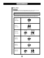
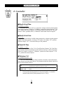
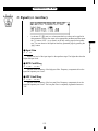
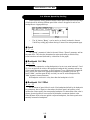
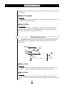
■ The Normal Voice Display
Voice number.
Element E1 and E2 names.
Voice mode.
Voice name.
Play mode.
Reverb on or off.
Stereo output mode.
Effects in use.
Pressure, Amplitude,
or D.Filter Controller *
* If controllers are assigned to both Pressure and Amplitude, the con-
troller with the highest amplitude depth value will be displayed. If
neither is assigned, the Dynamic Filter controller will be displayed (if
assigned).
The abbreviations in the section separated by a line at the bottom of the display
(“Cnt1”, “Cnt2”, etc) indicate the functions of the corresponding function buttons
below the display (described below).

15
Feature Reference
●
Play Mode
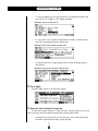
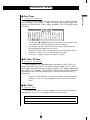
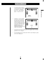
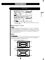
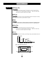
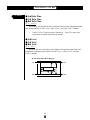
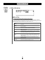
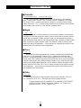
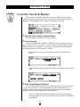
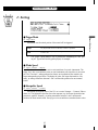
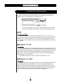
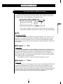
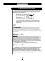
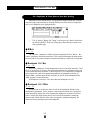
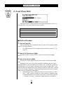
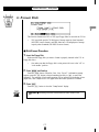
Voice Selection
The VL1-m’s 128 voices are organized into 8 banks — “A” through “H” — of 16
voices each (8 x 16 = 128). These can be selected in sequence by using either the data
dial or the = and - buttons. Note that the voice number which appears on the
play mode display includes both the voice bank/number (“A01” through “A16”, “B01”
through “B16”, etc.) and the absolute voice number in parentheses following the bank/
number (“001” through “128”).
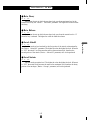
DEC INC
● = and - Buttons
These are best for small, step-wise changes —
e.g. selecting adjacent voice numbers, or
numbers that are only a few steps away. Press
the = or - key briefly to decrement or
increment the voice number by one, or hold
either key for continuous decrementing or
incrementing in the corresponding direction.
The = and - buttons also have a
largestep function which allows you to skip
ahead or backward in increments of 16: press
either the = or - button while holding
the other button. The bank will switch auto-
matically if you cross a bank voice-number
boundary.
● Data Dial
The data dial provides a fast, efficient way to
cover a broad range of voice numbers when,
for example, you’re looking for a voice but
don’t know the voice number. Simply rotate
the data dial clockwise for higher voice
numbers or counter-clockwise for lower voice
numbers while watching the display. The
banks are automatically switched when neces-
sary as the voice numbers are changed.

16
Feature Reference
●
Play Mode
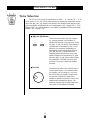
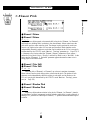
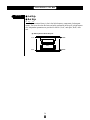
●
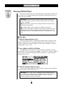
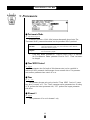
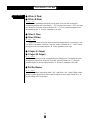
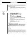
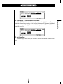
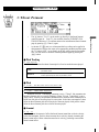
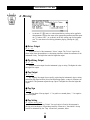
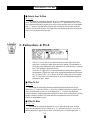
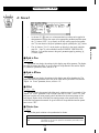
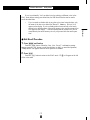
Using the Voice Directory
The VL1-m also features a voice directory display that can be more convenient than
the normal voice display in some situations. To switch to the voice directory display,
press the • button — located directly below “Dir” on the display. The directory
display shows all 16 voices in the current bank. Voices can be selected using either the
data dial or = and - buttons as described above — the cursor will move to the
selected voice. You can also use the cursor keys to move the cursor to the next voice to
be selected (the voice is not actually selected in this case — the cursor will flash), then
press the [ key to actually select the specified voice. This method lets you switch
directly to the specified voice without having to go through all others in between
To return to the normal voice display press the ] or P button.
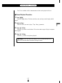
●
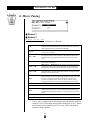
The Sound Function
You can check the sound of the current voice in the PLAY mode directly from the
VL1-m panel: press the
ENTER/SOUND
key. The pitch played is C4. When a voice is
played in this way all 14 controller parameters (“Pressure” through “Absorption”) are
turned off.
Seite wird geladen ...
Seite wird geladen ...
Seite wird geladen ...
Seite wird geladen ...
Seite wird geladen ...
Seite wird geladen ...
Seite wird geladen ...
Seite wird geladen ...
Seite wird geladen ...
Seite wird geladen ...
Seite wird geladen ...
Seite wird geladen ...
Seite wird geladen ...
Seite wird geladen ...
Seite wird geladen ...
Seite wird geladen ...
Seite wird geladen ...
Seite wird geladen ...
Seite wird geladen ...
Seite wird geladen ...
Seite wird geladen ...
Seite wird geladen ...
Seite wird geladen ...
Seite wird geladen ...
Seite wird geladen ...
Seite wird geladen ...
Seite wird geladen ...
Seite wird geladen ...
Seite wird geladen ...
Seite wird geladen ...
Seite wird geladen ...
Seite wird geladen ...
Seite wird geladen ...
Seite wird geladen ...
Seite wird geladen ...
Seite wird geladen ...
Seite wird geladen ...
Seite wird geladen ...
Seite wird geladen ...
Seite wird geladen ...
Seite wird geladen ...
Seite wird geladen ...
Seite wird geladen ...
Seite wird geladen ...
Seite wird geladen ...
Seite wird geladen ...
Seite wird geladen ...
Seite wird geladen ...
Seite wird geladen ...
Seite wird geladen ...
Seite wird geladen ...
Seite wird geladen ...
Seite wird geladen ...
Seite wird geladen ...
Seite wird geladen ...
Seite wird geladen ...
Seite wird geladen ...
Seite wird geladen ...
Seite wird geladen ...
Seite wird geladen ...
Seite wird geladen ...
Seite wird geladen ...
Seite wird geladen ...
Seite wird geladen ...
Seite wird geladen ...
Seite wird geladen ...
Seite wird geladen ...
Seite wird geladen ...
Seite wird geladen ...
Seite wird geladen ...
Seite wird geladen ...
Seite wird geladen ...
Seite wird geladen ...
Seite wird geladen ...
Seite wird geladen ...
Seite wird geladen ...
Seite wird geladen ...
Seite wird geladen ...
Seite wird geladen ...
Seite wird geladen ...
Seite wird geladen ...
Seite wird geladen ...
Seite wird geladen ...
Seite wird geladen ...
Seite wird geladen ...
Seite wird geladen ...
Seite wird geladen ...
Seite wird geladen ...
Seite wird geladen ...
Seite wird geladen ...
Seite wird geladen ...
Seite wird geladen ...
Seite wird geladen ...
Seite wird geladen ...
Seite wird geladen ...
Seite wird geladen ...
Seite wird geladen ...
Seite wird geladen ...
Seite wird geladen ...
Seite wird geladen ...
Seite wird geladen ...
Seite wird geladen ...
Seite wird geladen ...
Seite wird geladen ...
Seite wird geladen ...
Seite wird geladen ...
Seite wird geladen ...
Seite wird geladen ...
Seite wird geladen ...
Seite wird geladen ...
Seite wird geladen ...
Seite wird geladen ...
Seite wird geladen ...
Seite wird geladen ...
Seite wird geladen ...
Seite wird geladen ...
Seite wird geladen ...
Seite wird geladen ...
Seite wird geladen ...
Seite wird geladen ...
Seite wird geladen ...
Seite wird geladen ...
Seite wird geladen ...
Seite wird geladen ...
Seite wird geladen ...
Seite wird geladen ...
Seite wird geladen ...
Seite wird geladen ...
Seite wird geladen ...
Seite wird geladen ...
Seite wird geladen ...
Seite wird geladen ...
Seite wird geladen ...
Seite wird geladen ...
Seite wird geladen ...
Seite wird geladen ...
Seite wird geladen ...
Seite wird geladen ...
Seite wird geladen ...
Seite wird geladen ...
Seite wird geladen ...
Seite wird geladen ...
Seite wird geladen ...
Seite wird geladen ...
Seite wird geladen ...
Seite wird geladen ...
Seite wird geladen ...
Seite wird geladen ...
Seite wird geladen ...
Seite wird geladen ...
Seite wird geladen ...
Seite wird geladen ...
Seite wird geladen ...
Seite wird geladen ...
Seite wird geladen ...
Seite wird geladen ...
Seite wird geladen ...
Seite wird geladen ...
Seite wird geladen ...
Seite wird geladen ...
Seite wird geladen ...
Seite wird geladen ...
Seite wird geladen ...
Seite wird geladen ...
Seite wird geladen ...
Seite wird geladen ...
Seite wird geladen ...
Seite wird geladen ...
Seite wird geladen ...
Seite wird geladen ...
Seite wird geladen ...
Seite wird geladen ...
Seite wird geladen ...
Seite wird geladen ...
Seite wird geladen ...
-
 1
1
-
 2
2
-
 3
3
-
 4
4
-
 5
5
-
 6
6
-
 7
7
-
 8
8
-
 9
9
-
 10
10
-
 11
11
-
 12
12
-
 13
13
-
 14
14
-
 15
15
-
 16
16
-
 17
17
-
 18
18
-
 19
19
-
 20
20
-
 21
21
-
 22
22
-
 23
23
-
 24
24
-
 25
25
-
 26
26
-
 27
27
-
 28
28
-
 29
29
-
 30
30
-
 31
31
-
 32
32
-
 33
33
-
 34
34
-
 35
35
-
 36
36
-
 37
37
-
 38
38
-
 39
39
-
 40
40
-
 41
41
-
 42
42
-
 43
43
-
 44
44
-
 45
45
-
 46
46
-
 47
47
-
 48
48
-
 49
49
-
 50
50
-
 51
51
-
 52
52
-
 53
53
-
 54
54
-
 55
55
-
 56
56
-
 57
57
-
 58
58
-
 59
59
-
 60
60
-
 61
61
-
 62
62
-
 63
63
-
 64
64
-
 65
65
-
 66
66
-
 67
67
-
 68
68
-
 69
69
-
 70
70
-
 71
71
-
 72
72
-
 73
73
-
 74
74
-
 75
75
-
 76
76
-
 77
77
-
 78
78
-
 79
79
-
 80
80
-
 81
81
-
 82
82
-
 83
83
-
 84
84
-
 85
85
-
 86
86
-
 87
87
-
 88
88
-
 89
89
-
 90
90
-
 91
91
-
 92
92
-
 93
93
-
 94
94
-
 95
95
-
 96
96
-
 97
97
-
 98
98
-
 99
99
-
 100
100
-
 101
101
-
 102
102
-
 103
103
-
 104
104
-
 105
105
-
 106
106
-
 107
107
-
 108
108
-
 109
109
-
 110
110
-
 111
111
-
 112
112
-
 113
113
-
 114
114
-
 115
115
-
 116
116
-
 117
117
-
 118
118
-
 119
119
-
 120
120
-
 121
121
-
 122
122
-
 123
123
-
 124
124
-
 125
125
-
 126
126
-
 127
127
-
 128
128
-
 129
129
-
 130
130
-
 131
131
-
 132
132
-
 133
133
-
 134
134
-
 135
135
-
 136
136
-
 137
137
-
 138
138
-
 139
139
-
 140
140
-
 141
141
-
 142
142
-
 143
143
-
 144
144
-
 145
145
-
 146
146
-
 147
147
-
 148
148
-
 149
149
-
 150
150
-
 151
151
-
 152
152
-
 153
153
-
 154
154
-
 155
155
-
 156
156
-
 157
157
-
 158
158
-
 159
159
-
 160
160
-
 161
161
-
 162
162
-
 163
163
-
 164
164
-
 165
165
-
 166
166
-
 167
167
-
 168
168
-
 169
169
-
 170
170
-
 171
171
-
 172
172
-
 173
173
-
 174
174
-
 175
175
-
 176
176
-
 177
177
-
 178
178
-
 179
179
-
 180
180
-
 181
181
-
 182
182
-
 183
183
-
 184
184
-
 185
185
-
 186
186
-
 187
187
-
 188
188
-
 189
189
-
 190
190
-
 191
191
-
 192
192
-
 193
193
-
 194
194
-
 195
195


Yamaha VL1 Bedienungsanleitung
- Kategorie
- Digitale Klaviere
- Typ
- Bedienungsanleitung
- Dieses Handbuch eignet sich auch für
in anderen Sprachen
- English: Yamaha VL1 Owner's manual
- français: Yamaha VL1 Le manuel du propriétaire
- español: Yamaha VL1 El manual del propietario
- italiano: Yamaha VL1 Manuale del proprietario
- русский: Yamaha VL1 Инструкция по применению
- Nederlands: Yamaha VL1 de handleiding
- português: Yamaha VL1 Manual do proprietário
- dansk: Yamaha VL1 Brugervejledning
- polski: Yamaha VL1 Instrukcja obsługi
- čeština: Yamaha VL1 Návod k obsluze
- svenska: Yamaha VL1 Bruksanvisning
- Türkçe: Yamaha VL1 El kitabı
- suomi: Yamaha VL1 Omistajan opas
- română: Yamaha VL1 Manualul proprietarului