Yamaha RX-V861 Bedienungsanleitung
- Kategorie
- AV-Receiver
- Typ
- Bedienungsanleitung

YAMAHA ELECTRONICS CORPORATION, USA
6660 ORANGETHORPE AVE., BUENA PARK, CALIF. 90620, U.S.A.
YAMAHA CANADA MUSIC LTD.
135 MILNER AVE., SCARBOROUGH, ONTARIO M1S 3R1, CANADA
YAMAHA ELECTRONIK EUROPA G.m.b.H.
SIEMENSSTR. 22-34, 25462 RELLINGEN BEI HAMBURG, GERMANY
YAMAHA ELECTRONIQUE FRANCE S.A.
RUE AMBROISE CROIZAT BP70 CROISSY-BEAUBOURG 77312 MARNE-LA-VALLEE CEDEX02, FRANCE
YAMAHA ELECTRONICS (UK) LTD.
YAMAHA HOUSE, 200 RICKMANSWORTH ROAD WATFORD, HERTS WD18 7GQ, ENGLAND
YAMAHA SCANDINAVIA A.B.
J A WETTERGRENS GATA 1, BOX 30053, 400 43 VÄSTRA FRÖLUNDA, SWEDEN
YAMAHA MUSIC AUSTRALIA PTY, LTD.
17-33 MARKET ST., SOUTH MELBOURNE, 3205 VIC., AUSTRALIA
©
2007 All rights reserved.
RX-V861
Printed in Malaysia WJ70140
RX-V861
AV Receiver
Ampli-tuner audio-vidéo
OWNER’S MANUAL
MODE D’EMPLOI
BEDIENUNGSANLEITUNG
BRUKSANVISNING
GEBRUIKSAANWIJZING
ИНСТРУКЦИЯ ПО ЭКСПЛУАТАЦИИ
G
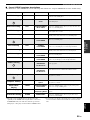
HUGHES NETWORK SYSTEMS
0069
HYPSON 0099
ITT 0068, 0131, 0267
ITV 0064, 0305
IMPERIAL 0027
INTERFUNK 0108
JVC 0068, 0072, 0094
JENSEN 0068
KEC 0064, 0305
KLH 0099
KAISUI 0099
KENWOOD 0068, 0094
KODAK 0062, 0064
KOLIN 0068, 0070
KORPEL 0099
LG 0064, 0069, 0072,
0507
LXI 0064
LENCO 0305
LEYCO 0099
LLOYD’S 0027
LOEWE 0064, 0108, 1589
LOGIK 0099, 0267
LUXOR 0070, 0075, 0131
M ELECTRONIC
0027
MEI 0062
MGA 0070, 0267
MGN TECHNOLOGY
0267
MTC 0027, 0267
MAGNASONIC
1305
MAGNAVOX 0027, 0062, 0066,
0108, 1808
MAGNIN 0267
MANESTH 0072, 0099
MARANTZ 0062, 0108
MARTA 0064
MATSUI 0375, 0379
MATSUSHITA
0062
MEDION 0375
MEMOREX 0027, 0062, 0064,
0066, 0074, 0075,
0131, 0267, 0334,
0375, 1264
MEMPHIS 0099
METZ 0064, 0374, 1589
MINOLTA 0069
MITSUBISHI 0068, 0070, 0094,
0108, 0834
MOTOROLA 0062, 0075
MULTITECH 0027, 0099
MURPHY 0027
MYRYAD 0108
NAD 0131
NEC 0062, 0064, 0068,
0075, 0094, 0131
NATIONAL 0253
NECKERMANN 0108
NESCO 0099
NEWAVE 0064
NIKKO 0064
NOBLEX 0267
NOKIA 0068, 0131, 0267
NORDMENDE 0068, 0347
OCEANIC 0027, 0068
OKANO 0342, 0375
OLYMPUS 0062, 0253
OPTIMUS 0064, 0075, 0131,
0459
ORION 0211, 0375, 0379,
1506
OSAKI 0027, 0064, 0099
OTTO VERSAND 0108
PALLADIUM 0064, 0068, 0099
PANASONIC 0062, 0252, 0253,
0643, 1062, 1589
PATHE MARCONI 0068
PENNEY 0062, 0064, 0069,
0267, 1062, 1264
PENTAX 0069
PERDIO 0027
PHILCO 0062
PHILIPS 0062, 0108, 0645,
1108, 1208
PHONOLA 0108
PILOT 0064
PIONEER 0069, 0094, 0108
POLK AUDIO 0108
PROFITRONIC 0267
PROLINE 0027
PROSCAN 0087, 1087
PROTEC 0099
PULSAR 0066
PYE 0108
QUASAR 0062, 1062
QUELLE 0108
RCA 0062, 0069, 0087,
0267, 0834, 1062,
1087
RADIOSHACK 0027
RADIOLA 0108
RADIX 0064
RANDEX 0064
REALISTIC 0027, 0062, 0064,
0074, 0075, 0131
REOC 0375
REPLAYTV 0641, 0643
REX 0068
ROADSTAR 0064, 0099, 0267,
0305
RUNCO 0066
SBR 0108
SEG 0267
SEI 0108
STS 0069
SABA 0068, 0347
SALORA 0070
SAMPO 0064, 0075
SAMSUNG 0072, 0267, 0459
SANKY 0066, 0075
SANSUI 0027, 0068, 0094,
1506
SANYO 0074, 0131, 0267
SAVILLE 0379
SCHAUB LORENZ 0027, 0068,
0131
SCHNEIDER 0027, 0099, 0108
SCOTT 0070, 0072, 0211
SEARS 0027, 0062, 0064,
0069, 0074, 0131,
1264
SELECO 0068
SEMP 0072
SHARP 0075, 0834
SHINTOM 0099, 0131
SIEMENS 0064, 0108, 0131
SILVA 0064
SINGER 0072, 0099
SINUDYNE 0108
SONIC BLUE 0641, 0643
SONTEC 0064
SONY 0027, 0059, 0060,
0062, 0663, 1259
SUNKAI 0375
SUNSTAR 0027
SUNTRONIC 0027
SYLVANIA 0027, 0062, 0108,
0070, 1808
SYMPHONIC 0027
TMK 0267
TANDY 0027, 0131
TASHIKO 0027, 0064
TATUNG 0027, 0068, 0072,
0094, 0108
TEAC 0027, 0068, 0305,
0334, 0669
TECHNICS 0062, 0253
TECO 0062, 0064, 0068,
0075
TEKNIKA 0027, 0062, 0064
TELEAVIA 0068
TELEFUNKEN 0068, 0347
TENOSAL 00 99
TENSAI 0027
THOMAS 0027
THOMSON 0068, 0087, 0094,
0347
THORN 0068, 0131
TIVO 0645, 0663
TOSHIBA 0068, 0070, 0072,
0094, 0108, 0872
TOTEVISION 0064, 0267
UHER 0267
UNITECH 0267
UNIVERSUM 0027, 0064, 0108,
0267
VECTOR 0072
VICTOR 0068, 0094
VIDEO CONCEPTS 0072
VIDEOMAGIC 0064
VIDEOSONIC 0267
VILLAIN 0027
WARDS 0027, 0062, 0069,
0074, 0075, 0087,
0099, 0108, 0267
WHITE WESTINGHOUSE
0099
XR-1000 0027, 0062, 0099
YAMAHA 0068
YAMISHI 0099
YOKAN 0099
YOKO 0267
ZENITH 0027, 0060, 0066,
1506
RX-V861_G-cv.fm Page 1 Monday, February 5, 2007 3:00 PM

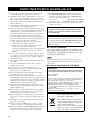
CAUTION: READ THIS BEFORE OPERATING YOUR UNIT.
En
1 To assure the finest performance, please read this manual
carefully. Keep it in a safe place for future reference.
2 Install this sound system in a well ventilated, cool, dry, clean
place – away from direct sunlight, heat sources, vibration,
dust, moisture, and/or cold. Allow ventilation space of at least
30 cm on the top, 20 cm on the left and right, and 20 cm on
the back of this unit.
3 Locate this unit away from other electrical appliances, motors,
or transformers to avoid humming sounds.
4 Do not expose this unit to sudden temperature changes from
cold to hot, and do not locate this unit in an environment with
high humidity (i.e. a room with a humidifier) to prevent
condensation inside this unit, which may cause an electrical
shock, fire, damage to this unit, and/or personal injury.
5 Avoid installing this unit where foreign objects may fall onto
this unit and/or this unit may be exposed to liquid dripping or
splashing. On the top of this unit, do not place:
– other components, as they may cause damage and/or
discoloration on the surface of this unit.
– burning objects (i.e. candles), as they may cause fire,
damage to this unit, and/or personal injury.
– containers with liquid in them, as they may fall and liquid
may cause electrical shock to the user and/or damage to
this unit.
6 Do not cover this unit with a newspaper, tablecloth, curtain,
etc. in order not to obstruct heat radiation. If the temperature
inside this unit rises, it may cause fire, damage to this unit,
and/or personal injury.
7 Do not plug in this unit to a wall outlet until all connections
are complete.
8 Do not operate this unit upside-down. It may overheat,
possibly causing damage.
9 Do not use force on switches, knobs and/or cords.
10 When disconnecting the power cable from the wall outlet,
grasp the plug; do not pull the cable.
11 Do not clean this unit with chemical solvents; this might
damage the finish. Use a clean, dry cloth.
12 Only voltage specified on this unit must be used. Using this
unit with a higher voltage than specified is dangerous and may
cause fire, damage to this unit, and/or personal injury. Yamaha
will not be held responsible for any damage resulting from use
of this unit with a voltage other than specified.
13 To prevent damage by lightning, keep the power cord and
outdoor antennas disconnected from a wall outlet or the unit
during a lightning storm.
14 Do not attempt to modify or fix this unit. Contact qualified
Yamaha service personnel when any service is needed. The
cabinet should never be opened for any reasons.
15 When not planning to use this unit for long periods of time
(i.e. vacation), disconnect the AC power plug from the wall
outlet.
16 Install this unit near the AC outlet and where the AC power
plug can be reached easily.
17 Be sure to read the “Troubleshooting” section on common
operating errors before concluding that this unit is faulty.
18 Before moving this unit, press MASTER ON/OFF to release it
outward to the OFF position to turn off this unit, and then
disconnect the AC power plug from the AC wall outlet.
19 VOLTAGE SELECTOR (Asia and General models only)
The VOLTAGE SELECTOR on the rear panel of this unit
must be set for your local main voltage BEFORE plugging
into the AC wall outlet. Voltages are:
Asia model ............................ 220/230–240 V AC, 50/60 Hz
General model ........ 110/120/220/230–240 V AC, 50/60 Hz
20 The batteries shall not be exposed to excessive heat such as
sunshine, fire or like.
■ For U.K. customers
If the socket outlets in the home are not suitable for the
plug supplied with this appliance, it should be cut off and
an appropriate 3 pin plug fitted. For details, refer to the
instructions described below.
The plug severed from the mains lead must be destroyed, as a
plug with bared flexible cord is hazardous if engaged in a live
socket outlet.
■ Special Instructions for U.K. Model
Caution: Read this before operating your unit.
WARNING
TO REDUCE THE RISK OF FIRE OR ELECTRIC
SHOCK, DO NOT EXPOSE THIS UNIT TO RAIN
OR MOISTURE.
As long as this unit is connected to the AC wall outlet,
it is not disconnected from the AC power source even
if you turn off this unit by MASTER ON/OFF. In this
state, this unit is designed to consume a very small
quantity of power.
Note
IMPORTANT
THE WIRES IN MAINS LEAD ARE COLOURED IN
ACCORDANCE WITH THE FOLLOWING CODE:
Blue: NEUTRAL
Brown: LIVE
As the colours of the wires in the mains lead of this apparatus
may not correspond with the coloured markings identifying
the terminals in your plug, proceed as follows:
The wire which is coloured BLUE must be connected to the
terminal which is marked with the letter N or coloured
BLACK. The wire which is coloured BROWN must be
connected to the terminal which is marked with the letter L or
coloured RED.
Making sure that neither core is connected to the earth
terminal of the three pin plug.
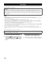
This symbol mark is according to the
EU directive 2002/96/EC.
This symbol mark means that electrical
and electronic equipment, at their end-
of-life, should be disposed of separately
from your household waste.
Please act according to your local rules
and do not dispose of your old products
with your normal household waste.

1 En
PREPARATIONINTRODUCTION
BASIC
OPERATION
ADVANCED
OPERATION
ADDITIONAL
INFORMATION
APPENDIX
English
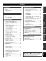
Notice ....................................................................... 2
Features ................................................................... 3
Supplied accessories .................................................. 3
Getting started ........................................................ 4
Quick start guide .................................................... 5
Connections........................................................... 11
Optimizing the speaker setting
for your listening room .................................... 28
Using AUTO SETUP .............................................. 28
Selecting the SCENE templates........................... 33
Selecting the desired SCENE template.................... 33
Creating your original SCENE templates................ 36
Playback ................................................................ 37
Basic procedure ....................................................... 37
Selecting the MULTI CH INPUT component......... 38
Selecting the front speaker set ................................. 38
Selecting audio input jacks
(AUDIO SELECT).............................................. 39
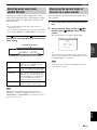
Displaying the current status of this unit
on a video monitor............................................... 39
Using your headphones............................................ 40
Muting the audio output........................................... 40
Playing video sources in the background
of an audio source................................................ 40
Displaying the input source information ................. 40
Using the sleep timer ............................................... 41
Sound field programs.......................................... 42
Selecting sound field programs ............................... 42
Sound field program descriptions............................ 42
Enjoying unprocessed input sources
(Straight decoding mode) .................................... 47
Using audio features ............................................. 48
Enjoying pure hi-fi sound ........................................ 48
Adjusting the tonal quality....................................... 48
Adjusting the speaker level...................................... 48
Enjoying multi-channel sources in 2-channel stereo
..... 49
Selecting the night listening mode........................... 49
FM/AM tuning ...................................................... 50
Automatic tuning ..................................................... 50
Manual tuning.......................................................... 50
Automatic preset tuning........................................... 51
Manual preset tuning ............................................... 51
Selecting preset stations........................................... 52
Exchanging preset stations ...................................... 52
Radio Data System tuning
(Europe model only)......................................... 53
Displaying the Radio Data System information ...... 53
Selecting the Radio Data System program type
(PTY SEEK mode).............................................. 54
Using the enhanced other networks
(EON) data service .............................................. 55
Using iPod™.......................................................... 56
Controlling iPod™................................................... 56
Recording .............................................................. 58
Advanced sound configurations...........................59
Changing sound field parameter settings................. 59
Selecting decoders ................................................... 64
Customizing this unit (MANUAL SETUP).........67
Using SET MENU................................................... 69
1 SOUND MENU.................................................... 70
2 INPUT MENU...................................................... 76
3 OPTION MENU................................................... 79
Remote control features........................................83
Using the remote control for the SCENE feature .... 83
Controlling this unit, a TV, or other components.... 84
Setting remote control codes ................................... 86
Programming codes from other remote controls ..... 88
Changing source names in the display window....... 89
Macro programming features .................................. 90
Clearing configurations ........................................... 93
Using multi-zone configuration............................96
Connecting Zone 2................................................... 96
Controlling Zone 2................................................... 97
Advanced setup......................................................99
Using the advanced setup ........................................ 99
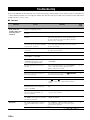
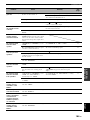
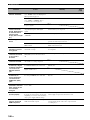
Troubleshooting...................................................104
Resetting the system............................................111
Glossary................................................................112
Sound field program information......................114
Parametric equalizer information .....................115
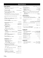
Specifications .......................................................116
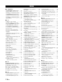
Index.....................................................................118
(at the end of this manual)
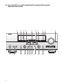
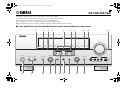
Front panel................................................................i
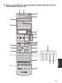
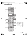
Remote control ....................................................... ii
List of remote control codes ................................. iii
Contents
INTRODUCTION
PREPARATION
BASIC OPERATION
ADVANCED OPERATION
ADDITIONAL INFORMATION
APPENDIX
“
1
SPEAKERS” or “
A
DVD” (example) indicates the name
of the parts on the front panel or the remote control. Refer to
the attached sheet or the pages at the end of this manual for
the information about each position of the parts.

NOTICE
2 En
Manufactured under license from Dolby Laboratories.
“Dolby”, “Pro Logic”, and the double-D symbol are trademarks
of Dolby Laboratories.
DTS-ES | NEO:6 | 96/24. Product “DTS” and “DTS-ES | NEO:6”
are registered trademarks of DTS, Inc.
“96/24” is a trademark of DTS, Inc.
“iPod” is a trademark of Apple Inc., registered in the U.S. and
other countries.
“HDMI”, the “HDMI” logo and “High-Definition Multimedia
Interface” are trademarks or registered trademarks of HDMI
Licensing LLC.
“SILENT CINEMA” is a trademark of YAMAHA
CORPORATION.
Notice
About this manual
• y indicates a tip for your operation.
• Some operations can be performed by using either the
buttons on the front panel or the ones on the remote
control. In case the button names differ between the front
panel and the remote control, the button name on the
remote control is given in parentheses.
• This manual is printed prior to production. Design and
specifications are subject to change in part as a result of
improvements, etc. In case of differences between the
manual and product, the product has priority.
•“
1
SPEAKERS” or “
A
DVD” (example) indicates the
name of the parts on the front panel or the remote control.
Refer to the attached sheet or the pages at the end of this
manual for the information about each position of the
parts.
•
The symbol “☞ ” with page number(s) indicates the
corresponding reference page(s).
iPod
TM

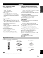
Features
3 En
INTRODUCTION
English
Built-in 7-channel power amplifier
◆ Minimum RMS output power
(20 Hz to 20 kHz, 0.06% THD, 8 Ω)
Front: 105 W + 105 W
Center: 105 W
Surround: 105 W + 105 W
Surround back: 105 W + 105 W
SCENE function
◆ 17 preset SCENE templates for various situations
◆ 4 original SCENE templates for customizing capability
◆ Controlling Yamaha SCENE control signal support
component (some models only) working with the SCENE
function
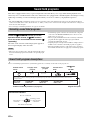
Sound field programs
◆ Proprietary Yamaha technology for the creation of sound
fields
◆ Compressed Music Enhancer mode to improve the sound
quality of compression artifacts (such as the MP3 format) to
that of a high-quality stereo
◆ Dolby Digital/Dolby Digital EX decoder
◆ DTS/DTS-ES Matrix, Discrete, DTS Neo:6,
DTS 96/24 decoder
◆ Dolby Pro Logic/Dolby Pro Logic II/Dolby Pro Logic IIx
decoder
◆ Virtual CINEMA DSP
◆ SILENT CINEMA
Sophisticated FM/AM tuner
◆ 40-station random and direct preset tuning
◆ Automatic preset tuning
◆ Preset station shifting capability (preset editing)
◆ Radio Data System capability (Europe model only)
HDMI (High-Definition Multimedia Interface)
◆ HDMI interface for standard, enhanced or high-definition
video (includes 1080p video signal transmission) as well as
multi-channel digital audio based on HDMI version 1.2a
◆ Analog video to HDMI digital video up-conversion
(composite video ↔ S-video ↔ component video → HDMI
digital video) capability for monitor out
◆ Analog video deinterlacing and/or up-scaling (480i (NTSC)/
576i (PAL) → 480p/576p → 720p or 1080i)
iPod controlling capability
◆ DOCK terminal to connect a Yamaha iPod universal dock
(such as the YDS-10, sold separately), which supports iPod
(Click and Wheel), iPod nano, and iPod mini
◆ Playback information displaying capability
◆ Battery charging capability
Other features
◆ YPAO (Yamaha Parametric Room Acoustic Optimizer) for
automatic speaker setup
◆ 192-kHz/24-bit D/A converter
◆ OSD (on-screen display) menus that allow you to optimize
this unit to suit your individual audiovisual system
◆ 5.1 or 7.1-channel additional input jacks for discrete multi-
channel input
◆ S-video signal input/output capability
◆ Component video input/output capability includes
(3 COMPONENT VIDEO INs and 1 MONITOR OUT)
◆ Digital video signal conversion (composite video ↔ S-video
→ component video) capability for monitor out
◆ Optical and coaxial digital audio signal jacks
◆ Pure Direct mode for pure hi-fi sound for all sources
◆ Cinema and music night listening modes
◆ Remote control with preset remote control codes capability
◆ Zone 2 custom installation facility
◆ Zone switching capability between the main zone and Zone 2
using ZONE CONTROL
◆ Bi-amplification connection capability
◆ Sleep timer
Check that you received all of the following parts.
The form of the supplied accessories varies depending on the models.
Features
Supplied accessories
Note
V
-
AUX/DOCK
–
+
+
––
+
ENTER
DISPLAY
AUDIO
MENU
TITLE
TV MUTE
TV INPUT
MUTE
4
3
2
ENT
+
10
0
9
5
1
AV
TV
1234
7
6
8
RETURN
ON
OFF
CLEAR
LEARN
RENAME
MACRO
REC
FREQ/TEXT EON MODE-PTY SEEK-START
VOLUME
STRAIGHT
PURE DIRECT
A/B/C/D/E
PRESET/CH
SET MENU
BAND
LEVEL
SLEEP
STEREO
SUR. DECODE
NIGHT
CLASSICAL
LIVE/CLUB
ENTERTAIN
ENHANCER
MOVIE
TV
SOURCE
AMP
SELECT
DTV/CBL
VCR
DVR
DVD
TUNER
MD/CD-R
CD
PHONO
MULTI CH IN
POWER
POWER
SCENE
POWER
STANDBY
TV VOL TV CH
Remote control
Batteries (4)
(AAA, R03, UM-4)
AM loop antenna
Optimizer microphone
Indoor FM antenna

GETTING STARTED
4 En
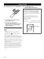
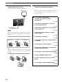
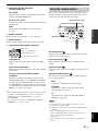
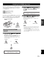
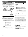
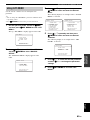
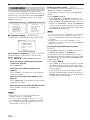
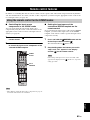
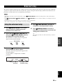
■ Installing batteries in the remote control
1 Press the part and slide the battery
compartment cover off.
2 Insert the four supplied batteries
(AAA, R03, UM-4) according to the polarity
markings (+ and –) on the inside of the
battery compartment.
3 Slide the cover back until it snaps into place.
• Change all of the batteries if you notice the following
conditions:
– the operation range of the remote control decreases.
– the transmit indicator (
X
) does not flash or its light becomes
dim.
• Do not use an old battery together with a new one.
• Do not use different types of batteries (such as alkaline and
manganese batteries) together. Read the packaging carefully as
these different types of batteries may have the same shape and
color.
• If the batteries have leaked, dispose of them immediately. Avoid
touching the leaked material or letting it come into contact with
clothing, etc. Clean the battery compartment thoroughly before
installing new batteries.
• Do not throw away batteries with general house waste; dispose
of them correctly in accordance with your local regulations.
• If the remote control is without batteries for more than 2
minutes, or if exhausted batteries remain in the remote control,
the contents of the memory may be cleared. When the memory
is cleared, insert new batteries, set up the remote control code
and program any acquired functions that may have been
cleared.
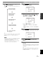
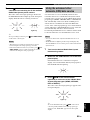
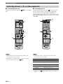
■ VOLTAGE SELECTOR
(Asia and General models only)
Getting started
Notes
1
3
2
Caution
The VOLTAGE SELECTOR on the rear panel of this
unit must be set for your local voltage BEFORE
plugging the power cable into the AC wall outlet.
Improper setting of the VOLTAGE SELECTOR may
cause damage to this unit and create a potential fire
hazard.
Rotate the VOLTAGE SELECTOR clockwise or
counterclockwise to the correct position using a
straight slot screwdriver.
Voltages are as follows:
Asia model
....................................220/230–240 V AC, 50/60 Hz
General model
......................110/120/220/230–240 V AC, 50/60 Hz
230-
240V
VOLTAGE
SELECTOR
Voltage indication

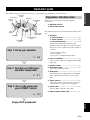
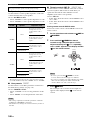
Quick start guide
5 En
INTRODUCTION
English
The following steps describe the easiest way to enjoy DVD movie playback in your home theater.
In these steps, you need the following supplied
accessories.
❏ AM loop antenna
❏ Indoor FM antenna
The following items are not included in the package of this
unit.
❏ Speakers
❏ Front speakers .................................... 2
❏ Center speaker ................................... 1
❏ Surround speakers ............................. 4
Select magnetically shielded speakers. The
minimum required speakers are two front speakers.
The priority of the requirement of other speakers is
as follows:
1. Two surround speakers
2. Center speaker
3. One (or two) surround back speaker(s)
❏ Active subwoofer .................................... 1
Select an active subwoofer equipped with an RCA
input jack.
❏ Speaker cables ........................................ 7
❏ Subwoofer cable ..................................... 1
Select a monaural RCA cable.
❏ DVD player ............................................... 1
Select DVD player equipped with coaxial digital
audio output jack and composite video output
jack.
❏ Video monitor........................................... 1
Select a TV monitor, video monitor or projector
equipped with a composite video input jack.
❏ Video cable .............................................. 1
Select an RCA composite video cable.
❏ Digital coaxial audio cable ..................... 1
Quick start guide
Front right
speaker
Subwoofer
Surround back
right speaker
Surround left
speaker
Front left
speaker
Surround back left
speaker
Surround right
speaker
Center
speaker
Video monitor
DVD player
Enjoy DVD playback!
Step 1: Set up your speakers
☞
P. 6
Step 2: Connect your DVD player
and other components
Step 3: Turn on the power and
press SCENE 1 button
☞
P. 7
☞
P. 9
Preparation: Check the items

Quick start guide
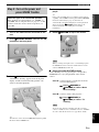
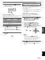
6 En
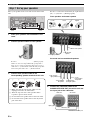
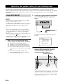
Place your speakers in the room and connect them to this
unit.
1 Place your speakers and subwoofer in the
room.
2 Connect speaker cables to each speaker.
Be sure to connect the “+” (red) and “–” (black) properly.
Cables are colored or shaped differently, perhaps with a
stripe, groove or ridge. Connect the striped (grooved, etc.)
cable to the “+” (red) terminals of this unit and your speaker.
Connect the plain cable to the “–” (black) terminals.
3 Connect each speaker cable to the
corresponding speaker terminal of this unit.
1 Make sure that this unit and the subwoofer are
unplugged from the AC wall outlets.
2 Twist the exposed wires of the speaker cables
together to prevent short circuits.
3 Do not let the bare speaker wires touch each other.
4 Do not let the bare speaker wires touch any metal
part of this unit.
Be sure to connect the left channel (L), right channel
(R), “+” (red) and “–” (black) properly.
Front speakers and center speaker
Surround and surround back speakers
4 Connect the subwoofer cable to the
SUBWOOFER PRE OUT jack of this unit and
the input jack of the subwoofer.
Step 1: Set up your speakers
A B
C
DOCK
DIGITAL OUTPUT
PHONO CD
MD/
DVD
DTV/CBL
DTV/CBL
DVR
DVD
DVR
DVD
IN OUT IN OUT
DTV/CBL
DVR
VCR
MONITOR
OUT
MONITOR OUT
CD-R
(PLAY)
OUT OUTIN
VCR SB(8CH)
FRONT(6CH)
SINGLE
CENTER CENTER
S VIDEO
VIDEO
OUT
SURROUND
SUBWOOFER
FRONT
SURROUND
SUR. BACK
SUBWOOFER
AUDIO
MULTI CH INPUT
ZONE 2
PRE OUT
OUTININ
(REC)
GND
MD/CD-R
MD/CD-R
DVD
DVD
DTV/CBL
OPTICAL
COAXIAL
CD
DVD
HDMI
OUT
DTV
/CBL
DIGITAL INPUT
OPTICAL
1
2
3
4
5
6
FRONT B/ZONE2/
FRONT A
CENTER
SURROUND
PRESENCE
EXTRA SP
ANTENNA
TRIGGER
COMPONENT VIDEO VIDEO
SPEAKERS
OUT
AM
REMOTE
+12V
15mA MAX.
IN
OUT
SURROUND BACK/
BI-AMP
SINGLE
AC OUTLETS
FM
75
UNBAL.
GND
L
R
L
R
L
R
L
R
L L
R R
IN1
IN2
YP
B
P
R
YP
B
P
R
12 3 4
4
To the front left
speaker
Front right speaker
To the center speaker
Loosen Insert Tighten
To the surround
right speaker
To the
surround back
left speaker
To the surround
left speaker
To the surround
back right speaker
SUBWOOFER PRE OUT jack
Input jack
AV receiverSubwoofer
Subwoofer cable

Quick start guide
7 En
INTRODUCTION
English
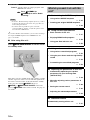
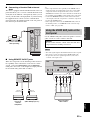
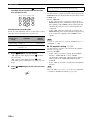
1 Connect the digital coaxial audio cable to the
digital coaxial audio output jack of your DVD
player and the DVD DIGITAL INPUT COAXIAL
jack of this unit.
2 Connect the video cable to the composite
video output jack of your DVD player and
DVD VIDEO jack of this unit.
3 Connect the video cable to the VIDEO
MONITOR OUT jack of this unit and the video
input jack of your video monitor.
Step 2: Connect your DVD player
and other components
A B
C
DOCK
DIGITAL OUTPUT
PHONO CD
MD/
DVD
DTV/CBL
DTV/CBL
DVR
DVD
DVR
DVD
IN OUT IN OUT
DTV/CBL
DVR
VCR
MONITOR
OUT
MONITOR OUT
CD-R
(PLAY)
OUT OUTIN
VCR SB(8CH)
FRONT(6CH)
SINGLE
CENTER CENTER
S VIDEO
VIDEO
OUT
SURROUND
SUBWOOFER
FRONT
SURROUND
SUR. BACK
SUBWOOFER
AUDIO
MULTI CH INPUT
ZONE 2
PRE OUT
OUTININ
(REC)
GND
MD/CD-R
MD/CD-R
DVD
DVD
DTV/CBL
OPTICAL
COAXIAL
CD
DVD
HDMI
OUT
DTV
/CBL
DIGITAL INPUT
OPTICAL
1
2
3
4
5
6
FRONT B/ZONE2/
FRONT A
CENTER
SURROUND
PRESENCE
EXTRA SP
ANTENNA
TRIGGER
COMPONENT VIDEO VIDEO
SPEAKERS
OUT
AM
REMOTE
+12V
15mA MAX.
IN
OUT
SURROUND BACK/
BI-AMP
SINGLE
AC OUTLETS
FM
75
UNBAL.
GND
L
R
L
R
L
R
L
R
L L
R R
IN1
IN2
YP
B
P
R
YP
B
P
R
Make sure that this unit and the DVD
player are unplugged from the AC
wall outlets.
Digital coaxial
audio output
jack
Digital coaxial audio
cable
DVD DIGITAL INPUT
COAXIAL jack
DVD player
AV receiver
Composite video
output jack
Video cable
DVD VIDEO jack
DVD player
AV receiver
Video monitor
AV receiver
Video cable
VIDEO MONITOR OUT jack
Video
input jack

Quick start guide
8 En
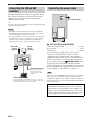
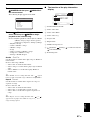
4 Connect the supplied AM loop antenna and
indoor FM antenna to this unit.
See page 24 for the connection information.
The types of the supplied indoor FM antenna and the FM
antenna terminal of this unit are different depending on the
models.
Connecting the wire of the AM loop antenna
y
The wire of the AM loop antenna does not have any polarity
and you can connect either end of the wire to AM or GND
terminal.
Assembling the supplied AM loop antenna
5 Connect the power plug of this unit and other
components into the AC wall outlet.
y
This unit is equipped with AC OUTLET(S) for the power
supply of the other components (except Korea model). See
page 24 for details.
Note
Indoor FM antenna
AM loop antenna
Open the lever
Insert
Close the lever
■ For further connections
• Using the other kind of speaker
combinations
☞ P. 12
• Connecting a video monitor via various
ways of the connection
☞ P. 18
• Connecting a DVD player via various ways
of the connection
☞ P. 19
• Connecting a DVD recorder or a digital
video recorder
☞ P. 20
• Connecting a set-top box
☞ P. 20
• Connecting a CD player, an MD recorder or
a turntable
☞ P. 21
• Connecting an external amplifier
☞ P. 22
• Connecting a DVD player via analog multi-
channel audio connection
☞ P. 22
• Connecting a Yamaha iPod universal dock
☞ P. 23
• Using the REMOTE IN/OUT jacks
☞ P. 23
• Using the VIDEO AUX jacks on the front
panel
☞ P. 23
• Connecting an outdoor FM/AM antenna
☞ P. 24

Quick start guide
9 En
INTRODUCTION
English
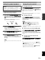
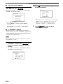
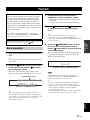
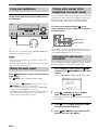
1 Turn on the video monitor connected to this
unit.
2 Press
B
MASTER ON/OFF inward to the ON
position on the front panel.
3 Press
F
SCENE1 button.
“DVD Movie Viewing” appears in the front panel
display, and this unit automatically optimize own
status for the DVD playback.
y
The indicator on the selected SCENE button lights up while
this unit is in the SCENE mode.
4 Start playback of the desired DVD on your
player.
y
If the connected DVD player is a Yamaha product and has
capability of the SCENE control signals with the REMOTE
OUT jack of this unit (see page 23), this unit can
automatically activate the DVD player and start playback
when you press the
F
SCENE1 button. Refer to the
instruction manual of the DVD player for further
information.
5 Rotate
0
VOLUME to adjust the volume.
When you change the input source or sound field program,
the SCENE mode is deactivated, and the indicator on the
selected SCENE button turns off.
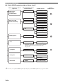
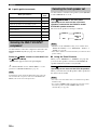
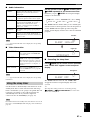
■ Using the other SCENE buttons
In the following cases, try pressing the corresponding
SCENE button to enjoy the playback of the desired
sources.
Case A: “I want to listen to a music disc from the
connected DVD player...”
Press
F
SCENE2 (or
A
SCENE2) to select “Music
Disc Listening”.
Case B: “I want to watch a TV program...”
Press
F
SCENE3 (or
A
SCENE3) to select “TV
Viewing”.
To use the “TV Viewing” template (Case B), you must
connect a satellite receiver, a cable TV receiver or an HDTV
decoder to this unit in advance. See page 20 for details.
Step 3: Turn on the power and
press SCENE 1 button
Check the type of the connected speakers.
If the speakers are 6 ohm speakers, set “SP IMP.” to
“6Ω MIN” before using this unit (see page 25). 4 ohm
speakers can be also used as the front speakers (see
page 100).
Note
Note

Quick start guide
10 En
Case C: “I want to listen to a music program of the
FM/AM radio station...”
Press
F
SCENE4 (or
A
SCENE4) to select “Radio
Listening”.
• To use the “Radio Listening” template (Case C), you have
to tune into the desired radio station. See pages 50 to 52
for the tuning information.
• To achieve the best possible reception, orient the
connected AM loop antenna, or adjust the position of the
end of the indoor FM antenna.
y
If you cannot find the desired situation, you can select and change
the assigned SCENE template for the SCENE buttons. See
page 33 for details.
■ After using this unit...
Press
A
MAIN ZONE ON/OFF to set this unit to
the standby mode.
This unit is set to the standby mode and consumes a small
amount of power in order to receive infrared signals from
the remote control. To turn on this unit from the standby
mode, press the desired
F
SCENE buttons (or
A
SCENE) or
A
MAIN ZONE ON/OFF on the front
panel (or
I
POWER on the remote control). See page 25
for details.
Notes
What do you want to do with this
unit?
■ Customizing the SCENE templates
• Using various SCENE templates
☞ P. 33
• Creating your original SCENE templates
☞ P. 36
■ Using various input sources
• Basic controls of this unit
☞ P. 37
• Enjoying FM/AM radio programs
☞ P. 50
• Using your iPod with this unit
☞ P. 56
■ Using various sound features
• Using various sound field programs
☞ P. 42
• Using the pure direct mode for high fidelity
sound
☞ P. 48
• Customizing the sound field programs
☞ P. 59
■ Adjusting the parameters of this unit
• Automatically optimizing the speaker
parameters for your listening room
(AUTO SETUP)
☞ P. 28
• Manually adjusting various parameters of
this unit
☞ P. 69
• Setting the remote control
☞ P. 83
• Adjusting the advanced parameters
☞ P. 99
■ Additional feature
Automatically turning off this unit
☞ P. 41

CONNECTIONS
11 En
PREPARATION
English
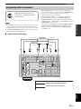
Connections
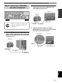
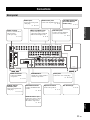
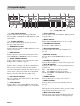
Rear panel
A B
C
DOCK
DIGITAL OUTPUT
PHONO CD
MD/
DVD
DTV/CBL
DTV/CBL
DVR
DVD
DVR
DVD
IN OUT IN OUT
DTV/CBL
DVR
VCR
MONITOR
OUT
MONITOR OUT
CD-R
(PLAY)
OUT OUTIN
VCR SB(8CH)
FRONT(6CH)
SINGLE
CENTER CENTER
S VIDEO
VIDEO
OUT
SURROUND
SUBWOOFER
FRONT
SURROUND
SUR. BACK
SUBWOOFER
AUDIO
MULTI CH INPUT
ZONE 2
PRE OUT
OUTININ
(REC)
GND
MD/CD-R
MD/CD-R
DVD
DVD
DTV/CBL
OPTICAL
COAXIAL
CD
DVD
HDMI
OUT
DTV
/CBL
DIGITAL INPUT
OPTICAL
1
2
3
4
5
6
FRONT B/ZONE2/
FRONT A
CENTER
SURROUND
PRESENCE
EXTRA SP
ANTENNA
TRIGGER
COMPONENT VIDEO VIDEO
SPEAKERS
OUT
AM
REMOTE
+12V
15mA MAX.
IN
OUT
SURROUND BACK/
BI-AMP
SINGLE
AC OUTLETS
FM
75
UNBAL.
GND
L
R
L
R
L
R
L
R
L L
R R
IN1
IN2
YP
B
P
R
YP
B
P
R
DOCK terminal
Connect a Yamaha iPod
universal dock
(sold separately).
☞ P. 23
AUDIO jacks
Connect the analog audio
cable plugs.
☞ P. 18-21
MULTI CH INPUT jacks
Connect the input source
component equipped with the
multi-channel output jacks.
☞ P. 22
ZONE 2 OUT jacks
Connect the amplifier in Zone 2.
☞ P. 96
PRE OUT jacks
Connect external amplifiers
and an active subwoofer.
☞ P. 22
VOLTAGE SELECTOR
(Asia and General
models only)
☞ P. 4
HDMI connectors
Connect the HDMI
components.
☞ P. 16
TRIGGER OUT
Outputs the control signals to
external components.
REMOTE IN/OUT jacks
Connect the remote control
input and output jacks of
the Yamaha components.
☞ P. 23
Speaker terminals
Connect the speakers.
☞ P. 13
Video jacks
Connect the video cable plugs.
☞ P. 18-20
AC OUTLET(S)
☞ P. 24
ANTENNA terminals
Connect the FM and AM
antenna.
☞ P. 24
DIGITAL INPUT/
OUTPUT jacks
Connect the digital audio
cable plugs.
☞ P. 19-21

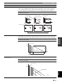
12 En
Connections
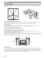
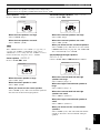
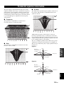
The speaker layout below shows the speaker setting we recommend. You can use it to enjoy CINEMA DSP and multi-
channel audio sources.
Front left and right speakers (FL and FR)
The front speakers are used for the main source sound plus effect sounds. Place these speakers at an equal distance from the
ideal listening position. The distance of each speaker from each side of the video monitor should be the same.
Center speaker (C)
The center speaker is for the center channel sounds (dialog, vocals, etc.). If for some reason it is not practical to use a
center speaker, you can do without it. Best results, however, are obtained with the full system.
Surround left and right speakers (SL and SR)
The surround speakers are used for effect and surround sounds.
Surround back left and right speakers (SBL and SBR)
The surround back speakers supplement the surround speakers and provide more realistic front-to-back transitions.
Presence left and right speakers (PL and PR)
The presence speakers supplement the sound from the front speakers with extra ambient effects produced by the sound field
programs (see page 42). To use the presence speakers, connect the speakers to EXTRA SP terminals and then set “EXTRA
SP ASSIGN” to “PRESENCE” (see pages 29 and 70).
Subwoofer (SW)
The use of a subwoofer with a built-in amplifier, such as the Yamaha Active Servo Processing Subwoofer System, is
effective not only for reinforcing bass frequencies from any or all channels, but also for high fidelity sound reproduction
of the LFE (low-frequency effect) channel included in Dolby Digital and DTS sources. The position of the subwoofer is
not so critical, because low bass sounds are not highly directional. But it is better to place the subwoofer near the front
speakers. Turn it slightly toward the center of the room to reduce wall reflections.
Placing speakers
60˚
30˚
PL
PR
SBR
SBL
FL
FR
C
SL
SR
SR
80˚
SL
30 cm (12 in) or more
SW
FR
PR
PL
FL
SBR
SBL
SL
SR
C
1.8 m (6 ft)
FR
PRPL
C
FL
1.8 m (6 ft)
0.5 to 1 m (1 to 3 ft) 0.5 to 1 m (1 to 3 ft)
1.8 m (6 ft)

13 En
Connections
PREPARATION
English
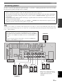
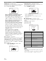
Be sure to connect the left channel (L), right channel (R), “+” (red) and “–” (black) properly. If the connections are faulty,
this unit cannot reproduce the input sources accurately.
A speaker cord is actually a pair of insulated cables running side by side. Cables are colored or shaped differently, perhaps with a stripe,
groove or ridge. Connect the striped (grooved, etc.) cable to the “+” (red) terminals of this unit and your speaker. Connect the plain cable
to the “–” (black) terminals.
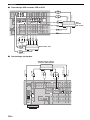
Connecting speakers
Caution
• Before connecting the speakers, make sure that this unit is turned off (see page 25).
• Do not let the bare speaker wires touch each other or let them touch any metal part of this unit. This could damage
this unit and/or the speakers. If the speaker wires are short-circuited, “CHECK SP WIRES” appears in the front
panel display.
• Use the magnetically shielded speakers. If this type of speaker still creates interference with the monitor, place the
speakers away from the monitor.
• If you are to use 6 ohm speakers, be sure to set “SP IMP.” to “6Ω MIN” before using this unit (see page 25). 4 ohm
speakers can be also used as the front speakers (see page 100).
Note
SUBWOOFER
PRE OUT
FRONT B/ZONE2/
FRONT A
CENTER
SURROUND
PRESENCE
EXTRA SP
SPEAKERS
SURROUND BACK/
BI-AMP
SINGLE
L
R
L
R
L L
R R
Front speakers
(FRONT A)
Surround speakers
Subwoofer
Right
Center speaker
Surround back speakers
When you use a single surround back
speaker, connect the speaker to the left
SURROUND BACK terminal
(SINGLE).
Left
Left
Left
Right
Right
EXTRA SP terminals
Connect the alternative front speaker system (FRONT B), presence speakers or
Zone 2 speakers. To select the function of the speakers connected to the EXTRA
SP terminals, set the “EXTRA SP ASSIGN” parameter in “SOUND MENU” (see
page 70).
y
You can also select the function of the speakers connected to the EXTRA SP
terminals in “AUTO SETUP” (see page 29).

14 En
Connections
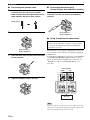
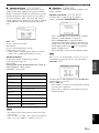
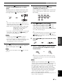
■ Connecting the speaker cable
1 Remove approximately 10 mm (0.4 in) of
insulation from the end of each speaker
cable and then twist the exposed wires of the
cable together to prevent short circuits.
2 Loosen the knob.
3 Insert one bare wire into the hole on the side
of each terminal.
4 Tighten the knob to secure the wire.
■ Connecting the banana plug
(except Europe, Asia and Korea models)
Tighten the knob and then insert the banana plug
connector into the end of the corresponding
terminal.
■ Using bi-amplification connections
This unit allows you to make bi-amplification connections
to one speaker system. Check if your speakers support bi-
amplification.
To make the bi-amplification connections, use the FRONT
and SURROUND BACK/BI-AMP terminals as shown
below. To activate the bi-amplification connections, set
“BI-AMP” to “ON” in “ADVANCED SETUP” (see
page 102).
When you make the conventional connection, make sure that the
shorting bars are put into the terminals appropriately. Refer to the
instruction manuals of the speakers for details.
10 mm (0.4 in)
Red: positive (+)
Black: negative (–)
Caution
Remove the shorting bars or bridges of your speakers
to separate the LPF (low pass filter) and HPF (high
pass filter) crossovers.
Note
Red: positive (+)
Black: negative (–)
FRONT A
SURROUND BACK/
BI-AMP
SINGLE
L
R
L
R
This unit
Left
Right
Front speakers

15 En
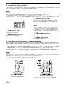
Connections
PREPARATION
English
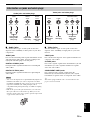
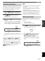
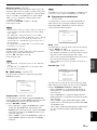
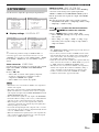
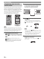
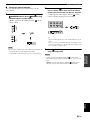
■ Audio jacks
This unit has three types of audio jacks. Connection
depends on the availability of audio jacks on your other
components.
AUDIO jacks
For conventional analog audio signals transmitted via left
and right analog audio cables. Connect red plugs to the
right jacks and white plugs to the left jacks.
DIGITAL COAXIAL jacks
For digital audio signals transmitted via coaxial digital
audio cables.
DIGITAL OPTICAL jacks
For digital audio signals transmitted via optical digital
audio cables.
• You can use the digital jacks to input PCM, Dolby Digital and
DTS bitstreams. When you connect components to both the
COAXIAL and OPTICAL jacks, priority is given to the signals
input at the COAXIAL jack. All digital input jacks are
compatible with digital signals with up to 96 kHz of sampling
frequency.
• Pull out the cap from the optical jack before you connect the
fiber optic cable. Do not discard the cap. When you are not
using the optical jack, be sure to put the cap back in place. This
cap protects the jack from dust.
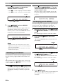
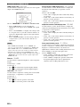
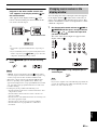
■ Video jacks
This unit has three types of video jacks. Connection
depends on the availability of input jacks on your video
monitor.
VIDEO jacks
For conventional composite video signals transmitted via
composite video cables.
S VIDEO jacks
For S-video signals, separated into the luminance (Y) and
chrominance (C) video signals transmitted on separate
wires of S-video cables.
COMPONENT VIDEO jacks
For component video signals, separated into the
luminance (Y) and chrominance (P
B, PR) video signals
transmitted on separate wires of component video cables.
y
This unit is equipped with the video conversion function. See
pages 17 and 79 for details.
Information on jacks and cable plugs
Notes
COAXIAL
DIGITAL
AUDIO
OPTICAL
DIGITAL
R
L
C
O
R
L
Left and right
analog audio
cable plugs
Optical
digital
audio cable
plug
Coaxial
digital audio
cable plug
Audio jacks and cable plugs
(Red)(White) (Orange)
VIDEO S VIDEO
COMPONENT VIDEO
Y
R
P
B
P
PB
Y
P
R
S
V
Composite
video cable
plug
S-video
cable plug
Component
video cable
plugs
Video jacks and cable plugs
(Yellow) (Green) (Blue) (Red)

16 En
Connections
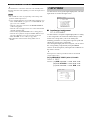
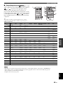
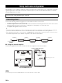
■ HDMI compatibility with this unit
• When CPPM copy-protected DVD audio is played back, video
and audio signals may not be output depending on the type of
the DVD player.
• This unit is not compatible with HDCP-incompatible HDMI or
DVI components.
• You can check the potential problem about the HDMI
connection (see page 41).
■ HDMI jack and cable plug
y
• We recommend that you use an HDMI cable shorter than 5
meters (16 feet) with the HDMI logo printed on it.
• Use a conversion cable (HDMI jack
↔ DVI-D jack) to connect
this unit to other DVI components.
• Do not disconnect or connect the cable or turn off the power of
the HDMI components connected to the HDMI OUT jack of
this unit while data is being transferred. Doing so may disrupt
playback or cause noise.
• Audio signals input at input jacks other than the HDMI IN 1 or
HDMI IN 2 jack of this unit cannot be digitally output at the
HDMI OUT jack.
• If you turn off the power of the video monitor connected to the
HDMI OUT jack via a DVI connection, this unit may fail to
establish the connection to the component.
• The analog video signals input at the composite video, S-video
and component video jacks can be digitally up-converted to be
output at the HDMI OUT jack. Set “VIDEO CONV.” to “ON”
in “MANUAL SETUP” (see page 79) to activate this feature.
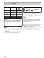
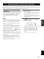
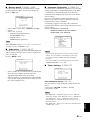
Information on HDMI™
Audio signal
types
Audio signal
formats
Compatible
HDMI
components
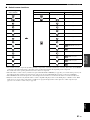
2ch Linear PCM 2ch, 32-192 kHz,
16/20/24 bit
CD, DVD-Video,
DVD-Audio, etc.
Multi-ch Linear
PCM
8ch, 32-192 kHz,
16/20/24 bit
DVD-Audio, etc.
DSD 2/5.1ch,
2.8224 MHz, 1 bit
SACD, etc.
Bitstream Dolby Digital, DTS DVD-Video, etc.
This unit’s HDMI interface is based on the following
standards:
• HDMI Version 1.2a (High-Definition Multimedia
Interface Specification Version 1.2a) licensed by
HDMI Licensing, LLC.
• HDCP Revision 1.1 (High-bandwidth Digital
Content Protection System Revision 1.1) licensed
by Digital Content Protection, LLC.
Notes
Notes
HDMI
HDMI cable plug

17 En
Connections
PREPARATION
English
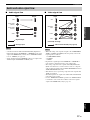
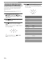
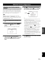
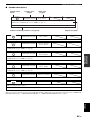
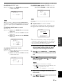
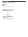
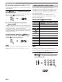
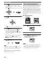
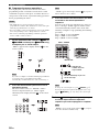
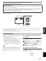
■ Audio signal flow
• 2-channel as well as multi-channel PCM, Dolby Digital and
DTS signals input at the HDMI IN 1 or HDMI IN 2 jack can be
output at the HDMI OUT jack only when “SUPPORT AUDIO”
is set to “OTHER” (see page 75).
• Audio signals input at the HDMI IN jacks are not output at the
AUDIO output and DIGITAL OUTPUT jacks.
■ Video signal flow
• When the analog video signals are input at the COMPONENT
VIDEO, S VIDEO and VIDEO jacks, the priority order of the
input signals is as follows:
1. COMPONENT VIDEO
2. S VIDEO
3. VIDEO
• Digital video signals input at the HDMI IN 1 or HDMI IN 2
jack cannot be output from analog video output jacks.
• The analog component video signals with 480i (NTSC)/576i
(PAL) of resolution are converted to the S-video or composite
video signals and output at the S VIDEO MONITOR OUT and
VIDEO MONITOR OUT jacks.
• This unit does not accept analog component video signals with
1080p of resolution.
• The OSD signal is not output at the VCR OUT and DVR OUT
jacks and is not recorded.
• Use the “HDMI UP-SCALING” parameter in “DISPLAY SET”
to deinterlace and convert the resolution of the video signals
output at the HDMI OUT jack (see page 79).
Audio and video signal flow
Notes
DIGITAL AUDIO
(OPTICAL)
DIGITAL AUDIO
(COAXIAL)
HDMI
AUDIO
OutputInput
Analog output
Digital output
Notes
S VIDEO
VIDEO
COMPONENT
VIDEO
HDMI
Through
OutputInput
Video conversion ON (see page 79)

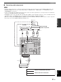
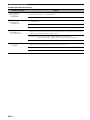
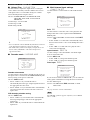
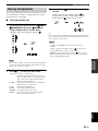
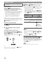
18 En
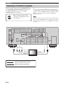
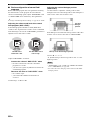
Connections
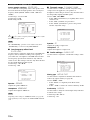
Connect your TV (or projector) to the HDMI OUT jack,
the COMPONENT VIDEO MONITOR OUT jacks, the
S VIDEO MONITOR OUT jack or the VIDEO
MONITOR OUT jack of this unit.
y
You can choose to play back HDMI audio signals on this unit or
on another HDMI component connected to the HDMI OUT jack
of this unit. Use the “SUPPORT AUDIO” parameter in “SOUND
MENU” to select the component to play back HDMI audio
signals (see page 75).
Some video monitors connected to this unit via a DVI connection
fail to recognize the HDMI audio/video signals being input if they
are in the standby mode. In this case, the HDMI indicator flashes
irregularly.
Connecting a TV monitor or projector
Make sure that this unit and other
components are unplugged from the
AC wall outlets.
Note
MONITOR
OUT
MONITOR OUT
S VIDEO
VIDEO
HDMI
OUT
COMPONENT VIDEO VIDEO
YP
B
P
R
PRPB
V
S
Y
TV (or projector)
Video in
Component
video in
S-video in
HDMI in
indicates recommended connections
indicates alternative connections
Seite wird geladen ...
Seite wird geladen ...
Seite wird geladen ...
Seite wird geladen ...
Seite wird geladen ...
Seite wird geladen ...
Seite wird geladen ...
Seite wird geladen ...
Seite wird geladen ...
Seite wird geladen ...
Seite wird geladen ...
Seite wird geladen ...
Seite wird geladen ...
Seite wird geladen ...
Seite wird geladen ...
Seite wird geladen ...
Seite wird geladen ...
Seite wird geladen ...
Seite wird geladen ...
Seite wird geladen ...
Seite wird geladen ...
Seite wird geladen ...
Seite wird geladen ...
Seite wird geladen ...
Seite wird geladen ...
Seite wird geladen ...
Seite wird geladen ...
Seite wird geladen ...
Seite wird geladen ...
Seite wird geladen ...
Seite wird geladen ...
Seite wird geladen ...
Seite wird geladen ...
Seite wird geladen ...
Seite wird geladen ...
Seite wird geladen ...
Seite wird geladen ...
Seite wird geladen ...
Seite wird geladen ...
Seite wird geladen ...
Seite wird geladen ...
Seite wird geladen ...
Seite wird geladen ...
Seite wird geladen ...
Seite wird geladen ...
Seite wird geladen ...
Seite wird geladen ...
Seite wird geladen ...
Seite wird geladen ...
Seite wird geladen ...
Seite wird geladen ...
Seite wird geladen ...
Seite wird geladen ...
Seite wird geladen ...
Seite wird geladen ...
Seite wird geladen ...
Seite wird geladen ...
Seite wird geladen ...
Seite wird geladen ...
Seite wird geladen ...
Seite wird geladen ...
Seite wird geladen ...
Seite wird geladen ...
Seite wird geladen ...
Seite wird geladen ...
Seite wird geladen ...
Seite wird geladen ...
Seite wird geladen ...
Seite wird geladen ...
Seite wird geladen ...
Seite wird geladen ...
Seite wird geladen ...
Seite wird geladen ...
Seite wird geladen ...
Seite wird geladen ...
Seite wird geladen ...
Seite wird geladen ...
Seite wird geladen ...
Seite wird geladen ...
Seite wird geladen ...
Seite wird geladen ...
Seite wird geladen ...
Seite wird geladen ...
Seite wird geladen ...
Seite wird geladen ...
Seite wird geladen ...
Seite wird geladen ...
Seite wird geladen ...
Seite wird geladen ...
Seite wird geladen ...
Seite wird geladen ...
Seite wird geladen ...
Seite wird geladen ...
Seite wird geladen ...
Seite wird geladen ...
Seite wird geladen ...
Seite wird geladen ...
Seite wird geladen ...
Seite wird geladen ...
Seite wird geladen ...
Seite wird geladen ...
Seite wird geladen ...
Seite wird geladen ...
Seite wird geladen ...
Seite wird geladen ...
Seite wird geladen ...
Seite wird geladen ...
Seite wird geladen ...
Seite wird geladen ...
Seite wird geladen ...
Seite wird geladen ...
Seite wird geladen ...
Seite wird geladen ...
Seite wird geladen ...
Seite wird geladen ...
-
 1
1
-
 2
2
-
 3
3
-
 4
4
-
 5
5
-
 6
6
-
 7
7
-
 8
8
-
 9
9
-
 10
10
-
 11
11
-
 12
12
-
 13
13
-
 14
14
-
 15
15
-
 16
16
-
 17
17
-
 18
18
-
 19
19
-
 20
20
-
 21
21
-
 22
22
-
 23
23
-
 24
24
-
 25
25
-
 26
26
-
 27
27
-
 28
28
-
 29
29
-
 30
30
-
 31
31
-
 32
32
-
 33
33
-
 34
34
-
 35
35
-
 36
36
-
 37
37
-
 38
38
-
 39
39
-
 40
40
-
 41
41
-
 42
42
-
 43
43
-
 44
44
-
 45
45
-
 46
46
-
 47
47
-
 48
48
-
 49
49
-
 50
50
-
 51
51
-
 52
52
-
 53
53
-
 54
54
-
 55
55
-
 56
56
-
 57
57
-
 58
58
-
 59
59
-
 60
60
-
 61
61
-
 62
62
-
 63
63
-
 64
64
-
 65
65
-
 66
66
-
 67
67
-
 68
68
-
 69
69
-
 70
70
-
 71
71
-
 72
72
-
 73
73
-
 74
74
-
 75
75
-
 76
76
-
 77
77
-
 78
78
-
 79
79
-
 80
80
-
 81
81
-
 82
82
-
 83
83
-
 84
84
-
 85
85
-
 86
86
-
 87
87
-
 88
88
-
 89
89
-
 90
90
-
 91
91
-
 92
92
-
 93
93
-
 94
94
-
 95
95
-
 96
96
-
 97
97
-
 98
98
-
 99
99
-
 100
100
-
 101
101
-
 102
102
-
 103
103
-
 104
104
-
 105
105
-
 106
106
-
 107
107
-
 108
108
-
 109
109
-
 110
110
-
 111
111
-
 112
112
-
 113
113
-
 114
114
-
 115
115
-
 116
116
-
 117
117
-
 118
118
-
 119
119
-
 120
120
-
 121
121
-
 122
122
-
 123
123
-
 124
124
-
 125
125
-
 126
126
-
 127
127
-
 128
128
-
 129
129
-
 130
130
-
 131
131
-
 132
132
-
 133
133
-
 134
134
-
 135
135


Yamaha RX-V861 Bedienungsanleitung
- Kategorie
- AV-Receiver
- Typ
- Bedienungsanleitung
in anderen Sprachen
- English: Yamaha RX-V861 Owner's manual
- français: Yamaha RX-V861 Le manuel du propriétaire
- dansk: Yamaha RX-V861 Brugervejledning
- svenska: Yamaha RX-V861 Bruksanvisning
- română: Yamaha RX-V861 Manualul proprietarului
Verwandte Artikel
-
Yamaha RX-V661 Bedienungsanleitung
-
Yamaha RX-V365 Bedienungsanleitung
-
Yamaha RX-V1500 Bedienungsanleitung
-
Yamaha V2500 - AV Receiver Bedienungsanleitung
-
-
-
-
-
-